Note : Les descriptions sont présentées dans la langue officielle dans laquelle elles ont été soumises.
CA 02858618 2014-08-06
BREATHABLE GARMENT
FIELD OF THE INVENTION
[0001] The invention relates to windproof and waterproof clothing when
used by persons
who are engaged in active pursuits, such as those involving either work or
recreation.
Specifically this invention relates to a method for protecting persons from
the negative effects of
wind or rain, while simultaneously providing means for the hot, moist air
generated by their
body to vent to the exterior of their clothes so that the vapor doesn't
condense inside their clothes
and make them wet. This problem has been recognized and ventilation systems
have been
created for clothing that can be opened by various means such as zippers,
however in the event
of rain these vents must be closed to prevent water from entering into the
clothing from the
outside and then the moist air created by the body condenses on the interior
of the clothing.
BACKGROUND OF THE INVENTION
[0002] Waterproof clothing has until the present time been constructed
either from
coated fabric such that it is absolutely windproof and waterproof, or from
fabric with a
membrane that keeps water (such as rain) from penetrating the fabric from the
exterior but which
is, to some degree, permeable to vapor such as that created by the human body
under exertion.
- 1 -
CA 02858618 2014-08-06
However, neither material allows substantial amounts of heat or moisture to
move from the
interior to the exterior of clothing constructed from the material. The result
is that heat and
moisture will accumulate within a very short time when the user is active.
This in turn results in
overheating, a drop in performance, and the wearer becoming wet from moisture
condensing
inside the clothing. Conversely in a colder environment, the wearer sweats
during active times
then the dampness remaining on the wearer's body over chills the body during
rest periods. The
term clothing as used in the description of the present invention relates to
jackets, trousers, shirts,
and headgear.
[0003] Other methods have been developed to allow for the venting of wind
and
waterproof clothing while preventing the intrusion of rain. US Pat. No.
7,043,767 to Jaeger
discloses a ventilation system for clothing utilizing a shingled construction.
However, this
system is expensive to construct and is very limited in the range of materials
that can be used.
[0004] Similarly, Japanese Patent No. 2008038323 Fukuyama Teruyoshi
discloses a
similar shingled construction to create ventilation, but suffers from the same
drawbacks as
Jaeger.
[0005] Another method of allowing for ventilation while preventing rain
from
penetrating is US Patent Application Publication No. 2010/242149 to Mickle et
al., which
discloses a series of vents using spacer materials as baffles to allow air
flow while keeping rain
water out. This approach, however, is expensive to construct, can only use a
limited range of
materials and is bulky.
- 2 -
CA 02858618 2014-08-06
[0006] The prior-art techniques attempt to prevent the intrusion of water
while allowing
for the venting of vapor. But the prior methods have a number of
disadvantages: a) the
construction costs of creating the vents using elaborate combinations of
materials are prohibitive;
b) the shingled construction with multiple layers of materials creates added
bulk that feels
awkward and constrains movement; c) the amount of air flow through the vents
is limited by the
various meshes it has to pass through; and d) the designs limit the range of
materials that can
used to create the clothing.
SUMMARY OF THE INVENTION
[0007] The present disclosure relates to windproof and waterproof
clothing for use by
persons who are engaged in active pursuits involving either work or recreation
as well as other
applications in which both waterproofing and breathability are important. In
particular, the
present disclosure is related to an apparatus including at least one panel
defining one or more
apertures and including a flexible material. One or more vent assemblies are
secured to the at
least one panel for each aperture of the one or more apertures. Each vent
assembly includes a
base portion secured to the at least one panel and defining an opening
overlapping the each
aperture. An outer ridge is secured to the base portion and an inner ridge
secured to the base
portion, the inner ridge being encircled by the outer ridge. A cap is secured
to the base portion
and has an outer perimeter positioned between the inner ridge and the outer
ridge, the cap, inner
ridge, and outer ridge defining a channel in fluid communication with the
opening. The base
may include a flange for bonding to the panel.
- 3 -
CA 02858618 2014-08-06
[0008] In some embodiments, the outer ridge defines one or more notches,
which may be
non-uniformly distributed around the outer ridge. The outer ridge may extend
outwardly from
the base more than the inner ridge. The perimeter of the cap may be offset
from the base a
distance less than the extent of the outer ridge outwardly from the base.
[0009] In some embodiments, the base defines a plurality of receptacles
and the cap has a
plurality of posts secured thereto and sized to insert within the receptacles.
The end portions of
the plurality of posts may include a widened portion configured to resist
removal of the end
portions from the receptacles.
BRIEF DESCRIPTION OF THE DRAWINGS
[0010] Preferred and alternative embodiments of the present invention are
described in
detail below with reference to the following drawings. These depict particular
embodiments of
the invention and are not intended to limit the scope of the invention set
forth in the claims.
[0011] FIG. 1 shows a front view of the liner portion with molded
synthetic fittings in the
front panels of the jacket.
[0012] FIG. 2 is a view of the molded vent openings as seen from below
showing how
they create an arch, which allows air to flow from the interior to the
exterior of the liner.
[0013] FIG. 3 is a section view of the molded vent opening showing how it
protects the
opening from water intrusion while still allowing air to flow from the
interior to the exterior of
the liner.
[0014] FIG. 4 shows a side view of the liner portion with vents in the
front and rear of
the jacket, as well as on the sleeve.
- 4 -
CA 02858618 2014-08-06
[0015] FIG. 5 is a view of the vents created by a piece of fabric with a
stiffened edge
tacked down in a manner that creates a series of arches to allow airflow.
[0016] FIG. 6 is a section view of the overlapping fabric panels with the
upper panel
having a stiffened edge, and the lower panel having a raised dam portion on
the interior of the
opening.
[0017] FIG. 7 is a section view of the overlapping fabric panels on the
sleeve with the
upper panel having a stiffened edge, and the lower panel having a raised dam
portion on interior
of the opening, with an additional dam portion on the exterior of the opening.
[0018] FIG. 8 is a cut away view of the front panels of the shell portion
of the jacket
showing the liner portion with the molded synthetic fittings.
[0019] FIG. 9 shows a front view of the liner portion of the trousers
with the molded
synthetic fittings in the front panels.
[0020] FIG. 10 is a cut away view of the front panels of the shell
portion of the trousers
showing the liner portion with the molded synthetic fittings.
[0021] FIGS. 11A and 11B are upper and lower isometric views of a vent
assembly in
accordance with an embodiment of the present invention.
100221 FIGS. 12A and 12B are upper and lower isometric views of a base
portion of a
vent assembly in accordance with an embodiment of the present invention.
[0023] FIGS. 13A and 13B are upper and lower isometric views of an upper
portion of a
vent assembly in accordance with an embodiment of the present invention.
- 5 -
CA 02858618 2014-08-06
[0024] FIG. 14 is a side cross-sectional view of a vent assembly in
accordance with an
embodiment of the present invention.
[0025] FIG. 15 is a partial side cross-sectional view of a vent assembly
in accordance
with an embodiment of the present invention.
[0026] FIG. 16 is a front elevation view of a garment including vent
assemblies in
accordance with an embodiment of the present invention.
[0027] FIG. 17 is an isometric view of a tent including vent assemblies
in accordance
with an embodiment of the present invention.
DETAILED DESCRIPTION OF THE PREFERRED EMBODIMENTS
[0028] A preferred embodiment of the method of the present invention is
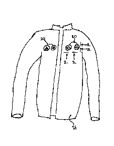
illustrated in
Fig.1 which shows the liner 21 of a jacket with vents 20 set into the fabric
of the anterior upper-
thorax region wherein the materials used in the construction may be inherently
flame resistant
such as Nomex, FR (Flame Resistant) Modacrylic, FR Urethane and FR Vinyl. Fig.
2 shows a
view from below of the opening of the vent 20, which will allow for the
movement of warm
moist air away from the body. Fig. 3 shows a section view of vent 20 showing
how the vent
includes a vent hood affixed to the material of the jacket liner such that it
surrounds a hole in the
liner such that air can escape but water is prevented from entering.
[0029] Fig. 4 shows another embodiment of the method for creating a
series of vents 22
in the liner portion of the current invention utilizing a series of shingle-
like, over-lapping panels
of fabric arranged so that water running down will fall from panel to panel
until reaching the
lower hem of the garment. For purposes of illustration, only a single row of
vents 22 are shown;
- 6 -
CA 02858618 2014-08-06
however, any number of rows of vents 22 can be included. In addition, the
vents 22 are not
necessarily in rows, but rather can be arranged individually in any suitable
pattern or in an
arbitrary pattern. The fabric panels are joined together at intervals allowing
gaps in the seams
that will allow airflow to carry hot, moist air away from the user's body. The
material of the
fabric panels itself may not be breathable; however, by virtue of the vents
the hot, moist air is
permitted to exit the garment and therefore achieve breathability.
[0030] Fig. 5 shows a view of the vent 22 from below showing how the vent
panel 22 is
fastened. A sewn construction is utilized that is later sealed against water
intrusion.
Alternatively the vent panel 22 is fastened with Radio Frequency welding
methods 26 at
intervals to the liner 21. Preferably,. a dam portion 23 is also employed,
which prevents water
from moving up and through the vent.
[0031] Fig. 6 shows a cross sectional view of the construction details of
the vent 22 with
the core stiffening element 25 and the placement and construction of the dam
23 with its core
element 24. Fig. 7 shows the same cross section view as Fig. 6 with the
addition of a second dam
portion 23 placed outside of the vent 22 to provide additional protection from
water moving into
and through the vent opening.
[0032] Fig. 8 shows a cut-away view of the shell portion 27 of the jacket
revealing the
vents 20 in the liner portion 21 of the jacket. Fig. 9 shows the liner 28 of a
pair of trousers with
vents 20 set into the fabric of the anterior upper-thigh region. Fig. 10 shows
a cut-away view of
- 7 -
CA 02858618 2014-08-06
the shell portion 29 of the pair of trousers revealing the vents 20 in the
liner portion 21 of the
trousers.
[0033] Figs. 11A and 11B illustrate a vent assembly 30 that may be used
to provide
breathability for a garment or in other applications. The vent assembly 30 may
include an upper
portion 34 and a lower portion 32. The lower portion 32 may define a base
plate 36 having a
generally planar shape. The vent assembly 30 may secure to a garment or some
other device by
means of the base plate 36.
[0034] Fig. 12A and Fig. 12B illustrate the base portion 32 of the vent
assembly 30. The
base portion 32 may define an outer ridge 38 and an inner ridge 40. The outer
ridge 38 encircles
the inner ridge 40. The ridges 38, 40 may be separated from one another by a
gutter portion 42.
The ridges 38, 40 extend outwardly from the base plate 16 in the same
direction and to a greater
extent than the gutter portion 42. The gutter portion 42 may be defined as a
portion of the base
plate 36 positioned between the ridges 38, 40. In the illustrated embodiment,
the ridges 38, 40
and base plate 36 all have a circular perimeter shape. However, other
perimeter shapes may also
be used. In the illustrated embodiment, the outer ridge 38 defines one or more
grooves 44 to
facilitate drainage of fluids that may collect in the gutter portion 42. The
grooves 44 may be
distributed non-uniformly around the outer ridge 38. For example, the grooves
44 may only be
present in one half of the outer ridge 38. In this manner the un-grooved
portion of the outer
ridge 38 may be positioned vertically above the grooved portion thereby
allowing water to drain
from the gutter portion 42 but hindering falling water from entering the
gutter portion 42.
- 8 -
CA 02858618 2014-08-06
[0035] As will be described in greater detail below, the upper portion 34
may mount to
the lower portion by means of receivers 46 secured to the base plate 36. The
receivers 46, outer
ridge 38, and inner ridge 40 may be disposed about an aperture 48 defined by
the base plate 36.
The aperture 48 is preferably large, e.g. have a diameter larger than 50%,
preferably larger than
75%, of the diamter of the outer ridge 38. In the illustrated embodiment, the
outer ridge 38 and
inner ridge 40 are concentric with each other and the aperture 48 and the
receivers 46 protrude
into the aperture 48. However, other configurations may also be used,
including eccentric
configurations.
[0036] Fig. 13A and Fig. 13B illustrate the upper portion 34 of the vent
assembly 30.
The upper portion 34 may define an outer cover 50 that provides a continuous
waterpoof area
within a perimeter 52. The cover 50 may have posts 54 or some other fastening
structure
extending from a lower surface thereof to enable securement of the cover 50 to
the base
portion 32. The posts 54 may protrude from the outer cover 50 or from
pedestals 56 or some
other structure secured to a lower surface of the cover 50.
[0037] Referring to Fig. 14, in the illustrated embodiment, the posts 54
may be inserted
into the receivers 46 in order to fasten the upper portion 34 to the lower
portion 32. The posts 54
may be secured within the receivers 56 by means of adhesives, an interference
fit, or some other
means. In the illustrated embodiment, the posts 54 have a widened distal
portion 58. During
insertion one or both of the distal portion 58 and the receiver 46 may
elastically deform. When
the distal portion 58 emerges from the receiver 46, one or both of the distal
portion 58 and
- 9 -
CA 02858618 2014-08-06
receiver 46 may elastically return to approximately their original dimensions
such that the
widened distal portion 58 will resist removal of the posts 54 from wtihin the
receivers 46. In the
illustrated embodiment, the receivers 46 have a tapered, e.g. conical, shape
to facilitate insertion
of the widened portion. The receivers 46 may be formed in a member 60 that
protrudes into the
aperture 48. When the posts 54 are inserted within the receivers 46, the
pedestals 56 may abut
the members 60.
100381 The base plate 36 may define a flange 62 extending radially
outward therefrom
enabling securement of the vent assembly 30 to a sheet 64 of material defining
an aperture for
receiving the vent assembly 30. In the illustrated configuraiton, the flange
62 secures to an inner
surface of the sheet 64 and the ridges 38, 40 and cover 50 extend through the
sheet 64 and extend
outwardly from an outer surface of the sheet 64. However, other configurations
are possible.
For example, the lower surface of the flange 62, and additionally or
alternatively other areas of
the base plate 36, could secure to the outer surface of the sheet 64. In such
embodiments, the
sheet 64 may define an aperture that overlaps with the aperture 48 when the
vent assembly is
installed.
[0039] In any of these configurations, the base plate 36 may secure to
the sheet 64 by
means of adhesives, stitching, welds (e.g. high frequency or radio frequency
welds), or some
other bonding technique. The lower portion 32 and upper portion 34 may be
formed of a rigid
material or a flexible material. For example, where the vent assembly 30 is
incorporated into a
garment a flexible vent assembly 30 may facilitate movement of the wearer and
reduce the
- 10-
CA 02858618 2014-08-06
likelihood of the vent assembly 30 tearing out of the garment. However, vent
assemblies 30
including a rigid or semirigid material may also be suitable for many
applications. Even with a
rigid material, the vent assembly 30 can function well with a flexible
material in a garment, for
example. The vents may be small enough that when strategically placed they do
not interfere
with movement and comfort. The vent assembly 30 may be constructed of vinyl,
coated
urethane, polyvinyl chloride (PVC), or other polymer materials.
[0040] The sheet 64 may be a breathable or non-breathable material. The
vent
assembly 30 is particularly useful with materials that are waterproof but not
breathable inasmuch
as these materials are less expensive than breathable materials. The sheet 64
may be a flexible
material, however rigid and semirigid materials may also be used as the sheet
64.
100411 Referring to Fig. 15, the inner ridge 40 has a height 66, the
outer ridge 38 has a
height 68, and the perimeter portion 52 of the cover 50 has an offset distance
70 relative to a
deepest point of the gutter portion 42. As shown, the height 68 may be greater
than the offset
distance 70 such that the outer ridge 68 is able to hinder ingress of water
under the cover 50.
The height 66 of the inner ridge 40 may be such that there is a gap between
the lower surface of
the cover 50 and the inner ridge 40. There may likewise be a circumferential
gap between the
perimeter 52 of the cover 30 and the outer ridge 38. In this manner, air flow
72 is permitted
through the aperture 48, between the inner ridge 40 and the cover 50, and
through the gap
between the outer ridge 38 and the perimeter 52.
- 11 -
CA 02858618 2014-08-06
[0042] Referring to Fig. 16, a garment 74, such as a jacket, windbreaker,
pants, or the
like may incorporate vent assemblies 30 as described hereinabove in one or
more panels of
material forming the garment 74. For example, a garment may include upper
vents 76 and lower
vents 78 such that the upper vents 76 are higher than the lower vents 78 when
the garment 74 is
worn by a person standing upright. In this manner, convection will tend to
draw air through the
lower vents 78 and expell air through the higher vents 76. Vents may be placed
at other strategic
areas, such as vents 80 placed in the armpit area of the garment 74. As noted
herein, each
vent 76, 78, 80 may be placed in or over an aperture defined by the panel in
which it is placed.
[0043] Referring to Fig. 17, in other applications, vent assemblies 30
may be
incorporated into a tent 82, such as a single-walled tent. In single-walled
tents, a single layer of
material must provide both a waterproof covering and permit venting for
breathing and to reduce
condensation on the inner surface of the tent. Accordingly, a panel of the
tent 82 may have
vents 84, 86 mounted thereto, such as vents 84, 86 embodied as a vent assembly
30 described
herein. As for the embodiment of Fig. 16, the tent 82 may include upper vents
84 and lower
vents 86 positioned such that the upper vents 84 are vertically above the
lower vents 86 when the
tent is set up, thereby promoting venting due to convection.
[0044] While the preferred embodiments of the invention have been
illustrated and
described, as noted above, many changes can be made without departing from the
scope of the
invention. Accordingly, the scope of the invention is not limited by the
disclosure of the
- 12 -
CA 02858618 2014-08-06
preferred embodiment. Instead, the invention should be determined entirely by
reference to the
claims that follow.
- 13 -