Note : Les descriptions sont présentées dans la langue officielle dans laquelle elles ont été soumises.
CA 02859280 2014-06-13
WO 2013/090721
PCT/US2012/069751
MINIMALLY INVASIVE METHOD AND APPARATUS
FOR STABILIZING THE SPINAL COLUMN
RELATED INVENTIONS
This application claims benefit of priority of U.S. Provisional Application
Nos.
61/570,535, filed December 14, 2011, entitled "Minimally Invasive System and
Method for
Stabilizing the Spinal Column;" 61/588,823, filed January 20, 2012, entitled
"Disposable Kit for
Minimally Invasive Spine Surgery;" 61/614,596, filed March 23, 2012, entitled
"Construct for
Stabilization of Spinal Column;" 61/614,863, filed March 23, 2012, entitled
"Automatic
Instrument and Kit for Spinal Surgery;" and 61/735,327, filed December 10,
2012, entitled
"Implants for Stabilizing the Spinal Column." All of the above-identified
related applications
are incorporated herein by reference.
FIELD OF THE INVENTION
The present invention relates generally to corrective spinal procedures and
implants; and
more particularly to a minimally invasive method, implant, and instrument
system for stabilizing
the spinal column.
BACKGROUND OF THE INVENTION
Spinal fusion is a surgical technique where one or more vertebrae are united
to reduce
movement between the vertebrae. Fusion is utilized to treat a number of spinal
conditions,
including spinal deformities, spinal stenosis, and spondylolisthesis. In order
to maximize the
likelihood of a successful fusion, instrumentation is often used as an
internal splint to stabilize
the vertebral column and aid in bone healing. These instrumentation systems
typically utilize a
screw which is inserted into the pedicle to act as an anchor. These anchors
are then paired with
rods to stabilize each side of the vertebral column. Many pedicle screw
systems are complex,
utilizing a number of instruments to anchor the screws and fix the rods in
place. The
instrumentation system and method described herein minimizes this complexity,
reducing
operating time for the end user.
Previous embodiments of this type of implant have utilized a tulip head design
affixed
onto a screw. In these embodiments, a stabilizing rod is inserted into the
tulip head and locked
1
CA 02859280 2014-06-13
WO 2013/090721
PCT/US2012/069751
into place with a locking cap. These tulip head and screw embodiments
typically incorporate
polyaxial movement, affording a surgeon flexibility to bend the rod to fit a
specific patient's
spinal anatomy.
SUMMARY OF THE INVENTION
The present invention provides a unique and novel method, implant, and
instruments for
stabilizing the spinal column. In one aspect, an implant of the present
invention includes a
pedicle screw, a retainer, and an elongated member. In this aspect, the
methods, implants, and
instrumentation of the present invention can be designed to allow a user to
insert the implant in
one piece.
In one embodiment of the invention, an implant for stabilizing a spinal column
includes a
pedicle screw with pedicle head at a proximal end thereof An elongated member
is fixedly
connected to and extends proximally from the pedicle head, away from the
pedicle screw. The
elongated member has external threads over at least a portion of a
longitudinal periphery thereof
Also included is a retainer having an unthreaded internal passage providing
that the retainer is
freely slidable over the elongated member. The retainer has an opening
therethrough to receive a
rod used to fix one implant to another. Lastly, a lock nut having a threaded
internal passage
engages the external threads of the elongated member. Threadable longitudinal
translation of the
lock nut distally along the elongated member, and against the retainer,
secures and retains a rod
between the retainer and the pedicle head, thereby providing a fixing of one
implant to another.
The opening through the retainer can be configured to form a slot to receive a
rod used to
fix one implant to another. The slot can be longitudinally aligned within the
retainer generally
perpendicularly to a longitudinal axis of the implant, the slot being on one
side of, and
immediately adjacent to, the elongated member. In another embodiment, the
retainer can include
two, diametrically opposed openings therethrough, the two openings forming two
diametrically
opposed slots, each slot configured to receive one rod used to fix one implant
to another. The
two slots provide that two rod portions be secured and retained between the
retainer and the
pedicle head. In this another embodiment, each slot can also be longitudinally
aligned generally
perpendicularly to a longitudinal axis of the implant, each slot being on a
diametrically opposed
side of, and immediately adjacent to, the elongated member.
2
CA 02859280 2014-06-13
WO 2013/090721
PCT/US2012/069751
In a further embodiment, the elongated member includes a break-away reveal
providing
for shearing off of a longitudinal portion of the elongated member at a
specified torsional force.
The break-away reveal can be a notch in, a hole in, or a hole through the
elongated member. The
break-away reveal can be located on the elongated member to align the break-
away reveal
generally with a proximal end of the lock nut after the lock nut is translated
toward the retainer to
secure and retain a rod between the retainer and the pedicle head.
In an alternative embodiment, the elongated member can include reverse screw
threading
within a recess in a proximal end of the pedicle screw, or in a distal end of
the elongated
member. The distal end of the elongated member, or proximal end of pedicle
screw, includes
threads engageable with the respective recess. The reverse screw threading
thereby allows a lock
nut driver tool to provide counter torque to the implant to tighten the lock
nut against a head of
the pedicle screw without driving the pedicle screw further into a vertebra.
In another embodiment, the lock nut includes a recess to receive a distal tip
of a lock pin
during implant insertion. The lock pin can be longitudinally positioned within
a drive tool, and
alongside the elongated member, to prevent the lock nut from turning on, and
relative to, the
elongated member. This prevents the lock nut from prematurely tightening
against the retainer,
when the drive tool engages the implant to translate torque to the implant to
drive the pedicle
screw into a vertebra.
Further embodiments of the present invention provide for polyaxial movement
between
the elongated member and the pedicle screw. This can be achieved by a swivel
ball being
provided at a distal end of the elongated member or at the proximal end of the
pedicle screw,
with respective counter socket joint. The swivel ball and joint allows the
elongated member to
articulate within a head of the pedicle screw. Further embodiments may also
include two piece
retainers (upper and lower retainer portions). The upper and the lower
retainer portions can fix
and secure therebetween one or two rods. A two rod embodiment could instead be
a one-piece,
U-shaped rod. The U-shaped rod allows for better biomechanical balancing of
the entire
construct.
Accordingly, in one embodiment, an implant for stabilizing a spinal column
includes a
pedicle screw, and elongated member, and a retainer having an upper and a
lower retainer
portion. The elongated member is polyaxially movably connected to the pedicle
screw, and has
3
CA 02859280 2014-06-13
WO 2013/090721
PCT/US2012/069751
external threads over at least a portion of a longitudinal periphery thereof
The upper retainer
portion and the lower retainer portion each have a concave opening
therethrough to receive a rod
used to fix one implant to another. The upper retainer portion can be
internally threaded to
engage the external threads of the elongated member to threadably translate
longitudinally along
the elongated member by rotation of the elongated member about a longitudinal
axis thereof
The upper retainer portion thereby translates toward the lower retainer
portion to secure and
retain a rod between the upper retainer portion and the lower retainer portion
to provide a fixing
of one implant to another.
In another embodiment, the elongated member includes a break-away reveal
providing
for shearing off of a longitudinal portion of the elongated member at a
specified torsional force.
The break-away reveal can again be a notch in, a hole in, or a hole through
the elongated
member. The break-away reveal can also be located on the elongated member to
align the break-
away reveal generally with a proximal end of the upper retainer portion after
the upper retainer
portion is translated toward the lower retainer portion to secure and retain a
rod therebetween.
In a further embodiment, the elongated member includes a swivel ball fixedly
connected
at a distal end thereof. The swivel ball resides within a concave recess of a
head of the pedicle
screw, thereby providing a polyaxially movable connection between the
elongated member and
the pedicle screw. The swivel ball can be movably secured within the concave
recess of the head
of the pedicle screw by a swivel connector head threadably connected, welded
and/or press fit to
the head of the pedicle screw. This provides the polyaxially movable
connection between the
elongated member and the pedicle screw. If threaded, internal threads of the
swivel connector
head can engage external threads of the head of the pedicle screw.
In still another embodiment, the concave openings through the upper and the
lower
retainer portions can form a slot to receive a rod used to fix one implant to
another. The slot can
be longitudinally aligned generally perpendicularly to a longitudinal axis of
the implant, and the
slot can be on one side of, and immediately adjacent to, the elongated member.
Alternatively,
the upper and the lower retainer portions each have two, diametrically opposed
concave openings
therethrough, forming two diametrically opposed slots, each slot being
configured to receive a
rod used to fix one implant to another. The two slots provide that two rod
portions can be
secured and retained between the upper and the lower retainer portions. If two
slots, for two rods
4
CA 02859280 2014-06-13
WO 2013/090721
PCT/US2012/069751
(or two rod portions), are provided, each slot can be longitudinally aligned
generally
perpendicularly to a longitudinal axis of the implant, each slot being on a
diametrically opposed
side of, and immediately adjacent to, the elongated member.
If two slots are together provided within the upper and the lower portions,
for two rods
(or two rod portions), the two rod portions (at the implant) could rather be
one, U-shaped rod.
The one, U-shaped rod can extend along a plurality of implants, with each
implant securing and
retaining two adjacent rod portions of the U-shaped rod. The one, U-shaped rod
can have a U-
shaped bend located at a respective end of the plurality of implants.
In a still further embodiment, the implant also includes a retaining pin. The
retaining pin
can be threadably engageable with the lower retainer portion, extending
proximally, and
longitudinally parallel to the elongated member. The retaining pin can pass
through a through
hole in the upper retainer portion.
In another embodiment, the lower retainer portion might include an unthreaded
internal
passage providing that the lower retainer portion is freely slidable over the
elongated member.
An underside of the lower retainer portion can be concave to provide for
mating and tightening
against an engagingly shaped head of the pedicle screw, under reduction, upon
translation of the
upper retainer portion toward the lower retainer portion to secure and retain
a rod therebetween.
BRIEF DESCRIPTION OF THE ILLUSTRATED EMBODIMENTS
The present invention will be better understood with reference to the
following
description taken in combination with the drawings. For the purpose of
illustration, there are
shown in the drawings certain embodiments of the present invention. In the
drawings, like
numerals indicate like elements throughout. It should be understood, however,
that the invention
is not limited to the precise arrangements, dimensions, and instruments shown:
FIGs. 1A-1D illustrate in cross-section an implant and system for stabilizing
a spinal
column, in accordance with one embodiment of the present invention;
FIGs. 2A-2C illustrate (FIG. 2A in exploded view) instruments for use while
performing
methods of stabilizing a spinal column, in accordance with aspects of the
present invention;
5
CA 02859280 2014-06-13
WO 2013/090721
PCT/US2012/069751
FIG. 3 illustrates in cross-section an implant for stabilizing a spinal
column, in
accordance with another embodiment of the present invention;
FIG. 4 illustrates in perspective view a system for stabilizing a spinal
column, in
accordance with another embodiment of the present invention, the system
including two implants
of the present invention with stabilization rod being inserted therebetween;
FIG. 5 illustrates in alternative perspective view the system for stabilizing
a spinal
column shown in FIG. 4, the system including two implants of the present
invention after
insertion with stabilization rod secured therebetween;
FIG. 6 illustrates in cross-section a portion of the implant for stabilizing a
spinal column
shown in FIG. 4;
FIG. 7A-7D illustrate in cross-section an implant and system for stabilizing a
spinal
column, in accordance with still another embodiment of the present invention;
FIGs. 8A-8B illustrate a perspective view, and a side cross-section view,
respectively, of
a kit for housing disposable medical instruments and implants, in accordance
with the present
invention; and
FIG. 9 illustrates an automatic instrument, and components thereof, used to
drive and
tighten implants and pedicle screws used in spinal surgery, in accordance with
the present
invention.
DETAILED DESCRIPTION OF THE INVENTION
Referring to FIGs. 1A-1D, an implant 1 for stabilizing a spinal column is
shown. The
implant 1 includes a pedicle screw 10 (a lower threaded shaft portion), a
receiver/retainer 50, a
threaded elongated member 40, and a lock nut 60. The elongated member 40 of
the implant 1
can be seen variously to: allow the complete construct (the threaded shaft of
the pedicle screw
10, the retainer 50, the elongated member 40, and the lock nut 60) to drive
down into the pedicle
as one unit; and to allow the elongated member 40 to apply a force to tighten
the lock nut 60 to
retain a rod 90 between the pedicle screw 10 and the retainer 50.
Regarding the implant 1, the lower threaded shaft portion (the pedicle screw)
10 is
adapted for screwing into a vertebra. The elongated member 40 projects from a
proximal end of
6
CA 02859280 2014-06-13
WO 2013/090721
PCT/US2012/069751
the pedicle screw 10, in a direction opposite the pedicle screw 10, and
includes an external
thread. The external thread of the elongated member 40 provides threadable
engagement with
the lock nut 6, allowing the lock nut 6 to be tightened into place to secure
the retainer 50 to a
proximal head of the pedicle screw 10. Securing the retainer 50 against the
proximal head of the
pedicle screw 10 retains the rod 90 therebetween.
In this embodiment, the retainer 50 can be one-piece, having an unthreaded
internal
passage providing that the retainer be freely slidable over the elongated
member. At least a
portion of a distal end of the retainer 50 could be rounded, curved or
concave, providing for
mating and tightening against an engagingly shaped proximal end of a head of
the pedicle screw,
under reduction, upon translation of the retainer 50, by the locknut 60,
toward the head of the
pedicle screw, to secure and retain a rod 90 therebetween. The retainer 50 can
have a through
slot to receive a rod 90. At least a portion of the inside of the slot would
be curved or rounded to
mate with the rod 90 under reduction. The slot can be longitudinally aligned
generally
perpendicularly to a longitudinal axis of the implant, the slot being on one
side of, and
immediately adjacent to, the elongated member and the head of the pedicle.
The elongated member 40 can further include a break-away reveal 20 (Fig. 1B);
or
alternatively can include a reverse screw 30. The break-away reveal 20 or
reverse screw 30
provide for the removal of portion of the elongated member 40 after insertion
and spinal column
stabilization. In the embodiment where the elongated member includes a break-
away feature 20,
the elongated member 40 can include a threaded external portion having
standard threading that
matches the threading of the pedicle screw 10.
During insertion of the implant 1, a lock pin 70 can be used to prevent the
lock nut 60
from prematurely tightening against the retainer 50 and to transfer torque
from the drive tool 95
to the pedicle screw 10 of the implant 1. The lock pin 70 can be positioned
longitudinally,
within the drive tool 95, alongside the elongated member 40, with distal tip
thereof inserted into
a recess in the lock nut 60 (see FIG. 1B). The lock pin 70, so positioned,
prevents the lock nut
60 from turning on, and relative to, the elongated member 40 when the drive
tool 95 engages the
periphery of the lock nut 60, to translate torque to the implant 1, to drive
the pedicle screw 10
into a vertebra. After insertion of the pedicle screw 10 into a vertebra, the
break-away reveal 20
allows a portion of the elongated member 40 to shear away from the pedicle
screw 1, under
7
CA 02859280 2014-06-13
WO 2013/090721
PCT/US2012/069751
certain torque, leaving a low profile to the elongated member 40. The low
profile of the sheared
elongated member 40 can be a height approximating a proximal end of the lock
nut 60 after the
lock nut 60 is tightened to retain the rod 90 between the pedicle screw 10 and
the retainer 50 (see
FIG. 1B).
The break-away reveal 20 in the elongated member 40 can be a notch therein, or
can be a
hole, or a through hole. If a notch, various shapes are possible, but a V-
notch if preferable. If a
hole or through hole, various shapes in cross-section are possible, but an
oval shaped through
hole is the preferable configuration for the break-away reveal 20.
Alternatively, the elongated member 40 could include a reverse screw 30 (see
FIG. 1D)
rather than a break-away reveal 20. The reverse screw 30 can involve a recess
in a proximal end
of the pedicle screw 10, where the recess includes an internal reverse thread.
A distal end of the
elongated member 40 would include a mating external threaded portion for
engagement within
the recess of the pedicle screw 10. The internal reverse thread allows a lock
nut driver tool 11
(see FIG. 2A) to provide counter torque so that the lock nut 60 can be
tightened against a head of
the pedicle screw 10 without driving the pedicle screw 10 further into a
vertebra. Because
reverse threading is utilized to tighten the lock nut 60 against the head of
the pedicle screw 10,
this alternative embodiment does not necessarily need to use a lock pin 70.
However, a lock pin
70 may still be desired to transfer torque from the drive tool 91 to the
pedicle screw 10.
Referring now to FIGs. 2A-2C, the drive tool 91 includes a driver shaft 93 and
a torque
handle 94 with a quick release mechanism 97. The drive tool 91 (particularly
the torque handle
94) provides that the implant 1 can be tightened to a finite torque
specification. The quick
release mechanism 97 associated with the torque handle 94 allows the torque
handle 94 to be
released from the driver shaft 93. The driver shaft 93 on the drive tool 91
can consist of a
smooth outer member and a lower portion, where the lower portion has a recess
with reverse
internal thread to mate with the external thread of the elongated member 40.
Depending on
whether a lock pin 70 is used, the drive tool 91 may or may not require an
internal cavity
providing for insertion of the lock pin 70.
In another embodiment, the driver shaft 93 would be hollow, with a distal tip
having an
internal mechanical driver design (e.g., hex) to engage an external periphery
of the head of the
pedicle screw 10. An internal recess at a distal end of the quick release
mechanism 97 would
8
CA 02859280 2014-06-13
WO 2013/090721
PCT/US2012/069751
also have a mechanical driver design (e.g., hex, reverse threads) to engage a
proximal end of the
elongated member 40. The driver shaft 93 would slide over the elongated member
40, so that the
distal tip thereof engages the head of the pedicle screw, then the recess at
the distal end of the
quick release mechanism 97 would be attached (e.g., threadably engaged) to the
proximal end of
the elongated member 40. In this embodiment, the driver shaft 93 has a lever
arm, facilitating
driving (turning of) the head of the pedicle screw by the driver shaft 93, and
the torque handle
facilitates driving, or turning of, the elongated member 40 to a more finite
torque specification.
This embodiment of the driver shaft 93 is also advantageous when using the
FIGs. 3-7
embodiments of the implant of the present invention, where the elongated
member 140, 240 is
rotationally movable relative to the head 219 of the pedicle screw 110, 210.
After insertion of the pedicle screw 10 into a vertebra, and in order to
stabilize the spinal
column, a rod 90 is used to fix multiple pedicle screws 10 relative to one
another. The rod 90
can consist of solid stock with a threaded outer portion on one or both ends
(see FIGs 1B and
2A). A guide cable 80 is utilized to pull the rod 90 through the retainers 50
of each implant 1.
To attach the guide cable 80 to the rod 90, the rod 90 can include an inner
cavity with internal
threading that engages external threading on an outer portion of the guide
cable 80. The guide
cable 80 could alternatively attach to the rod 90 by knot or ball at end of
guide cable 80 being
drawn through a side hole of rod 90 and catching within an adjoining end hole
of rod 90. A
cable hook 96 (see FIG. 2C), which can be comprised of metal, is used to grab
the guide cable 80
after the guide cable 80 has been passed through each retainer 50, to pull the
guide cable 80 from
a previous retainer 50 to a next retainer 50 along the spinal column.
Referring to FIG. 2B, a hybrid reamer 95, which can include a protruding,
sharpened tip,
can be used at the beginning of the procedure. In other pedicle screw systems,
a needle pin with
a sharpened tip is first inserted into a vertebra to prepare each vertebra for
a reamer. A reamer
tool would then be inserted to enlarge the vertebral opening, to prepare the
opening for a pedicle
screw. In the present invention, a needle pin and reamer are combined to form
a hybrid reamer
95, used to prepare an untapped vertebra for the pedicle screw 10 in one more
convenient step.
Methods of the present invention are used in the fixation of the spinal column
for the
treatment of a number of spinal conditions. Initially, the hybrid reamer 95 is
inserted into a
vertebra to prepare the pedicle thereof for insertion of the pedicle screw 10
of the implant 1. An
9
CA 02859280 2014-06-13
WO 2013/090721
PCT/US2012/069751
implant 1 is inserted into pedicles on each side of a vertebra, and perhaps in
a number of
vertebrae, of the spinal column ¨ each a relative distance from another. In
one aspect, a drive
tool 91 utilizes the threaded portion of the elongated member 40 to apply a
force to drive each
implant 1 into a pedicle of a vertebra. The lock pin 70 may be used to
transfer a torque force
from the drive tool 91 to the implant 1, to thereby prevent an inadvertent
tightening of the lock
nut 60 against the retainer 50 of the implant 1. In another aspect, a hollow
driver shaft 93 of the
drive tool 91 slides over the elongated member 40, and an internal mechanical
design (e.g., hex),
at a distal tip of the driver shaft 93, engages the periphery of the head of
the pedicle screw (or of
the lock nut 60, if using the lock pin 70) to apply a force to each implant 1
into a pedicle of the
vertebra.
After inserting each pedicle screw 10 to a proper depth in each pedicle, a
guide cable 80,
rod 90, and cable hook 96 are used to thread the rod 90 through each retainer
50. The retainers
50 are not initially tightened down, so there exists a larger opening therein
to allow for a
threading of the guide cable 80 and rod 90 therethrough. After placing the
guide cable 80 and
the rod 90 through a first retainer 50, a cable hook 96 then grapples the
guide cable 80 to pull the
guide cable 80 and the rod 90 through subsequent retainers. After the rod 90
is properly placed
within respective retainers 50, the guide cable 80 is detached from an end of
the rod 90.
Next, if used, the lock pin 70 is disengaged from the drive tool 91. A next
step of the
method depends whether the elongated member 40 employs a break-away reveal 20,
or a reverse
screw 30. If the elongated member 40 has a break-away reveal 20, removing the
lock pin 70
then allows the drive tool 91 to tighten the lock nut 60 against the retainer,
to retain and secure
the retainer against the head of the pedicle screw 10, thereby securing and
retaining the rod 90
within the retainer 50 and against the head of the pedicle screw 10 of the
implant 1.
Accordingly, as the lock nut 60 is tightened, translating the lock nut 60
along the elongated
member 40, the lock nut 60 pins the rod 90 against the head of the pedicle
screw 10, within the
retainer 50, fixing the rod 90 in place. The drive tool 91 is removed, and an
instrument can then
be used to shear-off a portion of the elongated member 40 at the break-away
reveal 20.
If the elongated member 40 has a reverse screw 30, the lock pin 70 may or may
not be
used to transfer torque from the drive tool 91 to the pedicle screw 10 of the
implant 1. After
removing the lock pin 70, if used, a lock nut driver tool 92 is inserted into
a proximal recess of
CA 02859280 2014-06-13
WO 2013/090721
PCT/US2012/069751
the elongated member 40 (see FIG. 2A). A distal end of the elongated member 40
would include
a mating external threaded portion for engagement within the recess of the
pedicle screw 10.
The internal reverse thread allows a lock nut driver tool 11 to provide
counter torque so that the
lock nut 60 can be tightened against a head of the pedicle screw 10 without
driving the pedicle
screw 10 further into a vertebra. Again, as the lock nut 60 is tightened, the
lock nut 60 pins the
rod 90 against the pedicle screw 10 and the retainer 50, fixing the rod 90 in
place.
After completing the above steps, the procedure is repeated on an opposite
pedicle of the
vertebra, and is repeated for adjacent respective vertebrae. Upon
stabilization, a biologic can be
applied to aid in bone healing and to complete the procedure.
FIGs. 3-6 illustrate aspects of alternative embodiments of an implant 100 for
stabilizing a
spinal column. FIG. 3 illustrates a cross-section of one embodiment of the
implant 100,
including an externally threaded elongated member 140, a break-away reveal
120, a two-piece
retainer (upper retainer 151 and lower retainer 152), a swivel connector head
161, a swivel ball
165 (in this embodiment fixedly connected at a distal end of the elongated
member 140), and a
pedicle screw 110. The pedicle screw 110 can be a standard pedicle screw with
external
threading appropriate for use in vertebral pedicles. A proximal end of the
pedicle screw 110
(head of the pedicle screw 110) includes an internal recess, concave in shape,
to house the swivel
ball 165. The swivel ball 165 can thereby rotate freely within the head of the
pedicle screw, the
swivel ball 165 also allowing polyaxial movement of the elongated member 140
relative to the
pedicle screw 110.
In the FIG. 3 embodiment, the externally threaded elongated member 140
includes the
break-away reveal 120, allowing for shearing at a specified torque level. The
break-away reveal
can be positioned to align generally with a proximal end of the upper retainer
151 after
tightening against the lower retainer 152 and fixation of a rod. Upon
placement of the swivel
ball 165 into the concave area of the head of the pedicle screw 110, a swivel
connector head 161
is threaded and welded onto the head of the pedicle screw 110, so that the
swivel connector head
161 movably retains in place the swivel ball 165 (and the threaded elongated
member 140).
FIG. 4 illustrates two implant embodiments 100 for spinal stabilization,
showing the
implants 100 prior to vertebral insertion, rod retainment, and counter-
torqueing and shearing of
the elongated member 140 at the break-away reveal 120. As detailed with the
FIG. 3
11
CA 02859280 2014-06-13
WO 2013/090721
PCT/US2012/069751
embodiment, a distal end of the externally threaded elongated member 140
includes the swivel
ball 165, held in place within the head of the pedicle screw 110 by the swivel
connector head
161. A recess within the head of the pedicle screw 110 has a concave shape
(similar in shape to
the swivel ball 165) so that the swivel ball 165 may rotate freely therein.
This design provides
the elongated member 140 with polyaxial movement and full rotation relative to
the pedicle
screw 110.
In this embodiment, the internally threaded upper retainer 151 can threadably
translate up
and down the elongated member 140 by rotation of the elongated member 140
relative to a
longitudinal axis thereof (and similar rotation of the swivel ball 165 within
the head of the
pedicle screw 110). One advantage, in this embodiment, is that when the upper
retainer 151 is
threaded, on the elongated member 140, up and away from the lower retainer
152, a large area is
created between the upper retainer 151, the lower retainer 152, and a
retaining pin 175, for a
surgeon to pass a rod 190 therethrough, with assistance, if desired, by a
guide rod instrument
172.
In this embodiment, a generally concave (or possibly semi-circular) slot can
be included
in each of the upper retainer 151 and the lower retainer 152 for placement of
the rod 190. The
single rod 190 is positioned, in this embodiment, generally perpendicular to
the longitudinal axis
of the implant 100, on one side of, and immediately adjacent to, the elongated
member 140.
Alternatively, the upper and the lower retainers 151, 152 can provide for
placement of two rods
190 therebetween, each generally perpendicular to the longitudinal axis of the
implant 100, one
on each side of, and immediately adjacent to, the elongated member 140.
After the rod 190 has been passed through the area created by the elongated
member 140,
the upper retainer 151, the lower retainer 152, and the retaining pin 175, a
surgeon can rotate the
elongated member 140 to translate the upper retainer 151 toward the lower
retainer 152, then
securing the rod 190 between the upper retainer 152 and the lower retainer
152.
FIG. 5 generally illustrates the implants 100 of FIG. 4 in a final, rod 190
locked position
(between the upper retainer 151 and the lower retainer 152), with the
retaining pin 175 now
removed, but prior to counter-torqueing and shear removal of a proximal
portion of the elongated
member 140 at the location of the break-away reveal 120. Upon completion, the
implants 100
and the rods 190 provide a system to stabilize a spinal column.
12
CA 02859280 2014-06-13
WO 2013/090721
PCT/US2012/069751
FIG. 6 illustrates a cross-section of an implant 100 embodiment of FIG. 4, in
a final, rod
190 locked position (with rod 190 retained between the upper retainer 151 and
the lower retainer
152). The retaining pin 175 is inserted, and is threadably attached to the
lower retainer 152.
FIG. 6 also shows the swivel ball 165, located a distal end of the externally
threaded elongated
member 140, the swivel ball 165 held in place within the head of the pedicle
screw 110 by the
swivel connector head 161. As previously detailed, the recess within the head
of the pedicle
screw 110 has a concave shape (similar in shape to the swivel ball 165) so
that the swivel ball
165 may rotate freely therein, providing the elongated member 140 with
polyaxial movement
and full rotation relative to the pedicle screw 110. Also shown is drive tool
191 engaging the
upper retainer 151 and elongated member 140.
FIGs. 7A-7D illustrate aspects of another embodiment of an implant 200 for
stabilizing a
spinal column. FIG. 7A illustrates the implant 200 in cross-section, showing
an externally
threaded elongated member 240, a two-piece retainer (upper retainer 251 and
lower retainer
252), a swivel connector head 261 (or pedicle screw cap), a swivel ball 265
(in this embodiment
fixedly connected at a distal end of the elongated member 240), and a pedicle
screw 210. The
pedicle screw 110 can be a standard pedicle screw with external threading
appropriate for use in
vertebral pedicles. A proximal end of the pedicle screw 110 (head of the
pedicle screw 110 ¨ or
pedicle screw ball socket 219) includes an internal recess, concave in shape,
to house the swivel
ball 265. The swivel ball 265 can thereby rotate freely within the head of the
pedicle screw (the
pedicle screw ball socket 219), the swivel ball 265 also allowing polyaxial
movement of the
elongated member 240 relative to the pedicle screw 210.
FIG. 7B, also in cross-section, illustrates that the externally threaded
elongated member
240 can also include a break-away reveal 220, allowing for shearing at a
specified torsional
force. The break-away reveal 220 can be positioned to align generally with a
proximal end of
the upper retainer 251 after tightening against the lower retainer 252 and
fixation of a rod or rods
290. Upon placement of the swivel ball 265 into the pedicle screw ball socket
219, a swivel
connector head (pedicle screw cap 261) is threaded and welded onto the pedicle
screw ball
socket 219, so that the swivel connector head 261 movably retains in place the
swivel ball 265
(and the threaded elongated member 240).
13
CA 02859280 2014-06-13
WO 2013/090721
PCT/US2012/069751
As in the FIGs. 4-6 embodiment, the lower retainer 252 and the upper retainer
251 act
together to tighten the rod or rods 290, and provide for fixation of the
spinal column. The lower
retainer 252 and the upper retainer 251 have concave cavities therein to house
the rod or rods
290. The FIGs. 7A-7D embodiment of the implant 200, however, includes upper
and lower
retainers 251, 252 providing for placement of two rods 290 therebetween, each
rod 290 being
housed in a concave cavity aligned generally perpendicular to the longitudinal
axis of the implant
200, one cavity on each side of, and immediately adjacent to, the elongated
member 240.
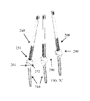
As shown in FIGs. 7C-7D, although the upper retainer 251 and the lower
retainer 252 are
configured to retain two rods 290, adjacently inserted implants 200 may be
retaining one, U-
shaped rod 290, the rod having a U-shaped bend 299 at one end thereof The
concave cavities of
the upper retainer 251 and the lower retainer 252 are toleranced so that, once
tightened in place,
the retainer 251, 252 lock the U-shaped rod 290 in place therebetween. The U-
shaped rod 290 is
configured to balance forces throughout the entire implant 200. The U-shaped
rod 290 has
bulleted tips on each of the free ends, and has a U-shaped bend 299 at a
respective other end.
The bulleted tips of the U-shaped rod 290 is configured for slidable insertion
between the lower
retainer 252 and the upper retainer 251.
In this embodiment, the lower retainer 252 can have an unthreaded internal
passage so
that the lower retainer 252 is able to slide freely over the elongated member
240. Additionally,
the underside of the lower retainer 252 is concave providing for mating and
tightening against an
engagingly shaped pedicle screw cap 261 under reduction. The upper retainer
251 has a threaded
internal passage to threadably engage the externally threaded elongated member
240. During
tightening, the internal threads of the upper retainer 251 and the external
threads of the elongated
member 240 together provide reduction to tighten the lower retainer 252 and
the upper retainer
251 against the U-shaped rod 290 and the top of the pedicle screw cap 261.
After reduction, the
upper retainer 251 is tightened further until the torsional force exceeds the
sheer threshold of the
break-away reveal 220 in the elongated member 240 to sheer away a portion of
the elongated
member 240 proximal to the break-away reveal 220.
For the FIGs. 3-7 embodiments of the implant 100, 200 of the present
invention, the drive
tool 91 includes a driver shaft 93 and a torque handle 94 with a quick release
mechanism 97.
The drive tool 91 provides that the implant 100, 200 can be tightened to a
finite torque
14
CA 02859280 2014-06-13
WO 2013/090721
PCT/US2012/069751
specification. The quick release mechanism 97 associated with the torque
handle 94 allows the
torque handle 94 to be released from the driver shaft 93. The driver shaft 93
is hollow, with a
distal tip having an internal mechanical driver design (e.g., hex) to engage
an external periphery
of the head 219 of the pedicle screw 110, 210. An internal recess at a distal
end of the quick
release mechanism 97 would also have a mechanical driver design (e.g., hex,
reverse threads) to
engage a proximal end of the elongated member 140, 240. The hollow driver
shaft 93 slides
over the elongated member 140, 240, so that the distal tip thereof engages the
head of the pedicle
screw. Then the recess at the distal end of the quick release mechanism 97 is
be attached (e.g.,
threadably engaged) to the proximal end of the elongated member 40. In this
embodiment of the
drive tool 91, the driver shaft 93 has a lever arm, facilitating driving
(turning of) the head 219 of
the pedicle screw 110, 210, by the driver shaft 93, and the torque handle 94
facilitates driving, or
turning of, the elongated member 140, 240. Here, the torque handle 94 would
rotate the
elongated member 140, 240, to slidably translate the upper retainer portion
151, 251 distally
toward the lower retainer portion 152, 252 to secure and fix a rod 190, 290
therebetween. As a
final tightening of the upper retainer portion 151, 251 against the lower
retainer portion 152, 252
another hollow driver shaft 93 can have a distal tip having an internal
mechanical driver design
(e.g., hex, teeth) to engage an external periphery of (or a top of) the upper
retainer portion 151,
251 to specifically apply a torque thereto to fix and secure a rod 190, 290.
FIGs. 8A and 8B illustrate a perspective view, and a side cross-section view,
respectively, of a molded polymer tray (kit) for housing disposable medical
instruments and
implants, along with a polymer lid for containing the instruments. The tray
can be made of a
polymer allowing gamma sterilization to enter into the tray, to sterilize the
implants and
instruments for surgical use, and to then seal the instruments and implants to
prevent
recontamination prior to opening and use. The kit can be molded to fit any
collection of
instruments and implants detailed in the present application, or any medical
instruments and
implants generally. While FIG. 8A and 8B show the tray having a single,
generally open cavity
to house the instruments and implants, another embodiment can have custom
sized and molded
cavities to specifically fit each instrument and implant.
FIG. 9 illustrates components of an automatic instrument used in spinal
surgery. The
automatic instrument includes an electronic motor 310 (high torque/low
torque), calibrated and
CA 02859280 2014-06-13
WO 2013/090721
PCT/US2012/069751
geared specifically to drive and tighten implants and pedicle screws used in
spinal surgery, such
as the pedicle screws included in, and the implants detailed in the present
invention. The motor
310 includes a switch 320 and a microprocessor 320 to control and alter gears
of the motor 310.
A low torque setting offers a medium-rpm, low torque drive function to tighten
a retainer onto an
implant of the present invention. A high torque setting offers a low-rpm, high
torque drive
function for shearing/breaking off a portion of an elongated member of
implants of the present
invention, at the break-away reveal located on the respective elongated
members. The automatic
instrument can further be a single-use, terminally sterilized device. A
battery pack 340 can
power the electronic motor 310, the switch 330, and the microprocessor 320.
The automatic
instrument can be packed into a kit, along with associated implants and
instruments, as desired,
and sterilized for single use in a sterile field.
Referring back to FIG. 3, illustrating in cross-section one implant embodiment
of the
present invention, provides just one example of a construct appropriate for
use with the
automatic instrument of FIG. 9. As detailed earlier, the implant 100 includes
a threaded
elongated member 140 having a break-away reveal 120, an upper retainer 151, a
lower retainer
152, a swivel connector head 161, a swivel ball 165, and a pedicle screw 110.
The break-away
reveal 120 provides for shearing off of a portion of the elongated member 140
at a specified
torque level. The automatic instrument provides that specified torque level.
Currently, almost all pedicle screws are hand tightened and torqued within the
vertebra to
specified limits using some type of torque-limiting handle. The polyaxial
movability of certain
embodiments of the present invention, such as implant 100 of FIG. 3, derived
from swivel ball
165 movability within the head of the pedicle, a driving of the pedicle screw
110 into a vertebra
is preferably performed using by drive tool connection generally at the head
of the pedicle (or, in
this embodiment, more particularly upon a periphery of the swivel connector
head 165). The
automatic driver of FIG. 9 can provide a tightening and torqueing function for
an end user. This
automatic instrument is a substantial improvement over the existing surgical
instruments, which
are all hand tools.
These and other advantages of the present invention will be apparent to those
skilled in
the art from the foregoing specification. Accordingly, it will be recognized
by those skilled in
the art that changes or modifications may be made to the above-described
embodiments without
16
CA 02859280 2014-06-13
WO 2013/090721
PCT/US2012/069751
departing from the broad inventive concepts of the invention. For example,
features detailed as
included in certain specific embodiments above are recognized as
interchangeable and possibly
included in other detailed embodiments. Specific dimensions of any particular
embodiment are
described for illustration purposes only. It should therefore be understood
that this invention is
not limited to the particular embodiments described herein, but is intended to
include all changes
and modifications that are within the scope and spirit of the invention.
17