Sélection de la langue

Search

Sommaire du brevet 2859349 

Énoncé de désistement de responsabilité concernant l'information provenant de tiers

Une partie des informations de ce site Web a été fournie par des sources externes. Le gouvernement du Canada n'assume aucune responsabilité concernant la précision, l'actualité ou la fiabilité des informations fournies par les sources externes. Les utilisateurs qui désirent employer cette information devraient consulter directement la source des informations. Le contenu fourni par les sources externes n'est pas assujetti aux exigences sur les langues officielles, la protection des renseignements personnels et l'accessibilité.

Disponibilité de l'Abrégé et des Revendications

L'apparition de différences dans le texte et l'image des Revendications et de l'Abrégé dépend du moment auquel le document est publié. Les textes des Revendications et de l'Abrégé sont affichés :

  • lorsque la demande peut être examinée par le public;
  • lorsque le brevet est émis (délivrance).
(12) Brevet: (11) CA 2859349
(54) Titre français: DISPOSITIF DE COMPRESSION DE FRACTURES
(54) Titre anglais: DEVICE FOR COMPRESSION ACROSS FRACTURES
Statut: Accordé et délivré
Données bibliographiques
(51) Classification internationale des brevets (CIB):
  • A61B 17/68 (2006.01)
(72) Inventeurs :
  • MIKHAIL, GEORGE (Etats-Unis d'Amérique)
  • PIERSON, GLEN (Etats-Unis d'Amérique)
(73) Titulaires :
  • DEPUY SYNTHES PRODUCTS, INC.
(71) Demandeurs :
  • DEPUY SYNTHES PRODUCTS, INC. (Etats-Unis d'Amérique)
(74) Agent: NORTON ROSE FULBRIGHT CANADA LLP/S.E.N.C.R.L., S.R.L.
(74) Co-agent:
(45) Délivré: 2021-02-09
(86) Date de dépôt PCT: 2012-12-04
(87) Mise à la disponibilité du public: 2013-06-20
Requête d'examen: 2017-11-30
Licence disponible: S.O.
Cédé au domaine public: S.O.
(25) Langue des documents déposés: Anglais

Traité de coopération en matière de brevets (PCT): Oui
(86) Numéro de la demande PCT: PCT/US2012/067748
(87) Numéro de publication internationale PCT: WO 2013090059
(85) Entrée nationale: 2014-06-13

(30) Données de priorité de la demande:
Numéro de la demande Pays / territoire Date
61/570,527 (Etats-Unis d'Amérique) 2011-12-14

Abrégés

Abrégé français

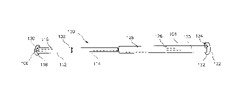
La présente invention concerne un dispositif de fixation osseuse qui comprend un premier élément s'étendant d'une première tête à une première tige le long d'un premier axe longitudinal et à l'intérieur duquel s'étend un premier canal. La première tête repose contre une partie d'os adjacente à un premier trou dans lequel la première tige est insérée. Un second élément comprend une seconde tige s'étendant le long d'un second axe longitudinal jusqu'à une seconde tête et à l'intérieur duquel s'étend un second canal, la seconde tête reposant contre une partie d'os adjacente à un second trou dans lequel la seconde tige est insérée. Le second canal est dimensionné pour recevoir en son intérieur la première tige. Un élément de mise en tension peut être inséré dans les premier et second canaux de telle sorte que la tension appliquée au niveau d'une seconde extrémité de celui-ci impartisse une force de compression à l'os dans lequel les premier et second éléments sont insérés.


Abrégé anglais

A bone fixation device includes a first element extending from a first head to a first shaft along a first longitudinal axis and having a first channel extending therethrough. The first head rests against a portion of bone adjacent to a first hole through which the first shaft is inserted. A second element includes a second shaft extending along a second longitudinal axis to a second head and having a second channel extending therethrough, the second head resting against a portion of bone adjacent to a second hole through which the second shaft is inserted. The second channel is dimensioned to receive the first shaft therein. A tensioning element is insertable through the first and second channels so that tension applied at a second end thereof imparts a compressive force to the a bone into which the first and second elements are inserted.

Revendications

Note : Les revendications sont présentées dans la langue officielle dans laquelle elles ont été soumises.


What is claimed is:
1. A bone fixation device, comprising:
a first element extending from a first head at a first end to a first shaft at
a
second end along a first central longitudinal axis and having a first channel
extending therethrough, the first head extending transverse to the first shaft
providing a first shoulder which, in an operative configuration, rests against
a
portion of bone adjacent to a first hole through which the first shaft is
inserted to
define a maximum extent to which the first element may be inserted into the
first
hole;
a second element including a second shaft extending along a second
central longitudinal axis from a third end to a second head at a fourth end
thereof
and having a second channel extending therethrough, the second head extending
transverse to the second shaft providing a second shoulder which, in an
operative
configuration, rests against a portion of bone adjacent to a second hole
through
which the second shaft is inserted to define a maximum extent to which the
second element may be inserted into the second hole, the second channel being
dimensioned to slidably receive the first shaft therein; and
a tensioning element insertable through the first and second channels, the
tensioning element including a first end sized to prevent the first end from
entering one of the first and second channels so that, tension applied at a
second
end of the tensioning element imparts a compressive force to the first and
second
elements and, consequently to a bone into which the first and second elements
are
inserted.
2. The bone fixation device of claim 1, wherein the first head comprises a
first opening
Page -8-

positioned adjacent to the first channel, the first opening being configured
and
dimensioned to receive a second end of the tensioning member therethrough and
prevent
movement of the first end of the tensioning member therepast.
3. The bone fixation device of claim 2, wherein the second head comprises a
second
opening positioned adjacent to the second channel, the second opening being
configured
and dimensioned to receive the second end of the tensioning member
therethrough.
4. The bone fixation device of claim 2, wherein the first opening is angled
at an angle
smaller than 90 relative to the first central longitudinal axis.
5. The bone fixation device of claim 3, wherein the second opening is
angled at an angle
smaller than 90 relative to the second central longitudinal axis.
6. The bone fixation device of claim 1, further comprising a first
countersunk portion on the
first shoulder.
7. The bone fixation device of claim 6, further comprising a second
countersunk portion on
the second shoulder.
8. A bone fixation device, comprising:
a first element extending from a first head at a first end to a first shaft at
a
second end along a first central longitudinal axis and having a first channel
extending therethrough, the first head extending transverse to the first shaft
providing a first shoulder which, in an operative configuration, rests against
a
portion of bone adjacent to a first hole through which the first shaft is
inserted to
define a maximum extent to which the first element may be inserted into the
first
hole; and
Page -9-

a second element including a second shaft extending along a second
central longitudinal axis from a third end to a second head at a fourth end
thereof
and having a second channel extending therethrough, the second head extending
transverse to the second shaft providing a second shoulder which, in an
operative
configuration, rests against a portion of bone adjacent to a second hole
through
which the second shaft is inserted to define a maximum extent to which the
second element may be inserted into the second hole, the second channel being
dimensioned to slidably receive the first shaft therein, the first and second
elements being configured to apply a compressible force to a bone into which
the
first and second elements are inserted.
9. The bone fixation device of claim 8, wherein the first and second
channels are configured
and dimensioned to receive a tensioning element therethrough, the tensioning
element
including a first end sized to prevent the first end from entering one of the
first and
second channels so that tension applied at a second end of the tensioning
element imparts
the compressive force to the first and second elements and, consequently to
the bone.
10. The bone fixation device of claim 9, wherein the first head comprises a
first opening
positioned adjacent to the first channel, the first opening being configured
and
dimensioned to receive a second end of the tensioning member therethrough and
prevent
movement of the first end of the tensioning member therepast.
11. The bone fixation device of claim 10, wherein the second head comprises
a second
opening positioned adjacent to the second channel, the second opening being
configured
and dimensioned to receive the second end of the tensioning member
therethrough.
12. The bone fixation device of claim 10, wherein the first opening is
angled at an angle
smaller than 90° relative to the first central longitudinal axis.
Page -10-

13. The bone fixation device of claim 11, wherein the second opening is
angled at an angle
smaller than 90° relative to the second central longitudinal axis.
14. The bone fixation device of claim 8, further comprising a first
countersunk portion on the
first shoulder.
15. The bone fixation device of claim 14, further comprising a second
countersunk portion on
the second shoulder.
16. A bone fixation device, comprising:
a first element including a first head and a first shaft extending along a
first central axis
from a first end connected to the first head to a second end, the first
element including a
first channel extending therethrough, the first head extending transverse to
the first shaft
to provide a first shoulder which, in an operative configuration, rests
against a portion of
bone adjacent to a first hole through which the first shaft is inserted to
define a maximum
extent to which the first element may be inserted into the first hole, the
first head
including a first opening extending therethrough adjacent to the first
channel;
a second element including a second head and a second shaft extending along a
second
central axis from a first end connected to the second end to a second end, the
second
element including a second channel extending therethrough, the second head
extending
transverse to the second shaft to provide a second shoulder which, in an
operative
configuration, rests against a portion of bone adjacent to a second hole
through which the
second shaft is inserted to define a maximum extend to which the second
element may be
inserted into the second hole, the second channel sized and shaped to receive
the first
shaft therein; and
a tensioning element insertable through the first opening and through the
first and second
channels, the tensioning element including a first end sized to prevent the
first end from
passing through the first opening so that, tension applied at a second end of
the tensioning
Page -11-

element applies a compressive force to a bone through which the first and
second
elements are inserted.
17. The device of claim 16, wherein the first opening extends through the
first head along an
axis substantially parallel to the first central longitudinal axis.
18. The device of claim 16, wherein the first opening extends through the
first head at an
angle smaller than 90 degrees relative to the first central longitudinal axis.
19. The device of claim 16, wherein the second head includes a second
opening extending
therethrough adjacent to the second channel, the second opening sized and
shaped to
permit the second end of the tensioning element to be passed therethrough.
20. The device of claim 19, wherein the second opening extends through the
second head
along an axis substantially parallel to the second central longitudinal axis.
21. The device of claim 19, wherein the second opening extends through the
second head at
an angle smaller than 90 degrees relative to the second central longitudinal
axis.
22. The device of claim 16, wherein the first head includes a first
countersunk portion.
23. The device of claim 16, wherein the second head includes a second
countersunk portion.
Page -12-

Description

Note : Les descriptions sont présentées dans la langue officielle dans laquelle elles ont été soumises.


CA 02859349 2014-06-13
WO 2013/090059
PCT/US2012/067748
Device for Compression Across Fractures
Inventors: George Mikhail and Glen Pierson
Background Information
Fractures of the pelvis and, more specifically, of the sacroiliac joint are
often treated by inserting
a fixation device across the fracture site. Present fixation systems and
methods are generally
directed to the insertion of one or more sacral bars or cancellous screws
across the fracture site.
The sacral bars are formed as elongated planar rods passed through the pelvis
posterior to the
sacrum until a free end of the rod extends out of an opposing wall of the
pelvis. Threaded nuts
are then screwed onto the ends of the sacral bar to create and maintain
compression of the pelvis.
Cancellous screws can be inserted to span across the pelvis or can be inserted
from either side of
the pelvis to maintain the stability of the sacroiliac joint. However, these
screws rely heavily on
an overall strength of the bone and thread purchase to maintain the
compression of the pelvis.
These devices are therefore susceptible to failure due to loss of bone
strength (e.g., due to
osteoporosis, etc.), 'oosening of the threaded bolts and/or a loss of bony
purchase (e.g., through
rotational and/or longitudinal movement of the sacral bars within the bone).
Summary of the Invention
The present invention is directed to a bone fixation device comprising a first
element extending
from a first head at a first end to a first shaft at a second end along a
first central longitudinal axis
and having a first channel extending therethrough, the first head extending
transverse to the first
shaft providing a first shoulder which, in an operative configuration, rests
against a portion of
bone adjacent to a first hole through which the first shaft is inserted to
define a maximum extent
to which the first element may be inserted into the hole. The bone fixation
device also comprises
a second element including a second shaft extending along a second central
longitudinal axis
from a third end to a head at a fourth end thereof and having a second channel
extending
therethrough, the second head extending transverse to the second shaft
providing a second
Page -1-

CA 02859349 2014-06-13
WO 2013/090059
PCT/US2012/067748
shoulder which, in an operative configuration, rests against a portion of bone
adjacent to a
second hole through which the second shaft is inserted to define a maximum
extent to which the
second element may be inserted into the second hole, the second channel being
dimensioned to
slidably receive the first shaft therein. The bone fixation device also
comprises a tensioning
element insertable through the first and second channels, the tensioning
element including a first
end sized to prevent the first end from entering one of the first and second
channels so that,
tension applied at a second end of the tensioning element imparts a
compressive force to the first
and second elements and, consequently to a bone into which the first and
second elements are
inserted.
Brief Description of the Drawings
Fig. 1 shows a first perspective view of a exemplary bone fixation element
according to the
present invention in a first configuration;
Fig. 2 shows a perspective view of the bone fixation element of Fig. 1 in a
second configuration;
Fig. 3 shows a second perspective view of the bone fixation element of Fig. 1;
Fig. 4 shows a perspective view of the bone fixation element of Fig. 1 in an
implanted
configuration; and
Fig. 5 shows a side view of the bone fixation element of Fig. 1 in an
implanted configuration.
Detailed Description
The present invention may be further understood with reference to the
following description and
the appended drawings, wherein like elements are referred to with the same
reference numerals.
The present invention relates generally to devices and methods for the
fixation of a fractured or
Page -2-

CA 02859349 2014-06-13
WO 2013/090059
PCT/US2012/067748
otherwise damaged pelvic bone. Specifically, the present invention relates to
methods and
devices for inserting a bone fixation element into the bone. The exemplary
bone fixation
element according to the invention comprises a first elongated element and a
second elongated
element, each extending along a longitudinal axis. In an operative
configuration, the first and
second elements are inserted through first and second lateral openings
provided on opposing
sides of a pelvic bone. In one embodiment, the first and second lateral
openings can be two ends
of a single hole formed by drilling completely across the pelvis. In another
embodiment, two
openings may be drilled on opposing walls of the pelvis. A free end of the
first element is then
inserted into a channel extending through the second element until the first
and second elements
are securely seated against the pelvic bone. A cable is then inserted through
the first and second
elements. A first end of the cable comprises a cable stop configured to
lockingly engage an
opening on a lateral head of the first element. The cable is then locked in
position at a lateral end
of the second element using a crimp to secure the first and second elements in
a desired position
relative to one another and compress the fractured bone, as will be described
in greater detail
later on. It is noted that although the exemplary system and method are
discussed with respect to
a sacroiliac fixation system and method, the invention may be used in any
other bone fixation
procedure in any other bone of the body by modifying the dimensions and shape
of the apparatus
to suit the particular anatomy. The term "medial" as used herein refers to a
direction
approaching a medial plane of a body in an operative configuration while the
term "lateral"
refers to a direction extending away from the medial plane in a right and left
direction.
As shown in Figs. 1 - 5, a bone fixation device 100 according to an exemplary
embodiment of
the invention comprises a first element 102 and a second element 104. The
first element 102
extends from a lateral end 106 to a medial end 108 along a central
longitudinal axis 110. The
first element 102 according to this embodiment is substantially cylindrical
and comprises a
lateral body portion 112 having a first outer diameter and a medial body
portion 114 having a
second outer diameter, the second outer diameter being smaller than the first
outer diameter. An
elongated first channel 116 extends through the first element 102 from the
lateral end 106 to the
medial end 108. The first channel 116 is in longitudinal aligmnent with the
longitudinal axis 110
Page -.3-

CA 02859349 2014-06-13
WO 2013/090059
PCT/US2012/067748
and is configured and dimensioned to receive a cable 200 therethrough, as will
be described in
greater detail later on. The lateral end 106 comprises an increased diameter
head 118 having an
oblong cross-sectional shape. It is noted, however, that any other cross-
sectional shape (e.g.,
oval, circular, rectangular, etc.) may be used without deviating from the
scope of the invention.
The head 118 also comprises an opening 120 extending therethrough, a hole axis
of the opening
120 extending substantially parallel to the longitudinal axis 110. In another
exemplary
embodiment, the hole axis of the opening 120 may extend at any other angle
relative to the axis
110. The opening 120 is positioned adjacent to the channel 116. As shown in
Figs. 4 - 5, the
head 118 may also comprise a countersunk portion 121 configured to aid in
manipulation of the
cable 200, as will also be described in greater detail below.
The second element 104 extends from a lateral end 122 to a medial end 124
along the central
longitudinal axis 110. The second element 104 according to this embodiment is
substantially
cylindrical in shape and comprises a substantially uniform outer diameter
which is substantially
equivalent to the first outer diameter of the lateral body portion 112.
However, those skilled in
the art will understand that the first and second elements 102, 104,
respectively, may take any
desired shape so long as the medial body portion 114 is slidably receivable
within an elongated
second channel 126 extending through the second element 104. The second
channel 126 extends
from the lateral end 122 to the medial end 124 in longitudinal alignment with
the longitudinal
axis 110 and is configured and dimensioned to permit insertion of the medial
body portion 114
thereinto. In one exemplary embodiment, the channel 126 has a substantially
uniform diameter
substantially equivalent to the outer diameter of the medial body portion 114
with a slight
clearance to permit the medial body portion 114 to slide therein. In another
exemplary
embodiment, as shown in Fig. 3, the channel 126 comprises a medial channel
portion 128 and a
lateral channel portion 130. The medial channel portion 128 has a diameter
substantially
equivalent to or greater than second outer diameter of the medial body portion
114 and smaller
than the first outer diameter of the lateral body portion 112. This
configuration permits the
insertion of the medial body portion 114 into the channel 126 while preventing
the lateral body
portion 112 from being inserted therein. In an exemplary embodiment, the first
and second
Page -4-

CA 02859349 2014-06-13
WO 2013/090059
PCT/US2012/067748
portions 102, 104 are dimensioned so that, when inserted to an operative
configuration, the
medial body portion 114 is seated within the medial channel portion 128 with
enough overlap to
maintain stability. Varying a length of the overlap allows adjustment of the
length of the device
100 to account for variations in anatomy in different patients. In another
embodiment, the device
100 may be provided in a variety of lengths so that a physician may select a
device having a
length range conforming to the requirements of a particular procedure. In a
preferred
embodiment, the device 100 may be configured to prevent the medial body
portion 114 from
being fully seated in the medial channel portion 128. That is, by having the
medial body portion
114 only partially seated in the medial channel portion 128, a greater amount
of compression
may be applied via the cable 200, as will be described in greater detail later
on. The lateral
channel portion 130 has substantially the same diameter as the first channel
116 so that the cable
200 inserted through the device 100 follows a smooth, substantially
unobstructed path. The
lateral end 122 comprises an increased diameter head 132 having an oblong
cross-sectional
shape similar to the shape of the head 118. It is noted, however, that the
head 132 may comprise
any other shape without deviating from the scope of the invention. The head
132 comprises an
opening 134 extending therethrough, a hole axis of the opening 134 extending
substantially
parallel to the longitudinal axis 110. As with the opening 120, the hole axis
of the opening 134
may also extend at any angle relative to the axis 110.
In accordance with an exemplary method according to the invention, a physician
or other user
makes incisions open to the right and left lateral walls of a pelvis. The
fracture is then reduced
and provisionally stabilized using, for example, Kirschner wires, as those
skilled in the art will
understand. A drill may then be used to form at least one longitudinal hole
through the pelvis. A
guide wire may first be inserted in the desired portion of the bone in a
target insertion
orientation. A cannulated drill may then be guided over the guide wire to open
the bone to a
desired diameter selected to accommodate the device 100, as those skilled in
the art will
understand. In an exemplary embodiment, two holes may be drilled through the
pelvis across the
fracture to receive two devices 100, although any number of holes may be
drilled to conform to
the requirements of the particular procedure, as those skilled in the art will
understand. The
Page -5-

CA 02859349 2014-06-13
WO 2013/090059
PCT/US2012/067748
cable 200 having the cable stop 202 on a first end thereof is then inserted
into the opening 120 of
the first element 102. The cable stop 202 may be an enlarged end portion of
the cable 200
having a diameter greater than a diameter of the opening 120. In an exemplary
embodiment, the
cable stop 202 is inserted into the opening 120 from a medial direction so
that when the first
element 102 is positioned in the bone, the cable stop 202 is positioned toward
the bone. As those
skilled in the art will understand, this configuration minimizes stresses
applied to the cable stop
202 in an operative configuration and helps to prevent loosening of the cable
200 relative to the
bone. The first and second elements 102, 104 may then be inserted into the
drilled hole from the
left and right walls of the pelvis, respectively, until the medial body
portion 114 is seated within
the medial channel portion 128, as described in greater detail earlier. In
this configuration, the
heads 118, 132 are in contact with the pelvis and the cable stop 202 is
positioned adjacent the
bone, as shown in Fig. 3. The cable stop 202 is seated within the concave
portion of the head
118 so the head 118 is in direct contact with the bone without interference
from the cable stop
202. The free end of the cable 200 (not shown) is then inserted into the
channel 116 from the
lateral end 106, forming a loop 204 adjacent the head 118. As those skilled in
the art will
understand, the cable 200 may be configured and dimensioned to minimize a
protrusion of the
loop 204 out of the head 118 therefore minimizing a profile of the implanted
device 100. The
loop 204 aids in removal of the device 100 from the body, as will be described
in greater detail
later on. The cable 200 is guided through the channel 116 and channel 126
until the free end
exits the lateral end 122. The free end of the cable 200 is then inserted into
the opening 134
from the lateral end. A crimp is then advanced over the free end of the cable
200 and advanced
until it contacts the head 132 of the second element 104, The crimp may be any
crimp known in
the art. A tensioning mechanism threaded over the free end of the cable 200 is
then operated as
would be understood by those skilled in the art to apply a desired tension to
the cable
consequently applying a desired compressive force to the bone. The crimp is
then crushed in a
known manner to maintain the desired tension on the cable and the free portion
of the cable 200
extending away from the crimp is trimmed. As would be understood by those
skilled in the art,
the countersunk portion 121 provides a space for into which the cable cutter
may be advanced to
allow a cable cutting device to snip the cable close in minimizing the
protrusion of the free end
Page -6-

CA 02859349 2014-06-13
WO 2013/090059
PCT/US2012/067748
of the cable 200.
A physician may decide to remove the device 100 from the body after a
predetermined amount
of time has elapsed (e.g., once the bone has healed, etc.). To remove the
device, a cable cutting
mechanism may be used to cut the loop 204, thereby removing the compressive
force applied on
the bone by the device 100. The device 100 and cable 200 may then be removed
from the body.
It will be apparent to those skilled in the art that various other
modifications and variations may
be made in the structure and the methodology of the present invention, without
departing from
the spirit or scope of the invention. For example, the exemplary system and
method disclosed
herein may be used for the treatment of any bone fracture wherein compression
is required and
opposing ends of the fractured bone are accessible to the physician. For
example, the exemplary
system and method may be used for the fixation of fractures of a patella,
condyle, etc., wherein
the compression may be aided by any number of additional bone fixation devices
(e.g.,
intramedullary nail) without deviating from the scope of the invention. Thus,
it is intended that
the present invention cover modifications and variations of the invention
provided that they
come within the scope of the appended claims and their equivalents.
Page -7-

Dessin représentatif
Une figure unique qui représente un dessin illustrant l'invention.
États administratifs

2024-08-01 : Dans le cadre de la transition vers les Brevets de nouvelle génération (BNG), la base de données sur les brevets canadiens (BDBC) contient désormais un Historique d'événement plus détaillé, qui reproduit le Journal des événements de notre nouvelle solution interne.

Veuillez noter que les événements débutant par « Inactive : » se réfèrent à des événements qui ne sont plus utilisés dans notre nouvelle solution interne.

Pour une meilleure compréhension de l'état de la demande ou brevet qui figure sur cette page, la rubrique Mise en garde , et les descriptions de Brevet , Historique d'événement , Taxes périodiques et Historique des paiements devraient être consultées.

Historique d'événement

Description Date
Accordé par délivrance 2021-02-09
Inactive : Page couverture publiée 2021-02-08
Inactive : Lettre officielle 2021-01-04
Un avis d'acceptation est envoyé 2021-01-04
Inactive : Q2 réussi 2020-12-09
Inactive : Approuvée aux fins d'acceptation (AFA) 2020-12-09
Inactive : Acc. rétabl. (dilig. non req.)-Posté 2020-12-07
Modification reçue - modification volontaire 2020-11-13
Préoctroi 2020-11-13
Retirer de l'acceptation 2020-11-13
Taxe finale payée et demande rétablie 2020-11-13
Inactive : Taxe finale reçue 2020-11-13
Requête en rétablissement reçue 2020-11-13
Réputée abandonnée - les conditions pour l'octroi - jugée non conforme 2020-08-31
Inactive : COVID 19 - Délai prolongé 2020-08-19
Inactive : COVID 19 - Délai prolongé 2020-08-06
Inactive : COVID 19 - Délai prolongé 2020-07-16
Inactive : COVID 19 - Délai prolongé 2020-07-02
Inactive : COVID 19 - Délai prolongé 2020-06-10
Inactive : COVID 19 - Délai prolongé 2020-05-28
Inactive : COVID 19 - Délai prolongé 2020-05-14
Inactive : COVID 19 - Délai prolongé 2020-04-28
Inactive : COVID 19 - Délai prolongé 2020-03-29
Représentant commun nommé 2019-10-30
Lettre envoyée 2019-09-16
Un avis d'acceptation est envoyé 2019-09-16
Inactive : Approuvée aux fins d'acceptation (AFA) 2019-08-19
Inactive : Q2 réussi 2019-08-19
Entrevue menée par l'examinateur 2019-08-02
Modification reçue - modification volontaire 2019-07-30
Modification reçue - modification volontaire 2019-04-25
Inactive : Rapport - Aucun CQ 2018-10-25
Inactive : Dem. de l'examinateur par.30(2) Règles 2018-10-25
Lettre envoyée 2017-12-07
Toutes les exigences pour l'examen - jugée conforme 2017-11-30
Exigences pour une requête d'examen - jugée conforme 2017-11-30
Requête d'examen reçue 2017-11-30
Lettre envoyée 2015-07-14
Inactive : Page couverture publiée 2014-09-10
Inactive : CIB en 1re position 2014-08-18
Inactive : Notice - Entrée phase nat. - Pas de RE 2014-08-18
Inactive : CIB attribuée 2014-08-18
Demande reçue - PCT 2014-08-18
Exigences pour l'entrée dans la phase nationale - jugée conforme 2014-06-13
Demande publiée (accessible au public) 2013-06-20

Historique d'abandonnement

Date d'abandonnement Raison Date de rétablissement
2020-11-13
2020-08-31

Taxes périodiques

Le dernier paiement a été reçu le 2020-11-05

Avis : Si le paiement en totalité n'a pas été reçu au plus tard à la date indiquée, une taxe supplémentaire peut être imposée, soit une des taxes suivantes :

  • taxe de rétablissement ;
  • taxe pour paiement en souffrance ; ou
  • taxe additionnelle pour le renversement d'une péremption réputée.

Les taxes sur les brevets sont ajustées au 1er janvier de chaque année. Les montants ci-dessus sont les montants actuels s'ils sont reçus au plus tard le 31 décembre de l'année en cours.
Veuillez vous référer à la page web des taxes sur les brevets de l'OPIC pour voir tous les montants actuels des taxes.

Historique des taxes

Type de taxes Anniversaire Échéance Date payée
Taxe nationale de base - générale 2014-06-13
TM (demande, 2e anniv.) - générale 02 2014-12-04 2014-06-13
Enregistrement d'un document 2015-06-25
TM (demande, 3e anniv.) - générale 03 2015-12-04 2015-11-05
TM (demande, 4e anniv.) - générale 04 2016-12-05 2016-11-09
TM (demande, 5e anniv.) - générale 05 2017-12-04 2017-11-08
Requête d'examen - générale 2017-11-30
TM (demande, 6e anniv.) - générale 06 2018-12-04 2018-11-05
TM (demande, 7e anniv.) - générale 07 2019-12-04 2019-11-11
TM (demande, 8e anniv.) - générale 08 2020-12-04 2020-11-05
Rétablissement 2021-08-31 2020-11-13
Taxe finale - générale 2020-03-30 2020-11-13
TM (brevet, 9e anniv.) - générale 2021-12-06 2021-11-03
TM (brevet, 10e anniv.) - générale 2022-12-05 2022-11-02
TM (brevet, 11e anniv.) - générale 2023-12-04 2023-10-31
TM (brevet, 12e anniv.) - générale 2024-12-04 2023-12-07
Titulaires au dossier

Les titulaires actuels et antérieures au dossier sont affichés en ordre alphabétique.

Titulaires actuels au dossier
DEPUY SYNTHES PRODUCTS, INC.
Titulaires antérieures au dossier
GEORGE MIKHAIL
GLEN PIERSON
Les propriétaires antérieurs qui ne figurent pas dans la liste des « Propriétaires au dossier » apparaîtront dans d'autres documents au dossier.
Documents

Pour visionner les fichiers sélectionnés, entrer le code reCAPTCHA :


Pour visualiser une image, cliquer sur un lien dans la colonne description du document. Pour télécharger l'image (les images), cliquer l'une ou plusieurs cases à cocher dans la première colonne et ensuite cliquer sur le bouton "Télécharger sélection en format PDF (archive Zip)" ou le bouton "Télécharger sélection (en un fichier PDF fusionné)".

Liste des documents de brevet publiés et non publiés sur la BDBC .

Si vous avez des difficultés à accéder au contenu, veuillez communiquer avec le Centre de services à la clientèle au 1-866-997-1936, ou envoyer un courriel au Centre de service à la clientèle de l'OPIC.


Description du
Document 
Date
(aaaa-mm-jj) 
Nombre de pages   Taille de l'image (Ko) 
Description 2014-06-12 7 381
Revendications 2014-06-12 5 199
Dessins 2014-06-12 2 29
Abrégé 2014-06-12 1 62
Dessin représentatif 2014-08-18 1 4
Revendications 2019-04-24 4 121
Revendications 2019-07-29 4 120
Revendications 2020-11-12 5 184
Dessin représentatif 2021-01-12 1 3
Avis d'entree dans la phase nationale 2014-08-17 1 206
Rappel - requête d'examen 2017-08-06 1 126
Accusé de réception de la requête d'examen 2017-12-06 1 174
Avis du commissaire - Demande jugée acceptable 2019-09-15 1 162
Courtoisie - Lettre d'abandon (AA) 2020-10-25 1 547
Courtoisie - Accusé réception du rétablissement (requête d’examen (diligence non requise)) 2020-12-06 1 405
Demande de l'examinateur 2018-10-24 3 152
PCT 2014-06-12 7 224
Requête d'examen 2017-11-29 3 92
Modification / réponse à un rapport 2019-04-24 7 211
Modification / réponse à un rapport 2019-07-29 7 197
Note relative à une entrevue 2019-08-01 1 18
Rétablissement / Modification / réponse à un rapport 2020-11-12 16 758
Taxe finale 2020-11-12 16 758
Courtoisie - Lettre du bureau 2021-01-03 1 169