Note : Les descriptions sont présentées dans la langue officielle dans laquelle elles ont été soumises.
CA 02859515 2014-06-16
WO 2013/103299 PCT/NL2013/050001
Electrostatic coalescer and method for electrostatic coalescence
The invention relates to a device for electrostatic coalescence of liquid
particles in a
flowing fluid mixture, especially for coalescence of water in an flowing
water/oil fluid
mixture, comprising: a tube having a feed opening located at the front side of
the tube
and a discharge opening located on the opposite side of the tube; power means
for
providing a current; and at least two electrodes located inside the tube
electrically
connected to the power means. The invention also relates to a method for
electrostatic
coalescence of liquid particles in a flowing fluid mixture, especially for
coalescence of
water in a flowing water/oil fluid mixture.
Separation of liquid flows with strong oil-water emulsions is known. Typically
known
electrostatic coalescers are vessel-based internals in large vessels. High
viscosity crudes
and heavy crude oils typically require long residence times for adequate
liquid-liquid
separation even with electrostatics in combination with high operating
temperatures,
thus resulting in a bulky and heavy vessel. Such step in the separation is
also referred to
as to "breaking the emulsion" and is, among others known from US 7,351,320.
wherein
the augmentation of the separation of an emulsion is disclosed making use of
an AC
voltage source employing a specific modulation pattern.
The intention of the present invention is to further augment the inline
coalescence in
reduced size process equipment of a fluid mixture at enhanced efficiency and
effectively.
The present invention provides a device for electrostatic coalescence of
liquid particles
in a flowing fluid mixture, of the type according the preamble that also
comprises a
least one arrangement with flow guide vanes arranged in the tube, positioned
in between
the opened infeed side and an opposite opened outfeed side, for forcing the
movement
to the fluid mixture flowing through the tube, possibly with imparting a
rotation to it.
Different from the teachings according the prior art wherein a mere linear
flow of the
mixture in the vicinity of the electrodes is required the arrangement with
flow guide
vanes can force the movement of the fluid in the vicinity of the electrodes
such that it
either provides a rotating flow or that it reduces the turbulence. This
guidance of the
mixture, that leads away from the existing coalescers of this type, results in
the ability
CA 02859515 2014-06-16
WO 2013/103299
PCT/NL2013/050001
2
of an electrostatic coalescer according the present invention to provide a
better
coalescing performance than a prior art electrostatic coalescer. The
arrangement with
flow guide vanes may for instance be implemented as a swirl element. Due to
the
turbulence the chance for contact/meeting of liquid particles to coalesce with
other
liquid particles to coalesce increases thus the coalescing effect may be
enhanced at least
as the turbulence is not, at least not in a serious rate, breaking up already
coalesced
particles. The arrangement with flow guide vanes can reduce the turbulence
effects such
that breaking up will not occur or it can generate centrifugal forces, acting
along the
axis of the pipe on the polarized liquid particles to coalesce (droplets).
These particles
will start to slip with the continuous phase with the slip velocity depending
on the
particle size. The differences in slip velocities for different sized
particles will further
support (increase) the coalescence in addition to coalescence due to any
existing
turbulent fluctuations. An option is to couple two or more coalescing devices
according
the present invention in line, as to coalesce the mixture subsequently plural
times. The
coalescence by means of electrostatics supported with induced swirl is
preferably
conducted on viscous liquid flow holding no gas or only low levels of gas.
In an embodiment the power means are AC power means to provide an alternating
current. With such an alternating electric field the particle to coalesce may
be given
multiple impacts so to be more or less "shaken" which also further supports
the
coalescing effect sought for.
At least one of the electrodes may be embodied as an arrangement with flow
guide
vanes. By combining the arrangement with flow guide vanes with at least one of
the
electrodes less parts are required as well as that the guiding the movement of
the
mixture and providing an electric field to act on the mixture may both be
executed
efficiently.
The arrangement with flow guide vanes may comprise at least one helical blade
or, as
an alternative may comprise plural helical blades, dependent on the
circumstances the
electrostatic coalescer according the present invention is to be used. To
impart a
rotational movement to the mixture without providing too much turbulence to
the fluid
flow the guide vanes can start and/or end in line with the axial direction of
the pipe. A
linear flowing fluid can be "picked up" smoothly by a guide vane that starts
in line with
CA 02859515 2014-06-16
WO 2013/103299 PCT/NL2013/050001
3
the axial direction of the pipe. The same applies for a guide vane ending in
line with the
axial direction of the pipe; such guide vane ending provides a smooth
transition from
the rotating fluid flow to an, again, linear fluid flow. The helical blades
may uniformly
be distributed with e.g. subsequent electrified and grounded blades. As to
prevent the
tube being electrically loaded both electrodes may be electrically insulated
from the
tube.
Two different electrodes may act as two cooperating helical blades. Again such
construction is efficient as the blades combine two different functions but
also the
distance between two electrodes may be controlled.
In a further embodiment of the electrostatic coalesce according the present
invention
plural arrangements with flow guide vanes may be provided in co-centric tubes.
As the
guiding of the flow is so imparted in multiple annuli the average distance of
a coalesced
particle to the inner wall of a tube is limited if compared to a single tube
coalesce with
the same capacity.
In a specific embodiment a feed pipe is connecting to the feed opening such
that the
axial direction of the feed pipe at the connection with the tube has at least
a component
that is in line with the axial direction of the tube. In a more specific
embodiment of such
connection the feed pipe at the connection with the tube is in line with the
axial
direction of the tube; so to be an axial feed. The at least axial component in
the flow
direction of the fluid mixture prevents too much turbulence in the fluid flow
that would
negatively influence the coalescence sought for.
In another embodiment the tube substantially may have the form of a cylinder
jacket.
Such tubes are common available as shelf parts and is also beneficial to the
control of
the flow pattern and to any subsequent separation separation processes. The
tube can be
oriented in any position, for instance horizontally or vertically. A first
separation can
occur in axial direction along the pipe walls through a pipe section with the
arrangement
with flow guide vanes and further downstream. For example a free water phase
may be
extracted from the liquid flow and the remaining liquid, primarily crude oil
with low
percentage of water, will enter smoothly an associated downstream separator
vessel or
pipe that can efficiently fulfil a subsequent phase separation of the
fractions.
CA 02859515 2014-06-16
WO 2013/103299 PCT/NL2013/050001
4
The at least one arrangement with flow guide vanes may be arranged in a tube
with a
length of 0,1 ¨ 2 meters, and over least 80% of the length of the tube
arrangements with
flow guide vanes may be provided. The device may for example be embedded
inside the
pipe or in an inlet pipe section of a small separator vessel. With only
limited
construction lengths of the device according the recent invention beneficial
result may
be realised.
For effective construction and maintenance the power means for providing an
alternating current may be located outside the tube. Such power means may
provide an
alternating current of 50 ¨ 600 Hz, while the field intensity may be 2 - 6
kV/cm.
For a suitable functioning of the device the arrangement with flow guide vanes
may at
least partially be covered with an electrically insulating coating, like for
instance a
Teflon coating.
The present invention also provides a method for electrostatic coalescence of
liquid
particles in a flowing fluid mixture, especially for coalescence of water in a
flowing
water/oil fluid mixture, comprising the steps of: A) feeding the fluid mixture
to a pipe;
B) providing an electric field to act on the mixture flowing through the pipe;
C) guiding
the mixture flowing through the tube either to impart a rotating movement to
the fluid or
to reduce the turbulence levels to prevent break-up; and D) discharging the at
least
partial coalesced mixture from the tube. With this method the advantages as
present
before in relation to the electrostatic coalescence device can be realised,
which are here
included by way of reference. To speed up the process the steps B) and C) may
be
combined. And as for the duration of the steps B) and C); these steps may take
for
instance 0,1 ¨ 10 seconds, preferably 0,5 ¨ 5 seconds and the power may be
provided as
an alternating current of 50 ¨ 600 Hz at 2 ¨ 6 kV/cm. Within such operative
ranges
positive effects of the present invention are envisaged.
Later on during the process of acting an electric field on the mixture the
guiding of the
fluid may be diminished, e.g. by changing the speed of at least one
arrangement with
flow guide vanes or by diminishing the number of blades of an, at the start of
the
process, plural bladed arrangement with flow guide vanes. Earlier ending of at
least one
CA 02859515 2014-06-16
WO 2013/103299
PCT/NL2013/050001
of the blades, can lead to setting/polishing of the at least partial coalesced
mixture. The
invention provides a method to break emulsions rapidly making use of inline
arrangement (pipe based), thus with a minimum of hold-up volume.
5 Furthermore the at least partial coalesced mixture discharged from the
tube may be
provided a subsequent separation processing. In practise e.g. a multi staged
separation
processing according the present invention may be executed and/or other down
stream
pipe-based separator or vessel type of separator may be used for subsequent
processing
of the at least partially coalesced fluid mixture. A further embodiment
provides a
coalescer with plural sections, depending on the emulsion stability.
The invention will be further elucidated herein below on the basis of the non-
limitative
exemplary embodiments shown in the following figures. Herein:
figure 1 is a schematic cross-section view of an embodiment of a coalescence
device according to the present invention;
figure 2 is a schematic cross-section view of an alternative embodiment of a
coalescence device according to the invention;
figure 3 is a detailed view of arrangement with flow guide vanes as part of an
embodiment of a coalescence device according to the present invention;
figures 4A and 4B show cross-sections through two embodiments of
coalescence devices according to the present invention;
figure 5 a three-dimensional view of an alternative embodiment of a
coalescence
device according to the present invention, and
figure 6 shows a cross-section through a further alternative embodiment of a
coalescence device according to the present invention.
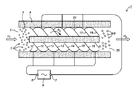
Figure 1 shows an electrostatic coalescence device 1 for liquid particles 2 in
a flowing
fluid mixture 3 that a fed according to arrow Pi to a tube 4 having a feed
opening 5. In
the tube 4 helical blades 10 ¨ 18 are arranged that impart a rotational
movement
according arrow P2 to the fluid mixture 3. The fluid mixture 3 that is fed
(Pi) to the
coalescence device 1 comprises small relative liquid particles 2 that have a
different
composition compared to the main component of the fluid mixture 3, for
instance water
particles 2 in an oil flow. The water particles 2 (e.g. an emulsion of oil and
water) are
randomly distributed in the mixture 3 while entering the tube 4 at the feed
opening 5.
CA 02859515 2014-06-16
WO 2013/103299 PCT/NL2013/050001
6
The helical blades 10 ¨ 18 not only impart a rotational movement to the fluid
mixture 3,
the helical blades 10 ¨ 18 are also providing an electric field to act on the
mixture 3.
The helical blades 10 ¨ 18 are alternately electrically connected to the poles
6, 7 of an
electric power source 8, so the helical blades 10, 12, 14, 16 and otherwise
the helical
blades 11, 13, 15, 17 also act as electrodes. The combination of the
rotational movement
to the fluid mixture 3 with the electric field acting on the mixture 3 results
in the
effective coalescence of the water particles 2 resulting in substantially
larger water
particles 9 when the mixture 3 leaves (P3) the discharge opening 20 of the
tube 4
compared to the size of the water particles 2 at the feed opening 5. An even
further
effect that is reached with the electrostatic coalescence device 1 is that the
rotational
movement according arrow P2 of the fluid mixture 3 also results in a further
pre-
separation of the water particles 9 from the main flow of the fluid mixture 3.
Due to the
rotation the heavier fraction will be urged towards the inner wall 21 of the
tube 4 while
the lighter fraction (the water particles 9 in this example) will concentrate
more to the
centre of the tube 4. this 3effect is illustrated in that the water particles
9 when leaving
the tube 4 (P3) are more concentrated to the centre of the fluid flow.
Figure 2 shows an electrostatic coalescence device 30 with a tube 31 wherein
electrostatic arrangements with flow guide vanes 32 are arranged that are
connected to a
power source 33. For so far the device 30 is more or less in line with the
electrostatic
coalescence device 1 as shown in figure 1. However in the coalescence device
30 a
subsequent pre-separator 34 is also arranged in the tube 31. A co-centric
additional
inner tube 35 is located behind (seen in the direction of the fluid flow) the
electrostatic
arrangements with flow guide vanes 32 so that any heavier fraction (e.g. free
water
phase) that has been pre-separated long the tube wall 36 can be extracted via
an
additional discharge 37 connecting to the space between the additional inner
tube 35
and the tube wall 36. The remaining part of the mixture flowing (P4) through
the
additional inner tube 35 is thus pre-separated and has an enhanced
concentration of the
lighter fraction than the mixture that has been fed to the electrostatic
coalescence device
30. In the example with the substantially larger water particles 9 as shown in
figure 1
the concentration of oil (e.g crude oil coming from an oil well) will be
enhanced in the
fluid flow leaving the electrostatic coalescence device 30 (P4). The extended
electrostatic coalescence device 30 as shown in this figure including the
subsequent pre-
separator 34 is also part of the present invention.
CA 02859515 2014-06-16
WO 2013/103299 PCT/NL2013/050001
7
Figure 3 shows a detail of some arrangements with flow guide vanes 40 places
in a tube
41 as part of a further embodiment 42 of a coalescence device according to the
present
invention. Each of the arrangements with flow guide vanes 40 is made up of a
guide
vane introduction part 43 that is in line with the axial direction 44 of the
pipe 41 to pick
up any mixture flowing through the tube 41 smoothly. The guide vane
introduction part
43 transposes in a guide vane intermediate part 45 that has a roughly a
helical shape to
impart the rotating movement to the fluid mixture. The guide vane intermediate
part 45
at its turn transposes again in a guide vane trailing introduction part 46 as
to provide a
smooth transition from the rotating fluid flow to an, again, linear fluid
flow.
Figure 4A shows a cross-section through a coalescence device 50 according to
the
present invention wherein between a core 51 and a tube wall 52 six guide vanes
53-58
are installed, the guide vanes 53, 55, 57 for instance being charged and the
intermediate
blades 54, 56, 58 being grounded. Figure 4B shows a cross-section through a
coalescence device 60 according to the present invention wherein two co-
centric tubes
61, 62 both house four arrangements with flow guide vanes 63-66 and 67-70. The
guide
vanes 63, 65 and 67, 69 for instance being charged and the intermediate blades
64, 66
and 68, 70 being grounded. All blades 63-70 are electrically insulated from
the tubes 61,
62 and for instance coated with a Teflon coating.
Figure 5 shows a three-dimensional view of an embodiment of a coalescence
device 80
according to the present invention with a core 81 and a tube wall 82 with in-
between
helical guide vanes 83. A first flange 84 connected to the tube wall 82 houses
a feed
opening 85 for the mixture to be processed and a second flange 86 houses a
discharge
opening 87 for the outlet of the at least partially coalesced mixture that has
been
processed in the coalescer 80. The helical blades 83 are alternately
electrically
connected to the poles of an electric power source, that is not represented in
this figure,
through electric passages 88.
Figure 6 shows a cross-section to a coalescence device 90 according to the
present
invention, with flow guide vanes 91 ¨ 96 arranged in a tube 97. The flow guide
vanes
91, 93 and 95 are all connected to the same electric pole, e.g. grounded,
while the
intermediate flow guide vanes 92, 94 and 96 are also all connected to the same
pole, e.g.
CA 02859515 2014-06-16
WO 2013/103299
PCT/NL2013/050001
8
the charged pole. With such an implementation of the flow guide vanes 91 ¨ 96
the
distance between two opposite poled flow guide vanes 91-95; 92-96 may be
reduced to
enhance the coalescing effect sought for.