Note : Les descriptions sont présentées dans la langue officielle dans laquelle elles ont été soumises.
WO 2012/088354
PCT/US2011/066654
NOVEL REINFORCEMENT SYSTEM
CROSS REFERENCE
[0001] This application claims priority to U.S. provisional application serial
number
61/425,949 filed December 22, 2010.
BACKGROUND OF THE INVENTION
[0002] Carbon fiber reinforced polymer is a strong and lightweight system that
can
be used as a material of construction or a system of repair with its origins
in the late
1950s. Carbon fiber consists mostly of carbon atoms bonded together in
crystals
that are basically aligned parallel to form a long axis giving the fiber very
high
strength to weight properties. Carbon fibers are usually combined with other
materials, such as polymers, to form a composite. Carbon fiber composite
materials
combine the very high strength-to-weight properties of the carbon fiber with a
versatile polymer matrix to utilize the unique properties in fabrication and
repair
applications.
SUMMARY
[0003] The present invention features a novel reinforcement system for
maximizing
tensile strength and modulus of elasticity per ply for composite systems.
[0004] In some embodiments, the fabric has one or more pockets with a first
pocket
edge, a second pocket edge, a pocket front surface, and a pocket rear surface.
In
some embodiments, the pocket front surface and the pocket rear surface each
has a
pocket cross-stitch that perpendicularly traverses the pocket. In some
embodiments,
the pocket traverses the fabric parallel and adjacent to the first fabric edge
and the
second fabric edge in a warp, or 0 degree, or x-axis direction. In some
embodiments, the pocket contains one or more fiber tows with a plurality of
filaments
in a stack.
[0005] Any feature or combination of features described herein are included
within
1
CA 2859771 2018-01-30
CA 02859771 2014-06-18
WO 2012/088354 PCT/US2011/066654
the scope of the present invention provided that the features included in any
such
combination are not mutually inconsistent as will be apparent from the
context, this
specification, and the knowledge of one of ordinary skill in the art.
Additional
advantages and aspects of the present invention are apparent in the following
detailed description and claims.
BRIEF DESCRIPTION OF THE DRAWINGS
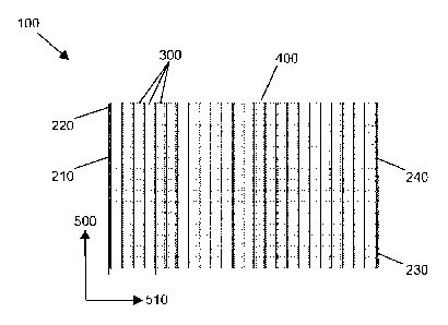
[0006] FIG. 1 is a top view of the fabric of the present invention..
[0007] FIG. 2 is a close-up view of the reinforcement system of the present
invention.
[0008] FIG. 3 is a close-up view of the reinforcement system of the present
invention.
[0009] FIG. 4 is a cross-sectional view of the reinforcement system of the
present
invention.
[0010] FIG. 5 is a close-up view of the reinforcement system of the present
invention.
[0011] FIG. 6 is a perspective view of the fabric of the present invention.
[0012] FIG. 7 is a close-up view of the reinforcement system of the present
invention.
[0013] FIG. 8 is a perspective cross-sectional view of the reinforcement
system of
the present invention.
[0014] FIG. 9 is a perspective cross-sectional view of the reinforcement
system of
the present invention.
[0015] FIG. 10 is a view of the structural repair and reinforcement system of
the
present invention.
[0016] FIG. 11A-11C is a perspective view of embodiments of the housing
matrix.
[0017] FIG. 12A-12M is a perspective view of embodiments of the channel.
DESCRIPTION OF PREFERRED EMBODIMENTS
[0018] Following is a list of elements corresponding to a particular element
referred
to herein:
[0019] 100 Reinforcement fabric
[0020] 210 First fabrid edge seam
2
CA 02859771 2019-06-18
WO 2012/088354
PCT/US2011/066654
[0021] 220 First fabric edge
[0022] 230 Second fabric edge seam
[0023] 240 Second fabric edge
[0024] 300 Pocket
[0025] 310 First pocket seam
[0026] 320 First pocket edge
[0027] 330 Second pocket seam
[0028] 340 Second pocket edge
[0029] 350 Pocket front surface
[0030] 360 Pocket rear surface
[0031] 370 Stitching
[0032] 380 Pocket cross-stitch
[0033] 382 Stitch first end
=
[0034] 384 Stitch second end
[0035] 400 Fiber tow
[0036] 410 Filament
[0037] 420 Stack
[0038] 500 X-axis (0 degrees)
[0039] 510 Y-axis or 90 degrees
[0040] 520 Z-axis
[0041] 600 Polymer resin composition
[0042] 6.10 Resin component
[0043] 620 Activation component
[0044] 630 Modified vinyl ester resin composition
[0045] 700 Substrate
[0046] 710 Low-viscosity epoxy primer
[0047] 720 Roller
[0048] 730 Packaging
[0049] 740 Open area
[0050] 800 Structural repair and reinforcement system
[0051] 810 Preimpregnated structural repair and reinforcement system
[0052] 820 Reinforcement system
[0053] 900 Reinforcement fiber housing matrix
3
CA 02859771 2014-06-18
WO 2012/088354 PCT/US2011/066654
[0054] 910 Channel
[0055] 920 First channel side
[0056] 930 Second channel side
[0057] 950 Sub-channel
[0058] NOVEL REINFORCEMENT SYSTEM
[0059] Referring now to FIG. 1-12M, the present invention features a novel
reinforcement fabric (100) system for maximizing tensile strength and modulus
of
elasticity per ply for composite systems. In some embodiments, this is
measured in
pounds / inch / width.
[0060] In some embodiments, the fabric (100) has a first fabric edge seam
(210)
located on a first fabric edge (220), and a second fabric edge seam (230)
located on
a second fabric edge (240). In some embodiments, the first fabric edge seam
(210)
traverses and binds the fabric (100) parallel and adjacent to the first fabric
edge
(220), and the second fabric edge seam (230) traverses and binds the fabric
(100)
parallel to and adjacent to the second fabric edge (240). In some embodiments,
the
first fabric edge (220) and second fabric edge (240) traverse the fabric (100)
in the
direction of an X-axis (0 degrees) (500).
[0061] In some embodiments, the fabric (100) has a pocket (300) with a first
pocket
edge (320), a second pocket edge (340), a pocket front surface (350), and a
pocket
rear surface (360). In some embodiments, the pocket (300) has a first pocket
seam
(310) located on the first pocket edge (320). In some embodiments, the first
pocket
seam (310) has a stitching (370) in a plane defined by the X-axis (0 degrees)
(500)
and a Z-axis (520) alternatingly attaching the pocket front surface (350) to
the pocket
rear surface (360) via the stitching (370). In some embodiments, the first
pocket
seam (310) traverses the fabric (100) parallel and adjacent to the first
pocket edge
(320).
[0062] In some embodiments, the pocket (300) has a second pocket seam (330)
located on the second pocket edge (340). In some embodiments, the second
pocket
seam (330) has a stitching (370) in a plane defined by the X-axis (0 degrees)
(500)
4
CA 02859771 2019-06-18
WO 2012/088354 PCT/US2011/066654
and the Z-axis (520) alternatingly attaching the pocket front surface (350) to
the
pocket rear surface (360) via the stitching (370). In some embodiments, the
second
pocket seam (330) traverses the fabric (100) parallel and adjacent to the
second
pocket edge (340).
[0063] In some embodiments, the pocket front surface (350) has a pocket cross-
stitch (380) that perpendicularly traverses the pocket (300) with respect to
the first
pocket seam (310) and the second pocket seam (330) in a direction of a Y-axis
or 90
degrees (510). In some embodiments, the pocket rear surface (360) has a pocket
cross-stitch (380) that perpendicularly traverses the pocket (300) with
respect to the
first pocket seam (310) and the second pocket seam (330) in the direction of
the Y-
axis or 90 degrees (510).
[0064] In some embodiments, the pocket cross-stitch (380) has a stitch first
end
(382) attached to the first pocket seam (310) and a stitch second end (384)
attached
to the second pocket seam (330).
[0065] In some embodiments, the pocket (300) traverses the fabric (100)
parallel
and adjacent to the first fabric edge (220) and the second fabric edge (240)
in a
warp, or 0 degree, or X-axis (500) direction.
[0066] In some embodiments, the fabric (100) has a fiber tow (400) with a
plurality
of filaments (410) located in a stack (420). In some embodiments, the fiber
tow
(400) is located lengthways in the direction of the X-axis (0 degrees) (500)
in the
pocket (300).
[0067] In some embodiments, the filament (410) is constructed from a material
selected from a group consisting of: polyethylene, glass, basalt, aramid, and
carbon.
[0068] In some embodiments, a plurality of pockets (300) is located in
parallel in a
series. In some embodiments, a first pocket edge (320) of a first pocket (300)
is
joined to a second pocket edge (340) of a second pocket (300). In some
embodiments, a plurality of pockets (300) is joined in parallel in a series at
the first
pocket edge (320) and the second pocket edge (340) of each pocket (300) in the
CA 02859771 2019-06-18
WO 2012/088354
PCT/US2011/066654
series.
[0069] In some embodiments, the pocket (300) is located in a weft, or 90
degree, or
Y-axis (510) direction with respect to the first fabric edge (220) and the
second fabric
edge (240).
[0070] In some embodiments, the fiber tow (400) has from about 1 filament
(410) to
about 3,000 filaments (410). In some embodiments, the fiber tow (400) has from
about 3,000 filaments (410) to about 6,000 filaments (410). In some
embodiments,
the fiber tow (400) has from about 6,000 filaments (410) to about 12,000
filaments
(410). In some embodiments, the fiber tow (400) has from about 12,000
filaments
(410) to about 50,000 filaments (410). In some embodiments, the fiber tow
(400)
has more than about 50,000 filaments (410). In some embodiments, the fiber tow
(400) has more than about 400,000 filaments (410).
[0071] In some embodiments, the cross-sectional area of the stacks (420) is
about
50% to 70% of the cross-sectional area of the pocket (300). In some
embodiments,
the cross-sectional area of the stacks (420) is about 70% to 85% of the cross-
sectional area of the pocket (300). In some embodiments, the cross-sectional
area
of the stacks (420) is about 85% to 99.5% of the cross-sectional area of the
pocket
(300).
[0072] In some embodiments, the volume of the stacks (420) in the pocket (300)
is
about 50% to 70% of the volume of the pocket (300). In some embodiments, the
volume of the stacks (420) in the pocket (300) is about 70% to 85% of the
volume of
the pocket (300). In some embodiments, the volume of the stacks (420) in the
pocket (300) is about 85% to 99.5% of the volume of the pocket (300).
[0073]
[0074] In some embodiments, the fiber tow (400) has a plurality of non-
interlaced
filaments (410). In some embodiments, the fiber tow (400) has a plurality of
interlaced filaments (410). In some embodiments, the fiber tow (400) has a
plurality
of non-twisted filaments (410). In some embodiments, the fiber tow (400) has a
6
CA 02359771 2014-06-18
WO 2012/088354
PCT/US2011/066654
plurality of twisted filaments (410).
[0075] In some embodiments, the fiber tow (400) has a plurality of filaments
(410)
located one upon another forming a generally elliptical cross-section of the
fiber tow
(400) located in the pocket (300).
[0076] In some embodiments, the pocket front surface (350) has an open area
(740) greater than 50%. In some embodiments, the open area (740) has an area
wherein filaments (410) are exposed between a plurality of pocket cross-
stitches
(380) of the pocket front surface (350).
[0077] In some embodiments, the pocket rear surface (360) has an open area
(740)
greater than 50%. In some embodiments, the open area (740) has an area wherein
filaments (410) are exposed between a plurality of pocket cross-stitches (380)
of the
pocket rear surface (360).
[0078] In some embodiments, the fabric (100) is electrically conductive. In
some
embodiments, the fabric (100) contains a heating element. In some embodiments,
the fabric (100) contains a resistance wire, ribbon, or strip. In some
embodiments,
the fabric (100) is attached to a regulated power supply. In some embodiments,
the
fabric (100) is operatively attached to a regulated power supply to power the
heating
element of the fabric (100) to a controlled temperature using Joule heating.
In some
embodiments, the heated fabric (100) can be used to activate a modified vinyl
ester
resin composition (630). In some embodiments, the heated fabric (100) can be
used
to activate a resin composition.
[0079] In some embodiments, the thread used for the first fabric edge seam
(210),
second fabric edge seam (230), first pocket seam (310), second pocket seam
(330),
stitching (370), and pocket cross-stitch (380) are manufactured from a
polyester.
[0080] In some embodiments, Low-viscosity epoxy primer (710) measures between
about 200 and 800 centipoise (cP).
CA 02859771 2014-06-18
WO 2012/088354 PCT/US2011/066654
[0081] In some embodiments, the roller (720) is a nap roller (720).
[00132] In some embodiments, air-tight packaging (730) includes vacuum sealed
packaging (730).
[0083] STRUCTURAL REPAIR AND REINFORCEMENT SYSTEM
[0084] In some embodiments, a structural repair and reinforcement system (800)
for
maximizing tensile strength and modulus of elasticity per ply via composite
technology has a ply of reinforcement fabric (100). In some embodiments, the
fabric
(100) has a first fabric edge seam (210) located on a first fabric edge (220),
and a
second fabric edge seam (230) located on a second fabric edge (240). In some
embodiments, the first fabric edge seam (210) traverses and binds the fabric
(100)
parallel and adjacent to the first fabric edge (220), and the second fabric
edge seam
(230) traverses and binds the fabric (100) parallel to and adjacent to the
second
fabric edge (240). In some embodiments, the first fabric edge (220) and second
fabric edge (240) traverse the fabric (100) in the direction of an X-axis (0
degrees)
(500).
[0085] In some embodiments, the fabric (100) has a pocket (300) with a first
pocket
edge (320), a second pocket edge (340), a pocket front surface (350), and a
pocket
rear surface (360). In some embodiments, the pocket (300) has a first pocket
seam
(310) located on the first pocket edge (320). In some embodiments, the first
pocket
seam (310) has a stitching (370) in a plane defined by the X-axis (0 degrees)
(500)
and a Z-axis (520) alternatingly attaching the pocket front surface (350) to
the pocket
rear surface (360) via the stitching (370). In some embodiments, the first
pocket
seam (310) traverses the fabric (100) parallel and adjacent to the first
pocket edge
(320).
[0086] In some embodiments, the pocket (300) has a second pocket seam (330)
located on the second pocket edge (340). In some embodiments, the second
pocket
seam (330) has a stitching (370) in a plane defined by the X-axis (0 degrees)
(500)
and the Z-axis (520) alternatingly attaching the pocket front surface (350) to
the
pocket rear surface (360) via the stitching (370). In some embodiments, the
second
CA 02859771 2019-06-18
WO 2012/088354
PCT/US2011/066654
pocket seam (330) traverses the fabric (100) parallel and adjacent to the
second
pocket edge (340).
[0087] In some embodiments, the pocket front surface (350) has a pocket cross-
stitch (380) that perpendicularly traverses. the pocket (300) with respect to
the first
pocket seam (310) and the second pocket seam (330) in a direction of a Y-axis
or 90
degrees (510). In some embodiments, the pocket rear surface (360) has a pocket
cross-stitch (380) that perpendicularly traverses the pocket (300) with
respect to the
first pocket seam (310) and the second pocket seam (330) in the direction of
the Y-
axis or 90 degrees (510).
[0088] In some embodiments, the pocket cross-stitch (380) has a stitch first
end
(382) attached to the first pocket seam (310) and a stitch second end (384)
attached
to the second pocket seam (330).
[0089] In some embodiments, the pocket (300) traverses the fabric (100)
parallel
and adjacent to the first fabric edge (220) and the second fabric edge (240)
in a
warp, or 0 degree, or X-axis (500) direction.
[0090] In some embodiments, the pocket (300) has a fiber tow (400) with a
plurality
of filaments (410) located in a stack (420). In some embodiments, the fiber
tow
(400) is located lengthways in the direction of the X-axis (0 degrees) (500)
in the
pocket (300).
[0091] In some embodiments, the filament (410) is constructed from a material
selected from a group consisting of: polyethylene, glass, basalt, aramid, and
carbon.
[0092] In some embodiments, a plurality of pockets (300) is located in
parallel in a
series. In some embodiments, a first pocket edge (320) of a first pocket (300)
is
joined to a second pocket edge (340) of a second pocket (300). In some
embodiments, a plurality of pockets (300) is joined in parallel in a series at
the first
pocket edge (320) and the second pocket edge (340) of each pocket (300) in the
series.
9
CA 02859771 2019-06-18
WO 2012/088354 PCT/US2011/066654
[0093] In some embodiments, a structural repair and reinforcement system (800)
for
maximizing tensile strength and modulus of elasticity per ply via composite
technology has a polymer resin composition (600). In some embodiments, the
polymer resin composition (600) has a resin component (610) and an activation
component (620).
[0094] In some embodiments, the structural repair and reinforcement system
(800)
is stored until installed by an end user.
[0095] STRUCTURAL REPAIR AND REINFORCEMENT SYSTEM VIA
PREIMPREGNATED COMPOSITE TECHNOLOGY
[0096] In some embodiments, A preimpregnated structural repair and
reinforcement
system (810) for maximizing tensile strength and modulus of elasticity per ply
via
preimpregnated composite technology has a ply of reinforcement fabric (100).
In
some embodiments, the fabric (100) has a first fabric edge seam (210) located
on a
first fabric edge (220), and a second fabric edge seam (230) located on a
second
fabric edge (240). In some embodiments, the first fabric edge seam (210)
traverses
and binds the fabric (100) parallel and adjacent to the first fabric edge
(220), and the
second fabric edge seam (230) traverses and binds the fabric (100) parallel to
and
adjacent to the second fabric edge (240). In some embodiments, the first
fabric
edge (220) and second fabric edge (240) traverse the fabric (100) in the
direction of
an X-axis (0 degrees) (500).
[0097] In some embodiments, the reinforcement fabric (100) has a pocket (300)
with a first pocket edge (320), a second pocket edge (340), a pocket front
surface
(350), and a pocket rear surface (360). In some embodiments, the pocket (300)
has
a first pocket seam (310) located on the first pocket edge (320). In some
embodiments, the first pocket seam (310) has a stitching (370) in a plane
defined by
the X-axis (0 degrees) (500) and a Z-axis (520) alternatingly attaching the
pocket
front surface (350) to the pocket rear surface (360) via the stitching (370).
In some
embodiments, the first pocket seam (310) traverses the fabric (100) parallel
and
adjacent to the first pocket edge (320).
CA 02859771 2019-06-18
WO 2012/088354
PCT/US2011/066654
[0098] In some embodiments, the pocket (300) has a second pocket seam (330)
located on the second pocket edge (340). In some embodiments, the second
pocket
seam (330) has a stitching (370) in a plane defined by the X-axis (0 degrees)
(500)
and the Z-axis (520) alternatingly attaching the pocket front surface (350) to
the
pocket rear surface (360) via the stitching (370). In some embodiments, the
second
pocket seam (330) traverses the fabric (100) parallel and adjacent to the
second
pocket edge (340).
[0099] In some embodiments, the pocket front surface (350) has a pocket cross-
stitch (380) that perpendicularly traverses the pocket (300) with respect to
the first
pocket seam (310) and the second pocket seam (330) in a direction of a Y-axis
or 90
degrees (510). In some embodiments, the pocket rear surface (360) has pocket
cross-stitch (380) that perpendicularly traverses the pocket (300) with
respect to the
first pocket seam (310) and the second pocket seam (330) in the direction of
the Y-
axis or 90 degrees (510).
[00100] In some embodiments, the pocket cross-stitch (380) has a stitch first
end
(382) attached to the first pocket seam (310) and a stitch second end (384)
attached
to the second pocket seam (330).
[00101]In some embodiments, the pocket (300) traverses the fabric (100)
parallel
and adjacent to the first fabric edge (220) and the second fabric edge (240)
in a
warp, or 0 degree, or X-axis (500) direction.
[00102] In some embodiments, the pocket has a fiber tow (400) with a plurality
of
filaments (410) located in a stack (420). In some embodiments, the fiber tow
(400) is
located lengthways in the direction of the X-axis (0 degrees) (500) in the
pocket
(300).
[00103] In some embodiments, the filament (410) is constructed from a material
selected from a group consisting of: polyethylene, glass, basalt, aramid, and
carbon.
[00104] In some embodiments, a preimpregnated structural repair and
reinforcement
system (810) for maximizing tensile strength and modulus of elasticity per ply
via
11
CA 02859771 2014-06-18
WO 2012/088354
PCT/US2011/066654
preimpregnated composite technology has a modified vinyl ester resin
composition
.(630) located (or preimpregnated) on the reinforcement fabric (100).
In some embodiments, the modified vinyl ester resin composition (630) is "
cross-linked with a peroxide radical cure.ln some embodiments, a modified
vinyl ester
resin composition is available as DION 35051-00 as of December 21, 2011.
[00105]In some embodiments, the system (810) is stored until installed by an
end
user. In some embodiments, the system (810) has a shelf life of six months. In
some embodiments, the system (810) can be stored in an environment having
temperatures about ambient. In some embodiments, ambient temperature is less
than about 60 degrees Fahrenheit. In some embodiments ambient temperature is
about 60 degrees Fahrenheit to about 80 degrees Fahrenheit. In some
embodiments, ambient temperature is about 80 degrees Fahrenheit to about 100
degrees Fahrenheit. In some embodiments, ambient temperature is greater than
100 degrees Fahrenheit. In some embodiments, the system (810) has air-tight
packaging (730).
=
[00106]In some embodiments, the system (810) is activated for curing upon
raising
the temperature of the system (810) to about 275 degrees Fahrenheit for about
15
minutes. In some embodiments, the system (810) is activated for curing via
exposure to water.
[00107]STRUCTURAL REPAIR AND REINFORCEMENT METHOD
[00108]In some embodiments, a method for maximizing tensile strength and
modulus of elasticity per ply in a reinforcement or repair operation via
composite
technology includes obtaining a structural repair and reinforcement system
(800).
[00109]In some embodiments, the system (800) has a ply of reinforcement fabric
(100) having a first fabric edge seam (210) located on a first fabric edge
(220), and a
second fabric edge seam (230) located on a second fabric edge (240). In some =
12
CA 02859771 2014-06-18
WO 2012/088354 PCT/US2011/066654
embodiments, the first fabric edge seam (210) traverses and binds the fabric
(100)
parallel and adjacent to the first fabric edge (220), and the second fabric
edge seam
(230) traverses and binds the fabric (100) parallel to and adjacent to the
second
fabric edge (240). In some embodiments, the first fabric edge (220) and second
fabric edge (240) traverse the fabric (100) in the direction of an X-axis (0
degrees)
(500).
[00110]In some embodiments, the fabric (100) has a pocket (300) with a first
pocket
edge (320), a second pocket edge (340), a pocket front surface (350), and a
pocket
rear surface (360). In some embodiments, the pocket (300) has a first pocket
seam
(310) located on the first pocket edge (320). In some embodiments, the first
pocket
seam (310) has a stitching (370) in a plane defined by the X-axis (0 degrees)
(500)
and a Z-axis (520) alternatingly attaching the pocket front surface (350) to
the pocket
rear surface (360) via the stitching (370). In some embodiments, the first
pocket
seam (310) traverses the fabric (100) parallel and adjacent to the first
pocket edge
(320).
[00111]In some embodiments, the pocket (300) has a second pocket seam (330)
located on the second pocket edge (340). In some embodiments, the second
pocket
seam (330) having a stitching (370) in a plane defined by the X-axis (0
degrees)
(500) and the Z-axis (520) alternatingly attaching the pocket front surface
(350) to
the pocket rear surface (360) via the stitching (370). In some embodiments,
the
second pocket seam (330) traverses the fabric (100) parallel and adjacent td
the
second pocket edge (340).
[00112]In some embodiments, the pocket front surface (350) has pocket cross-
stitch
(380) that perpendicularly traverses the pocket (300) with respect to the
first pocket
seam (310) and the second pocket seam (330) in a direction of a Y-axis or 90
degrees (510). In some embodiments, the pocket rear surface (360) has a pocket
cross-stitch (380) that perpendicularly traverses the pocket (300) with
respect to the
first pocket seam (310) and the second pocket seam (330) in the direction of
the Y-
axis or 90 degrees (510).
13
CA 02859771 2014-06-18
WO 2012/088354
PCT/US2011/066654
[00113]In some embodiments, the pocket cross-stitch (380) has a stitch first
end
(382) attached to the first pocket seam (310) and a stitch second end (384)
attached
to the second pocket seam (330).
[00114]In some embodiments, the pocket (300) traverses the fabric (100)
parallel
and adjacent to the first fabric edge (220) and the second fabric edge (240)
in a
warp, or 0 degree, or X-axis (500) direction.
[00115] In some embodiments, the fabric (100) has a fiber tow (400) with a
plurality
of filaments (410) located in a stack (420). In some embodiments, the fiber
tow
(400) is located lengthways in the direction of the X-axis (0 degrees) (500)
in the
pocket (300).
[00116] In some embodiments, the filament (410) is constructed from a material
selected from a group consisting of: polyethylene, glass, basalt, aramid, and
carbon.
[00117] In some embodiments, a plurality of pockets (300) is located in
parallel in a
series. In some embodiments, a first pocket edge (320) of a first pocket (300)
is
joined to a second pocket edge (340) of a second pocket (300). In some
embodiments, a plurality of pockets (300) is joined in parallel in a series at
the first
pocket edge (320) and the second pocket edge (340) of each pocket (300) in the
series.
[00118] In some embodiments, the system (800) has a polymer resin composition
(600) with a resin component (610) and an activation component (620).
[00119] In some embodiments, the structural repair and reinforcement system
(800)
is stored until installed by an end user.
[00120] In some embodiments, a method for maximizing tensile strength and
= modulus of elasticity per ply in a reinforcement or repair operation via
composite
technology includes preparing a substrate (700) for application via cleaning
the
substrate (700). In some embodiments, loose particles, scale, surface
oxidation,
14
CA 02859771 2014-06-18
WO 2012/088354 PCT/US2011/066654
and oily films are removed via physical abrasion or power washing.
[00121]In some embodiments, a method for maximizing tensile strength and
modulus of elasticity per ply in a reinforcement or repair operation via
composite
technology includes preparing a substrate (700) for application via priming
the
substrate (700) with a low-viscosity epoxy primer (710). In some embodiments,
the
primer (710) is applied to the substrate (700) via a roller (720).
[00122]In some embodiments, a method for maximizing tensile strength and
modulus of elasticity per ply in a reinforcement or repair operation via
composite
technology includes preparing the polymer resin composition (600) for
application via
combining the resin component (610) and the activation component (620) in a
specified ratio.
[00123]WET LAYUP OPTION
[00124]In some embodiments, a wet layup method for maximizing tensile strength
and modulus of elasticity per ply in a reinforcement or repair operation via
composite
technology includes preparing a substrate (700) for application via applying a
tack
coat, or a thickened paste. In some embodiments, the tack coat consists of the
polymer resin composition (600). In some embodiments, the tack coat is applied
to
the substrate (700) via the roller (720). In some embodiments, a method for
maximizing tensile strength and modulus of elasticity per ply in a
reinforcement or
repair operation via composite technology includes applying a saturating
quantity of
the resin composition (600) to the surface of the reinforcement fabric (100).
In some
embodiments, the resin composition (600) is applied to the substrate (700) via
the
roller (720). In some embodiments, the resin composition (600) is applied to
the
reinforcement fabric (100) via a saturation machine. In some embodiments, a
method for maximizing tensile strength and modulus of elasticity per ply in a
=
reinforcement or repair operation via composite technology includes laying a
ply of
reinforcement fabric (100) on the prepared substrate (700). In some
embodiments,
the ply of reinforcement fabric (100) is laid in a direction wherein the
pocket (300)
direction linearly traverses the hoop direction of a pipe or other substrate.
CA 02859771 2014-06-18
WO 2012/088354
PCT/US2011/066654
[00125]DRY LAYUP OPTION
[00126]In some embodiments, a dry layup method for maximizing tensile strength
and modulus of elasticity per ply in a reinforcement or repair operation via
composite
technology includes laying a ply of reinforcement fabric (100) on the prepared
substrate (700). In some embodiments, the ply of reinforcement fabric (100) is
laid
in a direction wherein the pocket (300) direction linearly traverses the hoop
direction
of a pipe or other substrate.
=
[00127]In some embodiments, a method for maximizing tensile strength and
modulus of elasticity per ply in a reinforcement or repair operation via
composite
technology includes distributing the resin composition (600) through an open
area
(740) of the reinforcement fabric (100) until the reinforcement fabric (100)
is
saturated by the resin composition (600). In some embodiments, the resin
composition (600) is distributed through the open area (740) of the
reinforcement
fabric (100) via the roller (720).
[00128]In some embodiments, a method for maximizing tensile strength and
modulus of elasticity per ply in a reinforcement or repair operation via
composite
technology includes repeating the process of laying the fabric (100), applying
the
resin composition (600), and distributing the resin composition (600) until a
desired
thickness of the structural repair and reinforcement system (800) is reached.
In
some embodiments, one or more plys of reinforcement fabric (100) can be laid
on a
prepared substrate (700). In some embodiments, a ply is a single layer of the
reinforcement fabric (100).
[00129]In some embodiments, a method for maximizing tensile strength and
modulus of elasticity per ply in a reinforcement or repair operation via
composite
technology includes applying a finish coat of resin composition (600) to an
exterior
surface of the laid fabric (100). In some embodiments, the finish coat is
applied to
the exterior surface of the laid fabric (100) via the roller (720).
16
CA 02859771 2019-06-18
WO 2012/088354
PCT/US2011/066654
[001 30]STRUCTURAL REPAIR AND REINFORCEMENT METHOD VIA
PREIMPREGNATED COMPOSITE TECHNOLOGY
[00131] In some embodiments, a method for maximizing tensile strength and
modulus of elasticity per ply in a reinforcement or repair operation via
preimpregnated composite technology includes obtaining a structural repair and
reinforcement system (810).
[00132]In some embodiments, the system (810) has a ply of reinforcement fabric
(100) having a first fabric edge seam (210) located on a first fabric edge
(220), and a
second fabric edge seam (230) located on a second fabric edge (240). In some
embodiments, the first fabric edge seam (210) traverses and binds the fabric
(100)
parallel and adjacent to the first fabric edge (220), and the second fabric
edge seam
(230) traverses and binds the fabric (100) parallel to and adjacent to the
second
fabric edge (240). In some embodiments, the first fabric edge (220) and second
fabric edge (240) traverse the fabric (100) in the direction of an X-axis (0
degrees)
(500).
[00133] In some embodiments, the fabric (100) has a pocket (300) with a first
pocket
edge (320), a second pocket edge (340), a pocket front surface (350), and a
pocket
rear surface (360). In some embodiments, the pocket (300) has a first pocket
seam
(310) located on the first pocket edge (320). In some embodiments, the first
pocket
seam (310) has a stitching (370) in a plane defined by the X-axis (0 degrees)
(500)
and a Z-axis (520) alternatingly attaching the pocket front surface (350) to
the pocket
rear surface (360) via the stitching (370). In some embodiments, the first
pocket
seam (310) traverses the fabric (100) parallel and adjacent to the first
pocket edge
(320).
[00134]In some embodiments, the pocket (300) has a second pocket seam (330)
located on the second pocket edge (340). In some embodiments, the second
pocket
seam (330) has a stitching (370) in a plane defined by the X-axis (0 degrees)
(500)
and the Z-axis (520) alternatingly attaching the pocket front surface (350) to
the
pocket rear surface (360) via the stitching (370). In some embodiments, the
second
17
CA 02859771 2014-06-18
WO 2012/088354
PCT/US2011/066654
pocket seam (330) traverses the fabric (100) parallel and adjacent to the
second
pocket edge (340).
[00135] In some embodiments, the pocket front surface (350) has a pocket cross-
stitch (380) that perpendicularly traverses the pocket. (300) with respect to
the' first
pocket seam (310) and the second pocket seam (330) in a direction of a Y-axis
or 90
degrees (510). In some embodiments, the pocket rear surface (360) has a pocket
cross-stitch (380) that perpendicularly traverses the pocket (300) with
respect to the
first pocket seam (310) and the second pocket seam (330) in the direction of
the Y-
axis or 90 degrees (510).
[00136]!n some embodiments, the pocket cross-stitch (380) has a stitch first
end
(382) attached to the first pocket seam (310) and a stitch second end (384)
attached
to the second pocket seam (330).
[00137] In some embodiments, the pocket (300) traverses the fabric (100)
parallel
and adjacent to the first fabric edge (220) and the second fabric edge (240)
in a
warp, or 0 degree, or X-axis (500) direction.
[00138] In some embodiments, the fabric (100) has a fiber tow (400) with a
plurality
of filaments (410) located in a stack (420). In some embodiments, the fiber
tow
(400) is located lengthways in the direction of the X-axis (0 degrees) (500)
in the
pocket (300).
[00139] In some embodiments, the filament (410) is constructed from a material
selected from a group consisting of: polyethylene, glass, basalt, aramid, and
carbon.
[00140] In some embodiments, a modified vinyl ester resin composition (630) is
located on the reinforcement fabric (100).
In some embodiments,
the modified vinyl ester resin composition (630) is cross-linked with a
peroxide radical
cure. In some embodiments, a modified vinyl ester resin composition is
available as DION 35051-00 as of December 21, 2011.
18
CA 02859771 2014-06-18
WO 2012/088354
PCT/US2011/066654
[00141] In some embodiments, the system (810) is stored until installed by an
end
user. In some embodiments, the system (810) has a shelf life of six months. In
some embodiments, the system (810) can be stored in an environment having
temperatures about ambient. In some embodiments, ambient temperature is less
than about 60 degrees Fahrenheit. In some embodiments ambient temperature is
about 60 degrees Fahrenheit to about 80 degrees Fahrenheit. In some
embodiments, ambient temperature is about 8 In some embodiments, the system
(810) has air-tight packaging (730).
[00142] In some embodiments, the system (810) is heat-activated. In some
embodiments, the system (810) is activated for curing upon raising the
temperature
of the system (810) to about 275 degrees Fahrenheit for about 15 minutes. In
some
embodiments, the system (810) is activated upon exposure to water.
[00143] In some embodiments, a method for maximizing tensile strength and
modulus of elasticity per ply in a reinforcement or repair operation via
preimpregnated composite technology includes preparing a substrate (700) for
application via cleaning the substrate (700). In some embodiments, loose
particles,
scale, surface oxidation, and oily films are removed via physical abrasion or
power
washing.
[00144] In some embodiments, a method for maximizing tensile strength and
modulus of elasticity per ply in a reinforcement or repair operation via
preimpregnated composite technology includes preparing a substrate (700) for
application via priming the substrate (700) with a low-viscosity epoxy primer
(710).
In some embodiments, the primer is applied to the substrate (700) via a roller
(720).
[00145] In some embodiments, a method for maximizing tensile strength and
modulus of elasticity per ply in a reinforcement or repair operation via
preimpregnated composite technology includes opening the air-tight packaging
(730)
19
CA 02859771 2014-06-18
WO 2012/088354
PCT/US2011/066654
ancIT'e-rnoving the reinforcement fabric (100) for use.
[00146] In some embodiments, a method for maximizing tensile strength and
modulus of elasticity per ply in a reinforcement or repair operation via
preimpregnated composite technology includes laying a ply of reinforcement
fabric
(100) on the prepared substrate (700). In some embodiments, the ply of
reinforcement fabric (100) is laid in a direction wherein the pocket (300)
linearly
traverses the hoop direction of a pipe or other substrate.
[00147] In some embodiments, a method for maximizing tensile strength and
modulus of elasticity per ply in a reinforcement or repair operation via
preimpregnated composite technology includes compressing the reinforcement
fabric (100) until the reinforcement fabric (100) is saturated by the resin
composition
(630). In some embodiments, the resin composition (630) is distributed through
the
open area (740) of the reinforcement fabric (100) via the roller (720).
[00148] In some embodiments, a method for maximizing tensile strength and
modulus of elasticity per ply in a reinforcement or repair operation via
preimpregnated composite technology includes repeating the process of laying
the
fabric (100), and distributing the resin composition (630) until the desired
thickness
of the preimpregnated structural repair and reinforcement system (810) is
reached.
In some embodiments, one or more plys of reinforcement fabric (100) can be
laid on
a prepared substrate (700). In some embodiments, a ply is a single layer of
the
reinforcement fabric (100).
[00149] In some embodiments, a reinforcement fiber housing matrix (900) for
maximizing tensile strength and modulus of elasticity per ply for composite
systems,
the housing matrix (900) has a channel (910) with a first channel side (920),
and a
second channel side (930); and a fiber tow (400) with a plurality of filaments
(410)
located in a stack (420).
[00150] In some embodiments, the fiber tow (400) is located lengthways in the
direction of the X-axis (0 degrees) (500) in the channel (910). In some
CA 02859771 2019-06-18
WO 2012/088354 PCT/US2011/066654
embodiments, the channel (910) traverses the matrix parallel and adjacent to
the
first channel side (920) and the second channel side (930) in a warp, or 0
degree, or
X-axis direction.
[00151] In some embodiments, a plurality of channels (910) is located in
parallel in a
series, with the first channel side (920) of a first channel (910) joined to a
second
channel side (930) of a second channel (910). In some embodiments, a plurality
of
channels (910) is joined in parallel in a series at the first channel side
(920) and the
second channel side (930) of each channel (910) in the series.
[00152] In some embodiments, the channel (910) has a cross-sectional shape of
a
polygon, for example, a triangle, a square, a rectangle, a hexagon or an
octagon. In
some embodiments, the channel (910) has a cross-sectional shape of an ellipse
or a
circle.
[00153] In some embodiments, a sub-channel (950) is located within the
channel. In
some embodiments, the sub-channel (950) is supported within the channel (910)
via
a structure. In some embodiments, the sub-channel (950) is a partitioned area
of the
channel (910).
[00154] In some embodiments, the sub-channel (950) has a cross-sectional shape
of =
a polygon, for example, a triangle, a square, a rectangle, a hexagon or an
octagon.
In some embodiments, the sub-channel (950) has a cross-sectional shape of an
ellipse or a circle.
[00155] In some embodiments, a polymer resin composition (600) is located in
the
sub-channel (950). In some embodiments, a corrosion resistant polymer resin
composition (600) is located in the sub-channel (950). In some embodiments, a
corrosion resistant compound is located in the sub-channel (950). In some
embodiments, corrosion resistant filaments (410) are located in the sub-
channel
(950).
[00156] In some embodiments, a chemically resistant polymer resin composition
21
CA 02859771 2014-06-18
WO 2012/088354
PCT/US2011/066654
(600) is located in the sub-channel (950). In some embodiments, a chemically
resistant compound is located in the sub-channel (950). In some embodiments,
chemically resistant filaments (410) are located in the sub-channel (950).
[00157]In some embodiments, a polymer resin composition (600) is located in
the
sub-channel (950), wherein the stack (420) is located in the channel (910). In
some
embodiments, a polymer resin composition (600) is located, alternatingly in
the sub-
channel (950) and the channel (910). In some embodiments, the stack (420) is
located altematingly in the sub-channel (950) and the channel (910).
[00158] In some embodiments, the channel (910) is constructed from a permeable
material. In some embodiments, the channel (910) is constructed from a mesh
material. In some embodiments, the channel (910) is constructed from a porous
material. In some embodiments, the channel (910) is constructed from a metal,
for
example, aluminum or steel.
[00159] In some embodiments, the sub-channel (950) is constructed from a
permeable material. In some embodiments, the sub-channel (950) is constructed
from a mesh material. In some embodiments, the sub-channel (950) is
constructed
=
from a porous material. In some embodiments, the sub-channel (950) is
constructed
from a metal, for example, aluminum or steel.
[00160] In some embodiments, the channel (910) is located in a weft, or 90
degree,
or Y-axis (510), direction with respect to the first channel side (920) and
the second
channel side (930).
=
[0016111n some embodiments, the fabric (100) is unidirectional, meaning
greater
than about 90% of the filaments (410) are oriented in a common direction. In
some
embodiments, the fabric (100) is bi-directional, meaning about 50% of the
filaments
(410) are oriented in a first direction, with the other about 50% of the
filaments (410)
are oriented in a direction perpendicular to the first direction. In some
embodiments,
the fabric (100) is layered in the 3 dimensional or Z-axis direction. In some
embodiments, plys of the fabric (100) is rotationally oriented in 45 degree
22
WO 2012/088354
PCT/US2011/066654
increments.
[00162] In some embodiments, the cross-sectional area of the stacks (420) is
about
50% to 70% of the cross-sectional area of the channel (910). In some
embodiments,
the cross-sectional area of the stacks (420) is about 70% to 85% of the cross-
sectional area of the channel (910). In some embodiments, the cross-sectional
area
of the stacks (420) is about 85% to 99.5% of the cross-sectional area of the
channel
(910).
[00163] In some embodiments, the volume of the stacks (420) in the channel
(910) is
about 50% to 70% of the volume of the channel (910). In some embodiments, the
volume of the stacks (420) in the channel (910) is about 70% to 85% of the
volume
of the channel (910). In some embodiments, the volume of the stacks (420) in
the
channel (910) is about 85% to 99.5% of the volume of the channel (910).
[00164] As used herein, the term "about" refers to plus or minus 10% of the
referenced number. For example, an embodiment wherein there are about 3000
filaments (410) includes between 2700 and 3300 filaments (410).
[00165] Various modifications of the invention, in addition to those described
herein,
will be apparent to those skilled in the art from the foregoing description.
Such
modifications are also intended to fall within the scope of the appended
claims.
[00166] Although there has been shown and described the preferred embodiment
of
the present invention, it will be readily apparent to those skilled in the art
that
modifications may be made thereto which do not exceed the scope of the
appended
claims. Therefore, the scope of the invention is only to be limited by the
following
claims.
[00167] The reference numbers recited in the below claims are solely for ease
of
examination of this patent application, and are exemplary, and are not
intended in
23
CA 2 8597 71 2 0 1 8-0 1-30
CA 02859771 2019-06-18
WO 2012/088354
PCT/US2011/066654
any way to limit the scope of the claims to the particular features having the
corresponding reference numbers in the drawings.
24