Note : Les descriptions sont présentées dans la langue officielle dans laquelle elles ont été soumises.
CA 02861188 2014-07-14
WO 2013/089826
PCTIUS2012/046519
RADIO FREQUENCY ID TAG HAVING STRUCTURE FOR INLAY SPACING
FIELD OF THE INVENTION
The present invention relates to the field of radio frequency identification
(RFID)
security tags, and in particular toward minimizing the effects of tag housings
on the
performance of the RFD inlays contained therein.
BACKGROUND OF THE INVENTION
Wireless communication tags are often found in retail and/or warehouse
environments, among other environments. The wireless communication tags may be
used to
track and i.dentify items such as packages, containers, inventory items and
articles for
inventory, asset management and/or security purposes.
One type of wireless communication tag is a radio frequency identification
(RFID)
tag. The RFID tag transmits stored information, e.g., information relating to
an item using
.. radio frequency (RE) signals. In particular, the RFID tag may include an
inlay with an
antenna and integrated circuit (IC) chip disposed thereon in which the IC chip
is connected to
the antenna. The IC chip stores the programmed information, e.g., the
information relating to
the item. In response to receiving an interrogation signal from an RFID
reader, the IC chip
converts the programmed information into a corresponding electromagnetic
signal which is
transmitted by the antenna. The RFID tag is tuned to receive an interrogation
signal at a
particular frequency or narrow range of frequencies.
However, the performance of the RFID tag may vary depending on various
factors.
One factor involves the interaction between the inlay and the plastic housing
of the REID tag.
For example, when positioned outside and not in contact with the housing, the
antenna may
exhibit a specific response to the interrogation signal. Placing the substrate
with antenna
within the housing of the MD tag, may alter the frequency response of the
antenna such that
substantially less of the interrogation signal is captured by the RFID tag,
i.e., the RFID tag
CA 02861188 2014-07-14
WO 2013/089826
PCT/US2012/046519
may not "respond" or will respond poorly to the interrogation signal. The
interaction or
contact between the substrate and housing results in antenna detuning.
Moreover, movement
of the substrate within. the RFID tag may further vary the interaction between
the substrate
and housing such as to shift the tuned frequency of the antenna. For example,
the RFID tag
may be attached to an article that is moved around a store or warehouse such
that the
substrate with antenna is shifted around within the RFID tag which varies the
interaction
between the substrate and housing. An RFID tag that has becom.e detuned may be
unable to
receive the interrogation signal as the antenna is no longer tuned to the
interrogation signal.
In other words, an RFD reader is unable to read or interrogate the RFID tag,
or the reading
performance is degraded.
Another factor that affects performance of RFID tags is the housing material.
For
example, loss of signal or antenna detuning may be caused by the lossy
characteristics of the
plastic housing materials. Moreover, the variations in the housing materials
used by different
manufactures may also result in tuning variations. In other words, the housing
material itself
may detune the RFID tag.
Several solutions have been proposed to help maintain RFID tag performance.
One
solution is to inhibit movement of the substrate within the RFID tag. For
example, the
substrate may be glued to the housing or the housing may be constructed with a
clip-like
structure that firmly presses the substrate against the housing. While this
solution reduces
movement of the substrate, the interaction between the substrate and housing
is likely
increased. While the tuned frequency of the RFID tag may not vary due to
movement, the
increased interaction between substrate and housing may have detuned the
antenna, i.e., the
RFID tag will likely remain detuned.
Another solution involves reducing the interaction between the antenna and the
housing by increasing the housing size. In particular, the size of the housing
is increased
2
CA 02861188 2014-07-14
WO 2013/089826 PCT/US2012/046519
such that the antenna can be positioned away from the inlay support structure
of the housing.
However, this solution disadvantageously increases the size of tag such as to
increase cost of
manufacturing and detracts from. the aesthetic appeal of the item. to which
the tag is attached.
3
CA 02861188 2014-07-14
WO 2013/089826 PCT/US2012/046519
SUMMARY OF THE INVENTION
The present invention advantageously provides a system, device and method for
an
improved security tag housing.
According to one embodiment, a radio frequency identification, RFID, security
system tag is provided. The tag includes an RFID element and a first housing
portion. The
first housing portion defines an interior and an opening. The interior of the
first housing
portion includes an inner periphery and a shel.f disposed about at least a
portion of the inner
periphery. The interior of the first housing portion also includes a plurality
of protrusions in
which the plurality of protrusions extend outwardly from the shelf toward the
opening. The
RFID element is disposed at least in part on the plurality of protrusions.
According to another embodiment, a security system. tag is provided. The tag
includes a first housing portion that defines an interior and an opening. The
interior of the
first housing portion includes an inner periphery and a shelf disposed about
at least a portion
of the inner periphery. The interior of the first housing portion also
includes a plurality of
protrusions in which the plurality of protrusions extend outwardly from the
shelf toward the
opening.
According to another embodiment, a method is provided. A security tag is
attached to
an article. The security tag includes a radio frequency identification, REID,
element and a
housing portion. The housing portion defines an interior and an opening. The
interior of the
.. housing portion includes an inner periphery and a shelf disposed about at
least a portion of
the inner periphery. The interior of the housing portion includes a plurality
of protrusions in
which the plurality of protrusions extend outwardly from the shelf toward the
opening. The
RFID element is disposed at least in part on the plurality of protrusions.
4
81781241
According to one aspect of the present invention, there is provided a radio
frequency identification (RFID) security system tag, comprising: an RFID
element; and a first
housing portion, and a second housing portion, wherein the first housing
portion defining an
interior and an opening, wherein the interior of the first housing portion
including: an inner
periphery; a shelf disposed about at least a portion of the inner periphery;
and a plurality of
protrusions, the plurality of protrusions extending outwardly from the shelf
toward the
opening, the RFID element being disposed at least in part on the plurality of
protrusions such
that the interaction and/or physical contact between RFID element and shelf is
reduced.
4a
CA 2861188 2018-11-13
CA 02861188 2014-07-14
WO 2013/089826 PCT/US2012/046519
BRIEF DESCRIPTION OF THE DRAWINGS
A more complete understanding of the present invention, and the attendant
advantages
and features thereof, will be more readily understood by reference to the
following detailed
description when considered in conjunction with the accompanying drawings
wherein:
FIG. 1 illustrates a side view of an exemplary security tag system constructed
in
accordance with the present invention;
FM. 2 illustrates an. exploded view of the security tag system constructed in
accordance with the present invention;
FIG. 3 illustrates a perspective view of a first housing portion of the
security tag
constructed in accordance with the present invention;
FIG. 4 illustrates a top view of an. inlay constructed in accordance with the
present
invention;
FIG. 5 illustrates a perspective view of a second housing portion of the
security tag
constructed in accordance with the present invention;
FIG. 6 illustrates a perspective view of part of the security tag system
constructed in
accordance with the present invention;
FIG. 7 illustrates a cross-sectional view of part of the security tag system
constructed
in accordance with the present invention;
FIG. 8 illustrates another cross-sectional view of part of the security tag
system
constructed in accordance with the present invention;
FIG. 9 illustrates a cross-sectional view of part of another embodiment of the
security
tag system constructed in accordance with the present invention; and
FIG. 10 illustrates a side view of a protrusion constructed in accordance with
the
principles of the present invention;
5
CA 02861188 2014-07-14
WO 2013/089826 PCT/US2012/046519
FIG. 11 illustrates a side view of another protrusion constructed in
accordance with
the principles of the present invention;
FIG. 12 illustrates a side view of yet another protrusion constructed in
accordance
with the principles of the present invention;
FIG. 13 illustrates a side view of still yet another protrusion constructed in
accordance
with the principles of the present invention.
6
CA 02861188 2014-07-14
WO 2013/089826
PCT/US2012/046519
DETAILED DESCRIPTION OF THE INVENTION
The present invention advantageously provides a system, device and method for
radio
frequency identification. (RFID) tags. Accordingly, the system, device and
method
components have been represented where appropriate by conventional symbols in
the
drawings, showing only those specific details that are pertinent to
understanding the
embodiments of the present invention so as not to obscure the disclosure with
details that will
be readily apparent to those of ordinary skill in the art having the benefit
of the description
herein.
As used herein, relational twits, such as "first" and "second," "top" and
"bottom,"
and the like, may be used solely to distinguish one entity or element from
another entity or
element without necessarily requiring or implying any physical or logical
relationship or
order between such entities or elements.
Referring now to the drawing figures in which like reference designators refer
to like
elements there is shown in FIG. 1 a side view of an exemplary security tag
system
constructed in accordance with the principles of the present invention and
designated
generally as "10." System 10 includes a first housing portion 12 that may be
shaped to mate
with a tag detaching mechanism (not shown). First housing portion 12 may be
molded from
a polymer and/or another rigid material or materials. System 10 also includes
a second
housing portion 14 that may be shaped to mate with the detaching mechanism..
Second
housing portion 14 may be molded from a polymer and/or another rigid material
or materials.
For example, first housing portion 12 and/or second housing portion 14 may be
made from
hard plastic such as an injection molded Acrylonitrate-Butadiene-Styrene (ABS)
plastic or
other plastic such as a polycarbonate. First housing portion 12 and second
housing portion
14 are conjoining parts that may be affixed to each other via ultrasonic
welding and/or snap
7
CA 02861188 2014-07-14
WO 2013/089826
PCT/US2012/046519
fitting, among other joining mechanisms known in the art. When conjoined, the
first and
second portions may define a volume.
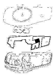
Referring to FIG. 2, an exploded view of system 10 is provided in accordance
with
the principles of the present invention. System 10 includes first housing
portion 12, second
housing portion 14, clamp 16 and/or inlay 18, among other components discussed
in detail
below. First housing portion 12 may include cavity 20 that may be shaped to
receive a
detachable security element, e.g., locking pin or tack (not shown). First
housing portion 12
may include aperture 22 that is configured to allow removable insertion of
detachable
security element into first housing portion 12. The detachable security
element may be a
locking pin or tack, among other detachable security elements that may be
removably
engaged with clamp 16.
Second housing portion 14 is discussed in detail below with reference to FIG.
5.
When conjoined or mated, the first and second portions define a volume. Clamp
16 is
configured to removably engage detachable security element. Clamp 16 is shaped
to mate
with second housing portion 14 and may be positioned within the interior or
inner area
defined by second housing portion 14, i.e., clamp 16 is disposed within the
volume defined
by the mated first and second portions. Clamp 16 may be made out metal and/or
plastic,
among other materials known in the art.
Inlay 18 is an insert that is configured to be disposed within the interior of
second
housing portion 14 or within the volume defined by the mated first and second
portions.
Inlay 18 may be an RFID inlay (also referred to as an "RFID element") as is
discussed in
detail with respect to FIG. 4. Inlay 18 may be shaped to fit within interior
or inner area of
second housing portion 14 as discussed in detail below with reference to FIG.
6. While
positioned within the interior of second housing portion 14, inlay 18 may be
substantially
secured in place by first housing portion 12 and/or second housing portion 14,
among other
8
CA 02861188 2014-07-14
WO 2013/089826
PCT/US2012/046519
elements. Inlay 18 may be rigid, semi-rigid or flexible based at least in part
on the materials
used to create inlay 18 and/or design need, among other factors. One of
ordinary skill in the
art will, recognize that other insert shapes and/or materials may be used
without detracting
from the spirit and scope of the invention.
An upper perspective view of first housing portion 12 of security system tag
10 is
described with reference to FIG. 3. First housing portion 12 includes interior
surface 23 and
interior area 24 in which interior area 24 is defined at least in part by the
periphery of first
housing portion .12. First housing portion 12 may include aperture 22
configured to allow a
detachable security element to be removably inserted therein. First housing
portion 12 may
include one or more constraining posts 26. Constraining posts 26 may be
configured to
constrain the movement of inlay 18 when inlay 18 is disposed within the
interior of second
housing portion 14, and when first housing portion 12 and second housing
portion 14 are
conjoined. In particular, constraining posts 26 may be configured to press at
least a portion
of inlay 18 against shelf 42 (FIG. 5), protrusion 44 (FIG. 5) and/or other
portions of second
.. housing portion 14 such that movement of inlay 18 in a direction
substantially perpendicular
to shelf 42 is reduced. Constraining post 26 may be configured not to
physically contact at
least antenna 30 (FIG. 5) and/or IC chip 34 (FIG. 5) when first housing
portion 12 is mated
with second housing portion 14 and when inlay 18 is disposed at least in part
on protrusion
44. While the shape of constraining posts 26 are shown as being substantially
cylindrical
and/or rectangular, other shapes may be incorporated based at least in part on
design need,
among other design considerations. First housing portion 12 may include
retainer 27 that is
configured to mate with mating element 50, discussed in detail with respect to
FIG. 5.
An electronic article surveillance (EAS) element 28 may be disposed within the
interior area
of first housing portion 12. In particular, EAS element may be sized to fit
within the interior
.. area of first housing portion 12. EAS element 28 may be removably affixed
to one or more
9
CA 02861188 2014-07-14
WO 2013/089826 PCT/US2012/046519
surfaces of first housing portion 12 via adhesive, among other methods known
in the art, e.g.,
EA.S element 28 may be removably affixed to interior surface 23. The EA.S
element 28 may
be an acoustomagnetic EA.S element, among other EAS elements known. in the
art.
A. top view of inlay 18 is described with reference to FIG. 4. Inlay 18 may be
an
RFID inlay that responds to an RFID interrogation signal. Inlay 18 includes
substrate 32 and
antenna 30 disposed on substrate 32. Antenna 30 is configured to receive and
transmit radio
frequency signals. In particular, antenna 30 has a pattern of conductive
material etched on. a
substrate 32. Antenna 30 may be positioned substantially along the periphery
of inlay 18.
Antenna 30 may be a dipole antenna or loop antenna, among other antennas known
in the art.
Inlay 18 may include integrated circuit ("IC") chip 34 disposed thereon and in
electrical
communication with antenna 30. IC chip 34 may store data associated with an.
item or article,
among other information. Inlay 18 may include one or more inlay apertures 36
that are
configured to mate with posts 46 on second housing portion 14, as described in
detail with
respect to FIG. 5. inlay 18 surface may include indentations (not shown)
configured to mate
with protrusion 44, thereby helping reduce movement of inlay 18.
Referring to FIG. 5, a perspective view of second housing portion 14 is
described.
Second housing portion 14 may include opening 40 and interior area 38 defined
at least in
part by the outer periphery of second housing portion 14. Second housing
portion 14 may
include shell...42 positioned along at least a portion of the periphery of
second housing portion
14. Shelf 42 may include at least first segment 42a, second segment(s) 42b and
third
segment(s) 42c in which second segment 42b and/or third segment 42c are
substantially
perpendicular to first segment 42a. First segment 42a and second segment 42b
may be
positioned along at least a portion of the periphery of second housing portion
14. Third
segment 42c may be positioned in between and substantially parallel to second
segment 42b.
First segment 42a, second segment 42b and third segment 42c may provide, at
least in part, a
CA 02861188 2014-07-14
WO 2013/089826
PCT/US2012/046519
support structure for inlay 18. First segment 42a, second segment 42b and
third segment 42c
may have respective lengths and widths in which the length of first segment
42a may be
greater than the length of second segment 42b and/or third segment 42c. One of
ordinary
skill in the art will understand that shelf 42 may be composed of one or more
segments.
Alternatively, the one or more segments may be separate or detached from shelf
42.
Second housing portion 14 may include one or more protrusions 44 disposed at
least
in part on a portion of shelf 42. A. protrusion 44 may extend outwardly from
shelf 42 towards
opening 40 such that protrusion 44 is substantially perpendicular to shelf 42.
Protrusion 44
may have a height defined by an amount protrusion 44 extends from shelf 42 as
discussed in
detail below with respect to FIGS. 8-9. While protrusion 44 is shown having a
cube-like or
rectangular prism-like shape, protrusion 44 may have other shapes such as a
cylindrical or
cone shape.
Protrusion 44 is configured to space inlay 18 from at least a portion of shelf
42 such
that the interaction andior physical contact between inlay 18 and shelf 42 is
reduced, i.e.,
antenna 30 is spaced apart from shelf 42. Protrusion 44 may be formed as part
of second
housing portion 14 or may be a separate element attached to shelf 42.
Protrusion 44 may be
disposed on shelf 42 in a periodic and/or non-periodic manner. In one
embodiment,
protrusion 44 is disposed along first segment 42a of shelf 42 while no
protrusions are
disposed along second segment 42b. The number of protrusions 44 disposed on
shelf 42 may
vary depending on design.
Second housing portion 14 may include one or more posts 46 configured to
engage
inlay 18. When engaged with inlay 18, post 46 may reduce movement of inlay 18
in a
direction substantially perpendicular to post 46 or parallel to shelf 42.
Second housing
portion 14 may include mating element 50 arranged to engage clamp 16 and
receptacle 27.
Second housing portion 14 may include receptacle 48 that is arranged to
receive the
11
CA 02861188 2014-07-14
WO 2013/089826 PCT/US2012/046519
detachable security element. Receptacle 48 may substantially align with
aperture 22. For
example, when first housing portion 12 and second housing portion 14 are
conjoined, the
detachable security element may be removably inserted through aperture 22 and
received by
receptacle 48 such that movement of detachable security element in a direction
perpendicular
receptacle 48 is reduced.
A perspective view of second housing portion 14 engaged with clamp 16 and
inlay 18
is described with reference to FIG. 6. Inlay 18 is positioned within the
interior of second
housing portion 14 such that inlay apertures 36 engage with posts 46. Inlay 18
is in contact
with shelf 42 and protrusion 44. In particular, protrusion 44 reduces the
interaction and/or
physical contact between inlay 18, i.e., antenna 30, and first segment 42a of
shelf 42 such that
the desired tuned frequency of inlay 18 is substantially maintained. For
example, reducing
the interaction between first segment 42a and inlay 18 may prevent the read
frequency of
inlay 18 from shifting by 15-20 MHz when contained by first and second housing
portions,
i.e., substantially maintains the read frequency of inlay 18. Alternatively,
the interaction
.. between first segment 42a and inlay 18 may substantially maintain the read
frequency of
inlay 18 between a first frequency such as 850 MHz and a second frequency such
as 950
MHz. Interaction and/or physical contact between inlay 18 and second segment
42h of shelf
42 may not substantially alter the tuned frequency of inlay 18 such that
protrusions are not
needed on second segment 42b and/or other segments of shelf. The outer
perimeter of the
shelf may substantially conform to an outer perimeter of the RFID inlay 18.
Clamp 16 is
engaged with mating element 50 and may be positioned such that at least a
portion of clamp
16 overlaps inlay 18.
Referring to FIG. 7, a cross-sectional view of a portion of second housing
portion 14
with inlay 18 disposed thereon is described. Protrusion 44 may space inlay 18
from shelf 42
such that the interaction between inlay 18 and shelf 42 is reduced, i.e., the
interaction
12
CA 02861188 2014-07-14
WO 2013/089826 PCT/US2012/046519
between antenna 30 and shelf 42 is reduced by spacing antenna 30 or inlay 18
apart from
shelf 42 via protrusion 44. While inlay 18 is shown as being substantially
planar, one of
ordinary skill in the art will recognize that inlay 18 may be composed of a
thin flexible
substrate that may not lay flat on one or more protrusions 44. The distance
between
protrusion 44 and the number of protrusions 44 may be varied based on design
need, among
other factors.
Referring to FIG. 8, a cross-sectional view of second housin.g portion 14 and
inlay 18
disposed thereon is illustrated. Shelf 42 has a height hl extending above a
bottom. surface of
second housing portion 14. Protrusions 44 have height h2 extending above the
shelf 42 such
that the height h2 of each protrusion is configured to substantially maintain
a predetermined
read frequency of RF1D inlay 18 when. RFID inlay 18 is disposed at least in
part on the
plurality of protrusions. Inlay 18 is disposed on shelf 42 and protrusions 44
such that the
physical and electrical interaction between inlay 18 and shelf 42 is reduced.
At least a
portion of antenna 30 may overlap, but be spaced away from, shelf 42.
Overlapping at least a
portion of antenna 30 and inlay 18 with shelf 42 allows the size of first and
second housing
portions to be kept to a minimum while still reducing the interaction between
shelf 42 and
inlay 18.
While at least a portion of antenna 30 is illustrated in FIG. 8 as being
offset from
protrusions 44, at least a portion of antenna 30 may alternatively be
configured to overlap at
least a portion of protrusions 44. Constraining post 26 may press inlay 18
against shelf 42
and protrusions 44 such as to reduce movement of inlay 18 in a direction
substantially
parallel to protrusions 44 and/or constraining post 26, or in a direction
substantially
perpendicular to shelf 42. For purposes of clarity, other portions of shelf
42, first housing
portion 12 and/or second housing portion 14 have been omitted from FIG. 8.
13
CA 02861188 2014-07-14
WO 2013/089826
PCT/US2012/046519
Referring to FIG. 9, a cross-sectional view of another embodiment including
second
housing portion 14 and inlay 18 disposed thereon is provided in accordance
with the
principles of the prevent invention. FIG. 9 substantially corresponds to
elements in FIG. 8
except that the height of shelf 42 on one side of second housing portion 14 is
lower than the
shelf height on a different side of second housing portion 14. For example,
one side of
second housing portion 14 such as segment 42h may have a shelf height of h3
while another
side such as segment 42a, e.g., distal side, may have a shelf height of hi.
Protrusions 44 are
disposed on shelf 42 having a height h2. The height of protrusion 44 may vary
such as
between 0.05 to 0.5 millimeter (mm), among other values based on design need.
One of
ordinary skill in the art will recognize that other height configurations may
be implemented
depending on manufacturing, cost considerations, overall size of system 10,
size of inlay 18
and/or positioning of other components within system 10, among other factors.
As with the embodiment of FIG. 8, the inlay 18 of FIG. 9 is configured such
that at
least a portion of antenna 30 is spaced from shelf 42 by protrusions 44. In
particular, at least
a portion of antenna 30 may overlap as least a portion of shelf 42 such as
first segment 42a.
While at least a portion of antenna 30 is illustrated in FIG. 9 as being
offset from protrusions
44, at least a portion of antenna 30 may alternatively be configured to
overlap, at least in part,
one of more protrusions 44.
Referring to FIG. 10, an exemplary side view of protrusion 44 is illustrated.
Protrusion 44 has tip segment 44a and body segment 44b. Tip segment 44a may be
distal to
shelf 42 and may have one or more shapes such as a substantially geometric
shape. For
example, tip segment 44a may have a substantially hemisphere shape. An
exemplary side
view of another embodiment of protrusion 44 is shown in FIG. 11. Tip segment
44a and
body segment 44b may substantially correspond to similar portions in FIG. 10
except that tip
segment 44a may have a substantially pyramid shape. FIG. 12 illustrates a side
view of
14
CA 02861188 2014-07-14
WO 2013/089826
PCT/US2012/046519
another embodiment of protrusion 44. Tip segment 44a and body segment 44b may
substantially correspond to similar segments in FIG. 10 except that tip
segment 44a may have
a substantially rectangular prism shape. FIG. 13 is a side view of another
embodiment of
protrusion 44. Protrusion 44 may have a tip segment 44a and body segment 44b
that
substantially correspond to similar segments in FIG. 10 with the exception
that tip segment
44a is illustrated in FIG. 13 as having a trapezoidal shape.
While tip segment 44a, illustrated in FIGS. 10-13, is shown having a
particular shape,
tip segment 44a may have other shapes geometric and/or non-geometric. The
shape of each
protrusion 44, illustrated in FIG. 5 may have substantially the same tip
segment 44a shape as
each other. Alternatively, the shape of tip segments 44a may be varied
depending on design
need. Body segment 44b may have one or more shapes such as a substantially
rectangular
shape or cylindrical shape, among other shapes. One or ordinary skill in the
art at the time of
invention will understand that protrusion 44 may be composed of one or more
segments.
It will be appreciated by persons skilled in the art that the present
invention is not
limited to what has been particularly shown and described herein above. In
addition, unless
mention was made above to the contrary, it should be noted that all of the
accompanying
drawings are not to scale. A variety of modifications and variations are
possible in light of
the above teachings without departing from the scope and spirit of the
invention, which is
limited only by the following claims.