Note : Les descriptions sont présentées dans la langue officielle dans laquelle elles ont été soumises.
CA 02862801 2019-07-25
WO 2013/115852
PCT/US2012/054460
PRESSURE SENSING ASSEMBLY FOR AN INFUSION PUMP
TECHNICAL FIELD
[0001] The
present disclosure relates to a pressure sensing assembly and method for
an infusion pump, in particular, an assembly and method using force to draw a
load plate
away from a load cell.
BACKGROUND
[0002] U.S. Patent No. 6,347,553 teaches the use of a resilient material,
placed
between a metal housing of an infusion pump and a load plate of a load sensing
system, to
exert a force, in a first direction, on a surface of the load plate facing in
a second opposite
direction toward a load cell for the load sensing system. In response to a
load exerted on the
load plate in the second direction, for example, by tubing in the infusion
pump, the load plate
displaces in the second direction compressing the resilient material. When the
load is
removed, the resilient material "rebounds" to displace the load plate in the
first direction.
SUMMARY
[0003]
According to aspects illustrated herein, there is provided a pressure sensing
assembly for an infusion pump, including: a tubing guide arranged to receive
tubing; a
displaceable load assembly at least partially disposed within the tubing guide
and with at least
one first surface facing in a first direction; a load cell facing the load
assembly in the first
direction; and a displacement assembly engaged with the tubing guide, facing
the at least one
first surface in a second direction, opposite the first direction, and
exerting a first force on the
load assembly in the first direction. The load cell is arranged to detect a
second force, greater
than the first force, acting on the load cell in the second direction.
[0004]
According to aspects illustrated herein, there is provided a pressure sensing
assembly for an infusion pump, including: a tubing guide with at least one
slot; tubing
including a longitudinal axis and at least a portion disposed in the at least
one slot; a
displaceable load assembly at least partially disposed within the tubing guide
and with a first
surface in contact with the tubing; a load cell facing the longitudinal axis
in a first direction;
and a displacement assembly facing at least a portion of the load assembly in
a second
direction, opposite the first direction, and exerting a first force on the
load assembly in the
first direction. In response to a second force, greater than the first force,
on the first surface,
the load assembly is arranged to displace in the second direction. The load
cell is arranged to
detect the second force.
CA 02862801 2019-07-25
WO 2013/115852
PCT/US2012/054460
[0005]
According to aspects illustrated herein, there is provided a pressure sensing
assembly for an infusion pump, including: a tubing guide arranged to receive
tubing; a
displaceable load assembly at least partially disposed within the tubing guide
and including a
load plate arranged to contact the tubing, and an attraction plate fixed to
the load plate and
including a magnetic material. The pressure sensing assembly includes: a load
cell; and a
plurality of magnets, fixedly secured to the tubing guide and urging: at least
a portion of the
attraction plate toward the tubing guide with a first force; and the load
plate away from the
load cell. The load cell is arranged to detect a second force, greater than
the first force, acting
on the load plate counter to the first force.
[0006] According to aspects illustrated herein, there is provided a
pressure sensing
assembly for an infusion pump, including: a tubing guide arranged to receive
tubing; a
displaceable load assembly at least partially disposed within the tubing
guide; a load cell; and
a displacement assembly engaged with the tubing guide and exerting a first
force on the load
assembly. The first force draws at least a portion of the load assembly toward
the tubing
guide. The load cell is arranged to detect a second force, greater than the
first force, acting on
the load assembly counter to the first force.
[0007]
According to aspects illustrated herein, there is provided a method of
measuring pressure in tubing for an infusion pump using a pressure sensing
assembly
including: tubing; a tubing guide; a displaceable load assembly with at least
one first surface
facing in a first direction; a load cell facing the load assembly in the first
direction; and a
displacement assembly engaged with the tubing guide. The method includes:
disposing at
least a portion of the tubing in the tubing guide; exerting, using the
displacement assembly, a
first force on the load assembly; drawing at least a portion of the load
assembly toward the
tubing guide with the first force; and detecting a second force, greater than
the first force,
acting on the load assembly counter to the first force.
[0008]
According to aspects illustrated herein, there is provided a method of
measuring pressure in tubing for an infusion pump using a pressure sensing
assembly
including: tubing; a tubing guide with at least one slot; tubing including a
longitudinal axis; a
displaceable load assembly; a load cell facing the longitudinal axis in a
first direction; and a
displacement assembly facing at least a portion of the load assembly in a
second direction,
opposite the first direction. The method includes: disposing at least a
portion of the tubing in
the at least one slot; contacting a first surface of the load assembly with
the tubing; exerting,
using the displacement assembly, a first force on the load assembly in the
first direction;
2
displacing the load assembly, in response to a second force, greater than the
first force, on the first
surface, in the second direction; and detecting, using the load cell, the
second force.
[0009] According to aspects illustrated herein, there is provided a method
of
measuring pressure in tubing for an infusion pump using a pressure sensing
assembly including:
tubing; a tubing guide; a displaceable load assembly at least partially
disposed within the tubing guidc
and including: a load plate arranged to contact the tubing and an attraction
plate fixed to the load plate
and including a magnetic material; a load cell; and a plurality of magnets,
fixedly secured to the
tubing guide. The method includes: disposing at least a portion of the tubing
in the tubing guide;
generating a first force using the plurality of magnets; drawing, with the
first force: at least a portion
of thc attraction plate toward the tubing guide; and the load plate away from
the load cell; and
detecting, using the load cell, a second force, greater than thc first force,
acting on the load plate
counter to the first force.
[0010] According to aspects illustrated herein, there is provided a method
of
measuring pressure in tubing for an infusion pump using a pressure sensing
assembly including:
tubing; a tubing guide; a displaceable load assembly at least partially
disposed within the tubing
guide; a load cell; and a displacement assembly engaged with the tubing guide.
The method includes:
displacing at least a portion of the tubing in the tubing guide; generating a
first force with the
displacement assembly; drawing, using the first force, at least a portion of
the load assembly toward
the tubing guide; and detecting, using the load cell, a second force, greater
than the first force, acting
on the load assembly counter to the first force.
[0010a] According to aspects illustrated herein, there is provided a
pressure sensing assembly
for an infusion pump, comprising: a tubing guide arranged to receive tubing; a
displaceable load
assembly at least partially disposed within the tubing guide and with at least
one first surface facing in
a first direction; a load cell facing thc load assembly in the first
direction; and a displacement
assembly engaged with the tubing guide, facing the at least one first surface
in a second direction,
opposite the first direction, and exerting a first force on the load assembly
in the first direction,
wherein the load cell is arranged to detect a second force, grcater than the
first force, acting on the
load cell in the second direction.
[0010113] According to aspects illustrated herein, there is provided a
pressure sensing assembly
for an infusion pump, comprising: a tubing guide with at least one slot;
tubing including a longitudinal
axis and at least a portion disposed in the at least one slot; a displaceable
load assembly at least
partially disposed within the tubing guide and with a first surface in contact
with the tubing; a load
cell facing the longitudinal axis in a first direction; and a displacement
assembly facing at least a
portion of the load assembly in a second direction, opposite the first
direction, and exerting a first
force on the load assembly in the first direction, wherein: in response to a
second force, greater than
3
CA 2862801 2017-09-27
the first force, on the first surface, the load assembly is arranged to
displace in the second direction;
and the load cell is arranged to detect the second force.
10010e1
According to aspects illustrated herein, there is provided a pressure sensing
assembly
for an infusion pump, comprising: a tubing guide arranged to receive tubing; a
displaceable load
assembly at least partially disposed within the tubing guide and including: a
load plate arranged to
contact the tubing; and an attraction plate fixed to the load plate and
including a magnetic material; a
load cell; and a plurality of magnets, fixedly secured to the tubing guide and
urging: at least a portion
of the attraction plate toward the tubing guide with a first force; and the
load plate away from thc load
cell, wherein the load cell is arranged to detect a second force, greater than
the first force, acting on
the load plate counter to the first force.
[0010d]
According to aspects illustrated herein, there is provided a pressure sensing
assembly
for an infusion pump, comprising: a tubing guide arranged to receive tubing; a
displaceable load
assembly at least partially disposed within the tubing guide; a load cell; and
a displacement assembly
engaged with the tubing guide and exerting a first force on thc load assembly,
wherein: the first force
draws at least a portion of the load assembly toward the tubing guide; and the
load cell is arranged to
detect a second force, greater than the first force, acting on the load
assembly counter to the first force.
[0010e]
According to aspects illustrated herein, there is provided a method of
measuring
pressure in tubing for an infusion pump using a pressure sensing assembly
including: tubing; a tubing
guide; a displaceable load assembly with at least one first surface facing in
a first direction; a load cell
facing the load assembly in the first direction; and a displacement assembly
engaged with the tubing
guide, comprising: disposing at least a portion of the tubing in the tubing
guide; exerting, using the
displacement assembly, a first force on the load assembly; drawing at least a
portion of the load
assembly toward the tubing guide with the first force; and detecting a second
force, greater than the
first force, acting on the load assembly counter to the first force.
[0010f]
According to aspects illustrated herein, there is provided a method of
measuring
pressure in tubing for an infusion pump using a pressure sensing assembly
including: tubing; a tubing
guide with at least one slot; tubing including a longitudinal axis; a
displaceable load assembly; a load
cell facing the longitudinal axis in a first direction; and a displacement
assembly facing at least a
portion of the load assembly in a second direction, opposite the first
direction, the method comprising:
disposing at least a portion of the tubing in the at least one slot;
contacting a first surface of the load
assembly with the tubing; exerting, using the displacement assembly, a first
force on the load
assembly in the first direction; displacing the load assembly, in response to
a second force, greater
than the first force, on the first surface, in the second direction; and
detecting, using the load cell, the
second force.
3a
CA 2862801 2017-09-27
[0010g] According to aspects illustrated herein, there is provided a method
of measuring
pressure in tubing for an infusion pump using a pressure sensing assembly
including: tubing; a tubing
guide; a displaceable load assembly at least partially disposed within the
tubing guide and including: a
load plate arranged to contact the tubing and an attraction plate fixed to thc
load plate and including a
magnetic material; a load cell; and a plurality of magnets, fixedly secured to
the tubing guide. the
method comprising; disposing at least a portion of the tubing in the tubing
guide; generating a first
force using the plurality of magnets; drawing, with the first force: at least
a portion of the attraction
plate toward the tubing guide; and the load plate away from the load cell; and
detecting, using the load
cell, a second force, greater than the first force, acting on the load plate
counter to the first force.
10010h] According to aspects illustrated herein, there is provided a method
of measuring
pressure in tubing for an infusion pump using a pressure sensing assembly
including: tubing; a tubing
guide; a displaceable load assembly at least partially disposed within the
tubing guide; a load cell; and
a displacement assembly engaged with the tubing guide, the method comprising:
displacing at least a
portion of the tubing in the tubing guide; generating a first force with the
displacement assembly;
drawing, using the first force, at least a portion of the load assembly toward
the tubing guide; and
detecting, using the load cell, a second force, greater than the first force,
acting on the load assembly
counter to the first force.
BRIEF DESCRIPTION OF THE DRAWINGS
[0011] Various embodiments are disclosed, by way of example only, with
reference to the
accompanying schematic drawings in which corresponding reference symbols
indicate corresponding
parts, in which:
Figure 1 is a perspective view of an infusion pump with a pressure measuring
assembly;
Figure 2 is an exploded view of the pressure measuring assembly of Figure 1;
Figure 3 is a plan view of the pressure measuring assembly of Figure 1 with a
30 pusher
assembly in place and thc cover removed;
Figure 4 is cross-sectional view generally along line 4-4 in Figure 3 and with
tubing shown;
3b
CA 2862801 2017-09-27
CA 02862801 2019-07-25
WO 2013/115852
PCT/US2012/054460
Figure 5 is a cross-sectional view generally along line 5-5 in Figure 3 with
tubing shown and,
Figure 6 is a detail of area 6 in Figure 4.
DETAILED DESCRIPTION
[0012] At thc outset, it should be appreciated that likc drawing numbers on
different
drawing views identify identical, or functionally similar, structural elements
of the disclosure.
It is to be understood that the disclosure as claimed is not limited to the
disclosed aspects.
[0013] Furthermore, it is understood that this disclosure is not
limited to the particular
methodology, materials and modifications described and as such may, of course,
vary. It is
also understood that the terminology used herein is for the purpose of
describing particular
aspects only, and is not intended to limit the scope of the present
disclosure.
[0014] Unless defined otherwise, all technical and scientific terms
used herein have
the same meaning as commonly understood to one of ordinary skill in the art to
which this
disclosure belongs. It should be understood that any methods, devices or
materials similar or
equivalent to those described herein can be used in the practice or testing of
the disclosure.
[0015] Figure 1 is a perspective view of an infusion pump with pressure
measuring
assembly 100.
[0016] Figure 2 is an exploded view of pressure measuring assembly 100
of Figure 1.
[0017] Figure 3 is a plan view of pressure measuring assembly 100 of
Figure 1 with a
pusher assembly in place and the cover removed.
[0018]
[0019] Figure 4 is cross-sectional view generally along line 4-4 in
Figure 3 and with
tubing shown.
[0020] Figure 5 is a cross-sectional view generally along line 5-5 in
Figure 3 with
tubing shown.
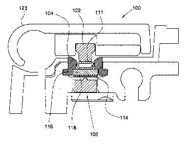
[0021] Figure 6 is a detail of area 6 in Figure 4. The following should
be viewed in
light of Figures 1 through 6. Pressure sensing assembly 100 for infusion pump
102 includes
tubing guide 104, displaceable load assembly 106, load cell 108, and
displacement assembly
110. The tubing guide is arranged to receive tubing 111 for the infusion pump.
The
displaceable load assembly is at least partially disposed within the tubing
guide and includes
at least one surface 112 facing in dircction D1. The load cell faces the load
assembly in
direction D1. The displacement assembly is engaged with the tubing guide,
faces surface 112
in direction D2, opposite the direction D1, and exerts force F1 on the load
assembly in
4
CA 02862801 2019-07-25
WO 2013/115852
PCT/US2012/054460
direction Dl. The load cell is arranged to detect force F2, greater than the
force Fl, acting on
the load cell in direction D2. In an example embodiment, the tubing guide
includes axis Al,
the tubing includes longitudinal axis A2 co-linear with Al, and D1 and D2 are
orthogonal to
Al /A2, for example, D1 is toward Al/A2 and D2 is away from Al /A2.
[0022] As further described below, thc load assembly is displaceable in
directions D1
and D2, for example in response to a load acting on the load assembly, for
example,
associated with compression of the tubing and pressure inside the tubing. In
an example
embodiment, assembly 100 includes shim 114 placed between the load assembly
and the load
cell. The shim is used to place a gap between the load assembly and the load
cell, due to
tolerance variances for example, within an acceptable range. For example, the
size of gap 115
is controlled by the thickness of the shim such that the gap is large enough
to prevent the
shim from touching the load cell, to enable zeroing of the load cell, but is
small enough to
maintain desired sensitivity. That is, since displacement of the load assembly
toward the load
cell is proportional to the magnitude of F2, the gap is minimized such that
the smallest
magnitude possible for F2 causes the shim to contact the load cell. The shim
is selected as
needed according to any gap between the load assembly and the load cell and
the particular
variances in respective tolerances for component parts in assembly 100.
[0023] In an
example embodiment, the load assembly includes load plate 116 and
attraction plate 118 fixed to the load plate. Plate 118 includes surface 112
upon which Fl is
exerted. Plate 116 includes surface 120 in contact with the tubing. Plates 116
and 118 can be
made of any material known in the art and can be fixed to each other using any
means known
in the art. Further information regarding plates 116 and 118 is provided
below.
[0024] In an
example embodiment, assembly 100 includes pusher assembly 121
displaceable in direction D2 to assume a fixed position, for example, as shown
in Figure 4. In
an example embodiment, assembly 121 includes pusher 122 engaged with door 123.
For
example, the door swivels shut to engage the pusher with the tubing. In the
fixed position,
assembly 122 engages the tubing and at least partially compresses the tubing.
The
compression of the tubing by assembly 122 results in at least a portion of
force F2 operating
on the load assembly. Thus, the load cell is arranged to detect force F2 in
response to the
disposition of the pusher assembly in the fixed position, and as further
described below, a
variation in force F2, for example, related to pressure within the tubing,
with the pusher
assembly in the fixed position.
5
CA 02862801 2019-07-25
WO 2013/115852
PCT/US2012/054460
[0025] Unlike
the configuration described above, assembly 110 operates on the load
assembly to attract, draw, or pull the load assembly toward the tubing guide.
That is, the load
assembly is pulled toward the tubing guide, rather than being pushed toward
the tubing guide.
Stated otherwise, the load assembly is pulled away from the load cell, rather
than being
pushed away from the load cell. Force F1 acts on a portion of the load
assembly facing
toward the tubing and tubing guide to pull the load assembly away from the
load center. In
contrast, in the configuration described above, a force from a resilient
component acts on a
portion of a load plate facing a load cell to push the load plate away from
the load cell.
[0026] In an
example embodiment, the displacement assembly includes a plurality of
magnets 110A-110D and plate 118 is at least partially made of magnetic
material. The
magnets are fixed to the tubing guide and exert magnetic force F1 on the
attraction plate,
urging the attraction plate, and the load plate, in direction D1 away from the
load cell. In the
example shown, four magiets are used. In an example embodiment, rare earth
magnets are
used. It should be understood that other numbers, configurations, and types of
magnets can be
used. The magnets can be fixed to the tubing guide using any means known in
the art. For
example, the magnets can be placed in counter-bores 126 in surface 128 of the
tubing guide
such that the magnets are recessed from the surface, are even with the
surface, or protrude
past the surfacc. Thus, as long as force Fl in direction D1 from the magnets
is greater than
force F2 in direction D2 on the load plate, the magnets draw the attraction
plate into contact
with the magnets or the tubing guide (if the magnets are recessed into the
tubing guide).
[0027] In an
example embodiment, four (Nd-Fe-B) magnets with respective diameters
of 0.0625" and respective thicknesses of 0.021" are press fit into respective
bores 126 in the
tubing guide. In an example embodiment, the magnets also are glued within the
bores. In an
example embodiment, the attraction plate is made of martensitic 17-4 PH
stainless steel and
is bonded or heat staked to the load plate. In an example embodiment, the shim
is metallic
and is fixed to the attraction plate by laser welding or other bonding.
[0028] The
displacement assembly lifts the load assembly (in the absence of F2 or
when greater than F2) off of the load cell, for example, holds the shim from
contacting ball
130 of the load cell to enable detection of force F2. For example, when the
tubing is properly
positioned in the tubing guide and the pusher assembly is engaged with the
tubing, the
magnitudc of Fl is set such that a forcc associated with the compression of
the tubing in the
proper position in the tubing guide results in F2. The detection of F2 acts as
a confirmation
that the tubing is properly positioned in the tubing guide. Force F2 can be a
composite of the
6
CA 02862801 2019-07-25
WO 2013/115852
PCT/US2012/054460
reaction of the tubing in direction D2 to the loading platc which extends in
direction D1 to
compress the tubing in direction D1, for example, as shown in Figure 4, and
the reaction of
the tubing to the pusher assembly, which compresses the tubing in direction
D2.
[0029] The
displacement assembly (in the absence of F2 or when greater than F2)
also holds the shim from contacting ball 130 to enable calibration and zeroing
of the load
cell. For example, when the tubing is removed from the tubing guide, the
displacement
assembly draws the load assembly off the load cell to a "no tubing" or "no
load" position,
which can be used as a benchmark for zeroing and calibrating. F1 also acts to
prevent the
load assembly from sticking in a loaded position (F2 causes the load assembly
to contact the
load cell). That is, after F2 causes the load assembly to engage the load cell
and is then
removed, F1 causes the load assembly to displace to the desired "no load"
position.
[0030] In an
example embodiment, assembly 100 functions as a downstream pressure
monitor for the infusion pump. For example, assembly 100 can be used to detect
air bubbles
in fluid being infused through the tubing. Such bubbles can be dangerous for a
patient
receiving the fluid. In this situation, the fluid can be considered to be
substantially
incompressible. As fluid is being infused through the tubing with the pusher
assembly in the
fixed position, force F2, generated by the compression of the tubing by the
pusher and load
asscmblies and by thc presence of the infused fluid, remains relatively
constant. However, if
an air bubble flows through the fluid between the pusher and load assemblies,
there will be a
drop in F2 due to the compression of the air bubble by the fluid. For example,
as the fluid
passes into narrower portion NP of the tubing, the pressure on the fluid
increases. Since the
air bubble is compressible compared to the fluid, as the air bubble enters NP,
the increase in
fluid pressure surrounding the bubble compresses the bubble, reducing the
pressure exerted
by the fluid on the tubing walls, and thus, on the load cell. The load cell
detects the pressure
drop and transmits an alarm signal.
[0031] It will
be appreciated that various of the above-disclosed and other features
and functions, or alternatives thereof, may be desirably combined into many
other different
systems or applications. Various presently unforeseen or unanticipated
alternatives,
modifications, variations, or improvements therein may be subsequently made by
those
skilled in the art which are also intended to be encompassed by the following
claims.
7