Note : Les descriptions sont présentées dans la langue officielle dans laquelle elles ont été soumises.
CA 02863482 2014-09-12
CONNECTOR HAVING MULTIPLE DIRECTION CONNECTIVITY
TECHNICAL FIELD
[0001] The present invention relates generally to connectors for securing
objects, such as cargo, via flexible strapping and specifically relates to a
connector
type referred to as "E-Track Connectors."
BACKGROUND
[0002] Connectors, commonly referred to as "E-Track Connectors" are used in
various applications, such as in the transportation industry, to secure
flexible
strapping (e.g., webs, belts or the like) to load rails or tracks (e.g.,
commonly
referred to as E-Track) mounted on a transporting surface (e.g., a side, floor
or
ceiling of a container, truck hold, load bed, dolly, or other cargo areas). In
one
specific use, the strapping or straps are used for holding one or more objects
in
partially loaded containers or areas so that they will not shift (e.g., within
the
container or area) and cause damage by either striking (e.g., against sides of
a
container or other items) or other loss. Such connectors are commonly used for
trucks, railroad cars, airplanes and shipping containers. In one example, the
load
rails include a sequence of lock-down apertures.
[0003] Each lock-down aperture is capable of accepting an industry standard
complementary buckle or clip. The buckle or clip is connected/connectable to
the
strapping or straps. The straps can be secured (e.g., wrapped over and around)
cargo) in any desired or needed fashion. The buckle or clip is then secured to
a
desired/appropriate aperture point of a load rail. The straps can then be
tightened
(e.g., via ratchet, winch, turn buckle, etc.).
1
CA 02863482 2014-09-12
[0004] It is also possible to have a load rail with just a single aperture.
Such a
single aperture load rail is typically placed at a strategic location so that
the
otherwise need to select a desired/appropriate aperture point is a non-issue.
[0005] Load rails, albeit containing multiple or single aperture point(s)
all have
apertures that are generally rectangular, and thus have a major, elongate
opening
dimension and a minor, smaller opening dimension. The buckle or clip has
commentary dimensions so that the buckle or clip interfaces with the
respective
aperture point in a single orientation. Within a load rail with plural
apertures, all of
the apertures are oriented in the same direction. Thus, for a load rail with
plural
apertures, the load rail is mounted with the entirety of the apertures
arranged in an
orientation direction/line (e.g., left-right, fore-aft, vertical, horizontal).
Similarly, a
load rail with single aperture, once mounted and thus fixed in place has a
certain,
single orientation direction. Accordingly, the buckle or clip that mates with
the load
rail must conform to the orientation direction of the aperture(s) in the load
rail.
[0006] For some locations/applications, the multiple load rails are used to
allow
different orientation (e.g., horizontal and vertical). Further for some
applications,
multiple connector anchors are used that have different aperture orientation.
These
various applications add material and labor cost to install additional
connector
anchors.
[0007] Thus, it is desired to provide an improved connector anchor that
does not
suffer from these and other disadvantages.
BRIEF SUMMARY
[0008] The following presents a simplified summary of the invention in
order to
provide a basic understanding of some example aspects of the invention. This
summary is not an extensive overview of the invention. Moreover, this summary
is
not intended to identify critical elements of the invention nor delineate the
scope of
the invention. The sole purpose of the summary is to present some concepts of
the
2
CA 02863482 2014-09-12
invention in simplified form as a prelude to the more detailed description
that is
presented later.
[0009] According to one aspect, a connector has at least one aperture for
receiving a buckle clip. The aperture has two crossed aperture extent
portions.
Each aperture extent portion has a different orientation such that the buckle
clip
received within the at least one aperture can be at one of two different
orientations.
[0010] According to another aspect, a connector anchor has an axis and an
aperture for receiving a buckle clip. The aperture has a first extent portion
extending in a first direction. The aperture has a second extent portion
extending
from the first extent portion in a second direction transverse to the first
direction.
The first direction extends substantially parallel to the axis.
[0011] According to yet another aspect, a connector anchor has a
longitudinal
axis and at least two spaced apart apertures each of which may receive a
buckle
clip. Each of the apertures has a first extent portion and a second extent
portion.
The first extent portion of each of the apertures extends in a direction along
the
longitudinal axis of the connector anchor.
[0012] It is to be understood that both the foregoing general description
and the
following detailed description present example and explanatory embodiments of
the
invention, and are intended to provide an overview or framework for
understanding
the nature and character of the invention as it is claimed. The accompanying
drawings are included to provide a further understanding of the invention and
are
incorporated into and constitute a part of this specification. The drawings
illustrate
various example embodiments of the invention, and together with the
description,
serve to explain the principles and operations of the invention.
BRIEF DESCRIPTION OF THE DRAWINGS
[0013] The foregoing and other aspects of the present invention will become
apparent to those skilled in the art to which the present invention relates
upon
3
CA 02863482 2014-09-12
reading the following description with reference to the accompanying drawings,
in
which:
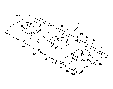
[0014] Fig. 1 is a perspective view of a connector anchor, according to one
aspect;
[0015] Fig. 2 is a plan view of the connector anchor illustrated in Fig. 1;
[0016] Fig. 3 is a cross-sectional view of the connector anchor illustrated
in Fig.
2, taken approximately along line 3-3 in Fig. 2;
[0017] Fig. 4 is a cross-sectional view of the connector anchor illustrated
in Fig.
2, taken approximately along line 4-4 in Fig. 2;
[0018] Fig. 5 is an enlarged cross-sectional view of the connector anchor
illustrating a buckle clip being inserted into an aperture of the connector
anchor;
[0019] Fig. 6 is an enlarged cross-sectional view of the connector anchor,
similar
to Fig. 5, illustrating a buckle clip inserted into the aperture of the
connector anchor
in a retained position; and
[0020] Fig. 7 is a plan view of the connector anchor illustrating the
different
orientations that buckle clips may be received in the connector anchor and
straps
may extend from the connector anchor.
DETAILED DESCRIPTION
[0021] An example embodiment that incorporates one or more aspects of the
present invention is described and illustrated in the drawings. The
illustrated
example is not intended to be a limitation on the present invention. It will
be
understood that one or more aspects of the present invention can be utilized
in
other embodiments and other types of devices. Moreover, certain terminology is
used herein for convenience only and is not to be taken as a limitation. Still
further,
in the drawings, the same reference numerals are employed for designating the
same elements.
4
CA 02863482 2014-09-12
[0022] An example track or connector anchor 120, according to one aspect,
is
illustrated in Figs. 1 - 2. The connector anchor 120 is intended for use on
interior
walls, ceilings and floors of box trucks, trailers and containers that store
and
transport cargo. The connector anchor 120 is intended to receive and use known
E-track style buckle clips 100 (Figs. 5 ¨7) to retain the cargo.
[0023] The connector anchors 120 are available in any number of suitable
lengths. For example, the lengths of the connector anchors 120 can be 5', 4',
3', 2'
or other lengths depending on the application that the connector anchors will
be
used in. The connector anchors 120 are secured to mounting structure M (Figs.
5 ¨
6) on the interior of the box trucks, trailers and containers by suitable
means. For
example, fasteners 101 that extend though small round holes along the outside
edges of the track. The connector anchors 120 may be mounted to the box
trucks,
trailers and containers in any suitable orientation, such as in horizontal and
vertical
directions. It will be apparent however, that the connector anchors 120 could
be
mounted at an angle relative to horizontal or vertical.
[0024] The connector anchor 120 (Fig. 1) is elongate and has a
longitudinally
extending axis A. The connector anchor 120 is made from any suitable material
having sufficient strength for the intended purpose, such as a metal like
steel or
aluminum. The connector anchor 120 is typically formed by any suitable method,
such as by rolling, extruding or stamping. The connector anchor 120 is
typically
provided with a galvanized or painted finish.
[0025] The connector anchor 120 includes a main mounting portion 122. The
connector anchor 120 also has a pair of flanges 124 extending from opposite
lateral
sides of the main mounting portion 122. Each of the flanges 124 extends
substantially parallel to and is offset from the plane containing the main
mounting
portion 122 by a distance D, as illustrated in Figs. 3 ¨ 4. Each of the
flanges 124 is
connected to the main mounting portion 122 by a respective connecting portion
126.
[0026] The connector anchor 120 is secured by suitable fasteners 101, such
as
screws, nails or the like as illustrated in Figs. 5 - 6, to mounting structure
M of the
CA 02863482 2014-09-12
transporting vehicle, such as a floor, ceiling or wall. The fasteners 101
extend
through openings 128 formed in the flanges 124. Each of the flanges 124 has
multiple openings 128 spaced along the longitudinal extent of the flange.
[0027] The connector anchor 120 (Figs. 1 - 2), according to at least one
aspect,
has at least one aperture 140 for receiving a buckle clip 100. In the
illustrated
aspect, the connector anchor 120 has several apertures 140. However, it will
be
apparent that any number of apertures 140, including just a single aperture,
could
be provided in the connector anchor 120. It will be apparent that any size of
aperture 140 could be provided that is appropriate for the length of the
connector
anchor 120 and the intended size of the buckle clip 100 to be used.
[0028] The aperture 140 is defined by a pair of aperture extents 142, 144
that
form an X or cross shape. The aperture extents 142, 144 are of similar
rectangular
size. Each of the aperture extents 142, 144 is configured as a rectangular
shape
and suitable size to receive a known buckle clip. The aperture extents 142,
144
intersect or are connected to one another at their respective center regions.
Each
aperture extent 142, 144 is configured so as to be engagable by the buckle
clip 100.
[0029] The aperture extents 142, 144, are arranged so they extend in a
relative
orthogonal orientation pattern. Thus, when the buckle clip 100 is to be
connected
within the aperture 140, the orientation of the aperture extent 142, 144 used
can be
selected from two different orientations, as illustrated in Fig. 7. Different
orientations of the buckle clip 100 may be required or convenient by the
desired
orientation of the cargo securing strap 102. Orientation of the buckle clip
100 may
be more important than the length of the strap 102, webbing, rope or chain to
which
the buckle clip 100 is attached. The needed orientation of the buckle clip 100
and
length of strap 102, webbing, rope or chain, of course, depends on the
requirements
of the cargo being transported.
[0030] Each of the aperture extents 142, 144 has a length L (Fig. 2) and a
width
W extending perpendicular to the length. The orientation of each aperture
extent
142 and its associated length L extends transversely, and preferably
orthogonally or
6
CA 02863482 2014-09-12
. .
perpendicularly, relative to axis A of the connector anchor 120. While the
length L
of the aperture extent 142 is illustrated as extending perpendicular to the
axis A, it
will be apparent that the orientation of aperture extent 142 can be oriented
at any
desired angle relative to the axis A of the connector anchor 120.
[0031] The length L of each of the aperture extents 144 preferably
extends in a
direction substantially along or parallel to the axis A of the connector
anchor 120.
While the associated length L of the aperture extent 144 is illustrated as
preferably
extending parallel to the axis A, it will be apparent that the orientation of
the length
of the aperture extent 144 can be oriented at any desired angle relative to
the axis A
of the connector anchor 120.
[0032] In the illustrated example, the relative orientations are such
that the
aperture extents 142, 144 extend substantially perpendicular (e.g., at or near
90 )
relative to each other. It is contemplated that different relative
orientations (e.g.,
different that 90 ) between the aperture extents 142, 144 are possible.
[0033] Each aperture 140 has two crossed aperture extents 142, 144.
Specifically, each aperture extent 142, 144 is elongated with the length L
being
greater than the width W. Each aperture extent 142, 144 is generally sized,
configured, etc. similar to a single aperture that would be present within the
known
E-track style connectors so the known buckle clips 100 can be used. Also,
although
not required, each aperture extent 142, 144 may have straight (as
illustrated),
arcuate, tapered surface segments defining the aperture extents so as to
effectively
be engagable by a buckle clip.
[0034] Each aperture extent 142, 144 has a different orientation such
that the
buckle clip received within the at least one aperture can be at each of two
different
orientations. The apertures 140 of the connector anchors 120 are shown as
cross
or X shape in the illustrated aspect. However it will be apparent that in L-
shape, V-
shape or T-shaped configuration could equally be employed without departing
from
the spirit and scope of the illustrated aspect.
7
CA 02863482 2014-09-12
[0035] The connector anchor 120 has an overall average thickness T (Figs. 3
-
4). Another feature of the connector anchor 120 is that the tabs 160 that
define the
aperture extents 142, 144 of the aperture 140 that are displaced outside of
the
thickness T of the mounting portion 122 of the connector anchor. That is, the
tabs
160 defining at least some of each aperture 142, 144 extend outside of the
dimensional thickness T of the mounting portion 122 of the connector anchor
120.
However, in one example, the displaced material from a manufacturing operation
forming the tabs 160 does not extend beyond the depth D of the cavity formed
in
the bottom of the connector anchor 120, as viewed in Figs. 5 and 6. This
feature of
the portions 160 provides additional strength to the connector anchor 120
adjacent
an aperture extent 142 or 144. This feature enables the buckle clip to be
inserted
into and engage an aperture extent 142 or 144 with minimal effort during
attachment to the connector anchor 120. This may be desirable in some
applications. The tabs 160 are illustrated as extending at an angle of about
450
relative to a plane containing the mounting portion 122 of the connector
anchor 120.
It will be understood that the tabs 160 could extend any suitable angle.
[0036] As is known, the buckle clip 100 has a strap 102 (Figs. 5¨ 7),
chain,
cable, rope or other flexible securement structure attached for securing
cargo. The
buckle clip 100 has a base 104 with a notch. The buckle clip 100 also has a
spring
loaded clip member 106 with a notch opposite the notch in the base 104. The
clip
104 is pivotable relative to the base 104 when manually retracted to
temporarily
decrease the extent or width of the buckle clip 100, as illustrated in Fig. 5.
Once the
buckle clip member 106 is in position within one of the aperture extents 142,
144 of
one of the apertures 140 the spring clip member 106 is released. The buckle
clip
100 is then releasably secured in the aperture 140, as illustrated in Fig. 6.
[0037] The strap 102 (e.g., the webbing, chain, cable, rope or other
flexible
securement structure) typically has a certain orientation as it extends from
the cargo
to the connector anchor 120. Thus, the strap 102, chain, cable, rope or other
flexible securement structure extends in a direction so the selected aperture
extent
8
CA 02863482 2014-09-12
. .
142, 144 of the aperture 140 to provide relatively low twist and stress of the
strap
102, webbing, cable, rope or chain.
[0038] Fig. 7 illustrates for example purposes, that the connector 120
has two
different buckle clips 100 secured in apertures in the connector anchor 120 at
two
different orientations. The orientations are shown to be basically
perpendicular
(e.g., at or near 90 ) to each other. It is contemplated that different
orientations
(e.g., different that 90 ) are possible. Thus, Fig. 7 shows how known buckle
clips
100 can connect with the connector anchor 120 in accordance with at least one
aspect at different angles at the same time.
[0039] Some of example advantages of the connector anchor 120, according to
one aspect, are that a single connector anchor, constructed according to at
least
one aspect, can provide multiple directions of attachment for multiple buckle
clips
100/straps 102. Further, possibly fewer connector anchors 120 could be
utilized for
use on interior walls and floors of box trucks, trailers and containers that
store and
transport cargo because of greater functionality of each connector anchor.
Also, it
is to be appreciated that objects with or without webbing attached thereto
could be
utilized with the connection anchor. Some examples include hooks, board
holders,
etc. Also, certain orientations of such objects could be preferable (e.g.,
board
holders may have a preferred orientation).
[0040] Each connector anchor 120 in accordance with at least one
aspect can
do the job of both of the previously known E-Tracks that consist of tracks
with
apertures extending only in the horizontal or vertical directions. Each
connector
anchor 120 has the ability to receive the standard E-track buckle clip 100
horizontally, vertically, or both at the same time along different parts of
the
connector anchor 120. Such multiple connecting orientations of the buckle clip
100
provides a user more options when securing cargo. The connector anchor 120
could be mounted and employed in a box trucks, trailers and containers without
prior knowledge of which mounting direction (horizontal or vertical) would be
best
for their cargo securement needs. The orientation of the buckle clip 100 can
also
9
CA 02863482 2014-09-12
be changed as needed or desired after the initial connection and orientation
is
selected. Such flexibility provides for less concern, worry, and effort to the
user.
[0041] The
invention has been described with reference to the example aspects
described above. Modifications and alterations will occur to others upon a
reading
and understanding of this specification. Examples incorporating one or more
aspects of the invention are intended to include all such modifications and
alterations insofar as they come within the scope of the appended claims.