Sélection de la langue

Search

Sommaire du brevet 2863603 

Énoncé de désistement de responsabilité concernant l'information provenant de tiers

Une partie des informations de ce site Web a été fournie par des sources externes. Le gouvernement du Canada n'assume aucune responsabilité concernant la précision, l'actualité ou la fiabilité des informations fournies par les sources externes. Les utilisateurs qui désirent employer cette information devraient consulter directement la source des informations. Le contenu fourni par les sources externes n'est pas assujetti aux exigences sur les langues officielles, la protection des renseignements personnels et l'accessibilité.

Disponibilité de l'Abrégé et des Revendications

L'apparition de différences dans le texte et l'image des Revendications et de l'Abrégé dépend du moment auquel le document est publié. Les textes des Revendications et de l'Abrégé sont affichés :

  • lorsque la demande peut être examinée par le public;
  • lorsque le brevet est émis (délivrance).
(12) Brevet: (11) CA 2863603
(54) Titre français: DOME CERAMIQUE DE RUPTURE POUR REGULATION DE PRESSION
(54) Titre anglais: CERAMIC RUPTURE DOME FOR PRESSURE CONTROL
Statut: Accordé et délivré
Données bibliographiques
(51) Classification internationale des brevets (CIB):
  • E21B 34/10 (2006.01)
  • E21B 21/08 (2006.01)
  • E21B 33/10 (2006.01)
(72) Inventeurs :
  • PETROWSKY, CONRAD (Canada)
(73) Titulaires :
  • ARMOR TOOLS INTERNATIONAL INC.
(71) Demandeurs :
  • ARMOR TOOLS INTERNATIONAL INC. (Canada)
(74) Agent: BENNETT JONES LLP
(74) Co-agent:
(45) Délivré: 2015-11-03
(22) Date de dépôt: 2014-09-10
(41) Mise à la disponibilité du public: 2015-01-26
Requête d'examen: 2014-10-24
Licence disponible: S.O.
Cédé au domaine public: S.O.
(25) Langue des documents déposés: Français

Traité de coopération en matière de brevets (PCT): Non

(30) Données de priorité de la demande: S.O.

Abrégés

Abrégé français

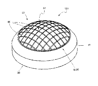
A one-time-use pressure-actuated conduit closure is provided, to selectively withstand fluid pressure from one side of the device until the closure is removed remotely, the closure device being a frangible dome designed to withstand fluid pressures from one side but to rupture upon application of higher pressure on its other side, which provides a mechanism to isolate downhole fluid under (high) pressures in part of a well during operations for a period of time selected by an operator, and then to remove the isolation by breaking the rupture dome remotely by application of extra fluid pressure or other forces from surface. The frangible dome has features in at least one surface to guide and control its breakage to provide controlled shard sizes and shapes and a predictable opening for minimal obstruction of the conduit when broken away.


Abrégé anglais

Un dispositif de fermeture de conduit à usage unique activé par pression est présenté et peut supporter de manière sélective la pression de liquide provenant d'un côté du dispositif jusqu'à ce que le dispositif de fermeture soit retiré de manière distante, le dispositif de fermeture comportant un dôme frangible conçu pour supporter les pressions de liquide d'un côté, mais pour se rompre lorsqu'une pression supérieure est exercée sur l'autre côté, et fournit un mécanisme permettant d'isoler le fluide de fond de trou lorsque la pression est élevée dans une partie d'un puits pendant l'exploitation pendant une période sélectionnée par un opérateur, puis d'enlever l'isolation en brisant le dôme de rupture de manière distante par l'exercice d'une pression supplémentaire de liquide ou d'autres forces à la surface. Le dôme frangible présente, sur au moins une surface, des caractéristiques servant à guider et contrôler la rupture pour que la taille et la forme des épaufrures soient contrôlées et assurer une ouverture prévisible d'obstruction minimale du conduit lors de la rupture.

Revendications

Note : Les revendications sont présentées dans la langue officielle dans laquelle elles ont été soumises.


CLAIMS
1. A rupture
dome for use as a breakable seal for a conduit formed by
tubing formed of a breakable material, including:
A circular-shaped body with dome-shaped cross-section with
a. A convex side;
b. A concave side;
c. An attached circumferential rim for mounting to a seal
on the inside of the tubing or a fitting on the tubing;
ii. One side having a pattern of features included in its surface
to guide the breakage of the rupture dome, the pattern of
features comprising at least a linear depression or ridge in or
on the surface of the side;
iii. The portion of the body defined between the convex side
and concave side forming a breakaway section, being
frangible, to hold high fluid pressure applied to the convex
side, and to break when fluid pressure applied to the
concave side exceeds a threshold;
iv. The breakaway section when ruptured as a result of
application of pressure to the concave side which exceeds
the threshold, breaks into pre-determined fragments defined
at least in part by the features included in its surface.
2. The rupture dome of claim 1 made of ceramic.
3. The
rupture dome of claim 1 wherein the pattern of features
includes at least one of:
i. A feature with a circuler pattern with the same or similar
diameter as the inner diameter of the tubing;
ii. A series of symmetrical grooves in a pattern to define the
size of fragments into which the rupture dome will break
when ruptured;
iii. A pattern of grooves or inclusions or ridges in the surface to
encourage the dome to rupture in specific places to form
pre-determined debris fragments.
4. The
rupture dome of claim 1 with the rim formed to mate with a
fixture in the tubing string so that the dome may be fitted and
sealed, ruptured, then removed and replaced, so that the

removable seal provided by the rupture dome may be easily
repeated.
5. The rupture dome of claim 1 where the high fluid pressure
sustained is approximately 10,000 psi.
6. The rupture dome of claim 1 made to rupture when fluid pressure
applied to the concave side exceeds the fluid pressure on the
convex side by a small but useful differential.
7. The rupture dome of claim 6 where the pressure differential is
25% of the maximum pressure sustainable by the convex side.
8. The rupture dome of claim 1 for 2 3/8" tubing.
9. The rupture dome of claim 1 for 2 7/8" tubing.
10. The rupture dome of claim 1 where the pattern of features is a
cross-hatch of grooves or ridges or inclusions.

Description

Note : Les descriptions sont présentées dans la langue officielle dans laquelle elles ont été soumises.


CA 02863603 2014-09-10
'
CERAMIC RUPTURE DOME FOR PRESSURE CONTROL
FIELD OF INVENTION
The present invention relates generally to a one-time-use pressure-
actuated valve or closure to selectively withstand fluid pressure from one
side of the
device until the closure is removed remotely. This is done by configuring the
device
as a frangible dome which can withstand high pressures from one side but will
rupture in the presence of high pressure on its other side. The rupture dome
provides
a mechanism to isolate downhole fluid under high pressures during initial
operations
in a drillstring in a well for a period of time selectable by the driller or
operator, and
-Io then to remove the isolation by breaking the rupture dome remotely by
application of
extra fluid pressure or other forces from surface.
These operations are useful in directional, horizontal or deviated wells
during snubbing, bridge-plug retrieval or zone separation operation in
combination
with packers and/or completion strings. The dome of this device provides
pressure
isolation for vertical as well as non-vertical operations which can be opened
without
wireline, and can be used in conjunction with other equipment such as
subassemblies which include landings for retrieval, or other functions.
BACKGROUND OF THE INVENTION
In drilling, completion or service operations in a deviated well, it is
sometimes important to be able to seal the tubing string to isolate production
or other
pressurized zones of the wellbore.
In the past, tubing end-plugs have been used during injection of tubing
into such a well, the plugs generally being a metallic or aluminum disc
attached to the
bottom of the tubing string prior to injection, and then the removal of the
metallic disc
from the tubing string at or near bottom hole. An example is found in
US244,042
Farrar (1881). This has the undesirable effect of leaving the metal at the
bottom
workface of the wellbore which is difficult or expensive to remove and can
interfere
VVSLega1\071761\00008\10775848v3

CA 02863603 2014-09-10
with further drilling or other operations. These devices have only been run at
the
bottom of a tubing string.
Another mechanism sometimes seen is the use of an fis nipple,
consisting of multiple profiles to receive a variety of plug devices via
wireline delivery
downhole. These mechanisms provide for a single plug, and while unpluggable
and
repluggable, are constrained by the plug delivery mechanism ¨ that is,
wireline plugs
may be difficult to retrieve from deep deviated or horizontal wellbores, and
may be
impossible to inject and refit in non-vertical orientations. Additionally, if
such a plug
fitting fails during operations, the wireline plug may become a projectile,
and two
lo wireline plugs cannot or cannot easily be installed during or for
operations. Similarly,
multi-profile landing nipples to receive a variety of plugs are manufactured
under the
Baker trade name.
Rupture domes have been used in similar situations downhole. For
instance, a system providing a "Frangible Pressure Seal" is disclosed in
Canadian
Patent Application 2,228,728 by Frazier (CA'728). In that case ceramic shells
with a
circular seating face and a radial curvature are provided as a breakable seal
for
inclusion in a downhole subassembly. In CA'728, the ceramic disc is formed
with a
precise arcuate shape (in cross-section) to offer maximum pressure resistance.
CA'728 is designed to provide a strong barrier to fluid pressures, yet be
capable of
being broken by wielding a breaking implement downhole (such as by dropping a
bar
down the tubing). This design would be unsuitable, for instance, in a deviated
or non-
vertical well-bore's tubing string because the bar or breaking implement could
not be
propelled by gravity alone should the non-vertical portion of the wellbore be
a very
great distance, or should the curvature of the deviated bore impair the
breaking tool's
travel velocity (or striking force). Additionally, where the domes of '728 are
ruptured,
the resulting passage may be irregular and restrict fluid flow in the tubing's
bore past
the remnants of the dome. As well, resulting fragments may be irregular or
large
which may interfere with fittings, drilling, or other well bore
characteristics or
operations.
- 2 -
VVSLega1\071761\00008\10775848v3

CA 02863603 2014-09-10
SUMMARY OF THE INVENTION
To mitigate some of the problems of the prior art, the rupture dome of
this invention is manufactured of a frangible material with a specific arcuate
domed
shape and with included features in at least one surface of the domed shape
which
guide and control fragmentation of the dome when it is broken so that the
pieces of
the ruptured dome are of a controlled size and shape designed to avoid
plugging or
hanging in the wellbore or any associated equipment. The frangible dome may be
made of a material such as certain ceramics, glass, cast metal, dissolvables,
or any
suitable material, should not react negatively with or interact to cause
damage to the
well or associate equipment.
In an embodiment, a rupture dome for use as a breakable seal for a
conduit formed by tubing formed of a breakable material, is provided, which
includes:
a. A circular-shaped body with dome-shaped cross-section with
1. A convex side
2. A concave side
3. An attached circumferential rim for mounting to a
seal on
the inside of the tubing or a fitting on the tubing
b. One side having features included in its surface to guide the
breakage of the rupture dome
c. The portion of the body defined between the convex side and
concave side forming a breakaway section, being frangible,
designed to hold high fluid pressure applied to the convex side,
and to break when fluid pressure applied to the concave side
exceeds a threshold
- 3 -
VVSLega1\071761\00008\10775848v3

CA 02863603 2014-09-10
d.
The breakaway section when ruptured as a result of application
of pressure to the concave side exceeds the threshold, designed
to break into pre-determined fragments defined at least in part by
the features included in its surface;
e. The dome may
also be ruptured using mechanical or other
forces.
BRIEF DESCRIPTION OF THE DRAVVINGS
Figure 1 is an illustrated elevation of a rupture donne from the top and
side.
Figure 2 is a side elevation of a rupture dome showing an embodiment
of groove and lip structures
Figures 3 and 3a are a cross-section of the rupture dome of Figure 2
along Une A-A, with Figure 3a providing an expanded detailed illustration of
an
embodiment of ball-end milled groove structures on the top surface of the
rupture
dome
DETAILED DESCRIPTION
The present invention provides for a rupture dome 100 for use as a
breakable seal in a subassembly (not shown). The rupture dome 100 is made with
an
outer circumference the edge of which 10 fits within the subassembly (flot
shown)
and is sealed to the subassembly which then seals the internai passageway of a
fluid
conduit (flot shown) such as a tubing string for use in a well. Generally, the
field to
which this invention is directed is the ou l and gas industry, more
particularly pressure
control in operations with respect to oil or gas wells, and even more
particularly,
deviated or non-vertical wells.
The rupture dome 100 is made of a frangible material such as a
ceramic. It has a domed shape, with a hollowed or concave side 20 and a convex
- 4 -
WSLega1\071761 \00008 \10775848v3

CA 02863603 2014-09-10
side 30. The arc of the concave 20 and convex 30 sides are, in an embodiment,
similar or equivalent, making the dome's curved body 40 of a relatively even
thickness.
Depending upon the diameter of the rupture dome 100, the thickness
and curvature of the dome's body 40 will differ, being designed to withhold a
predetermined range of fluid pressure from one side (applied to the convex
side 30)
and to break or rupture at a different but predetermined pressure threshold
from the
other side (applied to the concave side 20). In this way, the seal provided by
the
rupture dome 100 in the subassembly sealed to the tubing can be maintained,
isolating the sealed portion of the tubing from the rest of the well, until
pressure
above the designed rupture pressure is applied to the concave side 20 of the
rupture
dome 100.
In a preferred embodiment, the rupture dome is designed to withstand
10,000 psi from the high pressure bearing convex side 30 without breaking ,
but to
breakaway or rupture when the pressure at the other (concave) side 20 exceeds
the
pressure on the other (convex) side 30 by 10-15% of the maximum pressure the
dome's convex side can withstand. In one embodiment, the pressure dome can
withstand a pressure differential where pressure on the convex side is the
same as or
up to 10,000 psi greater than the pressure on the concave side before
rupturing, but
the pressure dome is designed so that it can withstand a pressure differential
where
the pressure on the concave side is 1500 psi greater than the pressure on the
convex side but will rupture if that pressure differential exceeds 1500 psi
(these
numbers are by example, and are an approximation of a preferred embodiment).
This
means that if the pressure dome was in an environment sealing a well bore with
pressure from formation of 9,000 psi, the dome could be ruptured by
application of
fluid pressure from surface equipment of 10,501 psi or greater (a pressure
differential
of over 1500 psi) under control of an operator. Similarly, if tested at a
pressure on the
convex side of 1,000 psi, the dome can be ruptured by applying 2,501 psi or
greater
to the concave side (a differential of greater than 1500 psi). These examples
are to
- 5 -
vvsLegid\071761\00008\10775848v3

CA 02863603 2014-09-10
=
show how the rupture pressure differential should be designed such that there
is a
small (something like 10-25% of the maximum pressure the convex side will
withstand) but significant (so that there is a reduced chance of accidentai
rupture)
pressure differential which can be applied to the concave side of the dome to
cause if
to rupture in a controllable (by manipulation of fluid pressure applied to the
concave
side) manner. In this way, the rupture dome may be purposefully ruptured by
selective application of pressure from surface to the concave side 20 to cause
the
dome to fail, rupture, and break the seal it previously formed. To provide
this
performance characteristic set, a ceramic rupture dome 100 with a 2 3/8" O.D.
will
-Io have a dome wall 40 thickness of approximately 0.2575" into which the
grooves
extend by 0.075" and feature lines 70, 90 formed or cut into the dome wall 40,
if
milled for example, by a 0.030" ball-end mill to a depth of about 0.075".
To ensure that the rupture dome, when ruptured, does flot break into
large, irregular and harmful fragments of dome material, which could hang in,
plug or
damage downhole equipment or tubing, a specific pattern may be included in a
surface of the rupture dome 100 ¨ in a preferred embodiment, the pattern may
be
included in the outer surface of the convex side 30. The patterns 50 can be a
symmetrical grid of features 60 in the outer surface of the convex side 30, or
can be
any suitable pattern, and can be included during the molding or forming stage
of
manufacture or machined or carved or otherwise made. In an embodiment, the
features may be milled using a 0.030" bail-end mill with 0.015" radius, or a
0.020 ball-
end mill with 0.010" radius in a squared grid pattern with feature lines 70
spaced
approximately 3/16 inches apart.
The feature pattern 50 of fines 70 in the surface of the convex side 30
of the rupture dome 100 are, in a preferred embodiment, within a radius 80
which is
also a feature line 90 in the same surface 30, which radius 80 is about or
slightly
smaller than the interior diameter of the subassembly (not shown). In a
preferred
embodiment, for use in a 2 3/8" O.D. tubing string seal with 2" ID., this
radius 80 will
be approximately 2". This permits the rupture dome to break away when ruptured
to
- 6 -
vvsLegal\071761900o8\10775848v3

CA 02863603 2014-09-10
leave a clean passageway bounded by the radius 80 feature line 90 once the
broken
parts of the rupture dome break and are removed from the seal, leaving an
essentially unimpaired passage.
The rupture dome 100 can have an outer circumferential wall 95 for
attachment to the subassembly (not shown).
The above-described embodiments of the invention are intended to be
examples only. Alterations, modifications and variations can be effected to
the
particular embodiments by those of skill in the art without departing from the
scope of
the invention, which is defined solely by the claims appended hereto.
-7-
VVSLega1\071761\00008\10776848v3

Dessin représentatif
Une figure unique qui représente un dessin illustrant l'invention.
États administratifs

2024-08-01 : Dans le cadre de la transition vers les Brevets de nouvelle génération (BNG), la base de données sur les brevets canadiens (BDBC) contient désormais un Historique d'événement plus détaillé, qui reproduit le Journal des événements de notre nouvelle solution interne.

Veuillez noter que les événements débutant par « Inactive : » se réfèrent à des événements qui ne sont plus utilisés dans notre nouvelle solution interne.

Pour une meilleure compréhension de l'état de la demande ou brevet qui figure sur cette page, la rubrique Mise en garde , et les descriptions de Brevet , Historique d'événement , Taxes périodiques et Historique des paiements devraient être consultées.

Historique d'événement

Description Date
Paiement d'une taxe pour le maintien en état jugé conforme 2024-08-23
Requête visant le maintien en état reçue 2024-08-23
Représentant commun nommé 2019-10-30
Lettre envoyée 2017-02-15
Inactive : Transfert individuel 2017-02-14
Accordé par délivrance 2015-11-03
Inactive : Page couverture publiée 2015-11-02
Exigences de modification après acceptation - jugée conforme 2015-08-28
Lettre envoyée 2015-08-28
Modification après acceptation reçue 2015-08-25
Préoctroi 2015-08-25
Inactive : Taxe finale reçue 2015-08-25
Un avis d'acceptation est envoyé 2015-07-13
Lettre envoyée 2015-07-13
Un avis d'acceptation est envoyé 2015-07-13
Inactive : Q2 réussi 2015-07-09
Inactive : Approuvée aux fins d'acceptation (AFA) 2015-07-09
Modification reçue - modification volontaire 2015-06-05
Inactive : Dem. de l'examinateur par.30(2) Règles 2015-03-06
Inactive : Rapport - Aucun CQ 2015-03-06
Inactive : Page couverture publiée 2015-02-03
Lettre envoyée 2015-01-26
Avancement de l'examen jugé conforme - alinéa 84(1)a) des Règles sur les brevets 2015-01-26
Demande publiée (accessible au public) 2015-01-26
Lettre envoyée 2014-11-26
Inactive : CIB en 1re position 2014-11-25
Inactive : CIB attribuée 2014-11-25
Inactive : CIB enlevée 2014-11-25
Inactive : CIB attribuée 2014-11-25
Inactive : Avancement d'examen (OS) 2014-10-24
Exigences pour une requête d'examen - jugée conforme 2014-10-24
Inactive : Taxe de devanc. d'examen (OS) traitée 2014-10-24
Toutes les exigences pour l'examen - jugée conforme 2014-10-24
Requête d'examen reçue 2014-10-24
Inactive : Certificat dépôt - Aucune RE (bilingue) 2014-09-22
Demande reçue - nationale ordinaire 2014-09-22
Inactive : Pré-classement 2014-09-10
Inactive : CQ images - Numérisation 2014-09-10

Historique d'abandonnement

Il n'y a pas d'historique d'abandonnement

Titulaires au dossier

Les titulaires actuels et antérieures au dossier sont affichés en ordre alphabétique.

Titulaires actuels au dossier
ARMOR TOOLS INTERNATIONAL INC.
Titulaires antérieures au dossier
CONRAD PETROWSKY
Les propriétaires antérieurs qui ne figurent pas dans la liste des « Propriétaires au dossier » apparaîtront dans d'autres documents au dossier.
Documents

Pour visionner les fichiers sélectionnés, entrer le code reCAPTCHA :


Pour visualiser une image, cliquer sur un lien dans la colonne description du document (Temporairement non-disponible). Pour télécharger l'image (les images), cliquer l'une ou plusieurs cases à cocher dans la première colonne et ensuite cliquer sur le bouton "Télécharger sélection en format PDF (archive Zip)" ou le bouton "Télécharger sélection (en un fichier PDF fusionné)".

Liste des documents de brevet publiés et non publiés sur la BDBC .

Si vous avez des difficultés à accéder au contenu, veuillez communiquer avec le Centre de services à la clientèle au 1-866-997-1936, ou envoyer un courriel au Centre de service à la clientèle de l'OPIC.

({010=Tous les documents, 020=Au moment du dépôt, 030=Au moment de la mise à la disponibilité du public, 040=À la délivrance, 050=Examen, 060=Correspondance reçue, 070=Divers, 080=Correspondance envoyée, 090=Paiement})


Description du
Document 
Date
(aaaa-mm-jj) 
Nombre de pages   Taille de l'image (Ko) 
Description 2014-09-09 7 296
Dessins 2014-09-09 3 56
Revendications 2014-09-09 2 57
Abrégé 2014-09-09 1 22
Dessin représentatif 2014-12-29 1 14
Revendications 2015-06-04 2 61
Dessins 2015-08-24 3 54
Dessin représentatif 2015-10-15 1 14
Confirmation de soumission électronique 2024-08-22 1 61
Certificat de dépôt 2014-09-21 1 179
Accusé de réception de la requête d'examen 2014-11-25 1 176
Avis du commissaire - Demande jugée acceptable 2015-07-12 1 161
Rappel de taxe de maintien due 2016-05-10 1 113
Courtoisie - Certificat d'enregistrement (document(s) connexe(s)) 2017-02-14 1 102
Paiement de taxe périodique 2018-09-09 1 25
Modification après acceptation 2015-08-24 4 97
Modification après acceptation 2015-08-24 3 94
Courtoisie - Accusé d’acceptation de modification après l’avis d’acceptation 2015-08-27 1 22
Paiement de taxe périodique 2017-09-10 1 25
Paiement de taxe périodique 2019-07-22 1 25
Paiement de taxe périodique 2021-09-08 1 25
Paiement de taxe périodique 2022-09-08 1 26