Note : Les descriptions sont présentées dans la langue officielle dans laquelle elles ont été soumises.
CA 02863846 2014-08-06
WO 2013/143788 PCT/EP2013/053441
A flue gas purification device
The invention relates to a flue gas purification device with a scrubber tower,
also called a
scrubbing tower, a washing tower or an absorption tower.
The invention particularly relates to a gas purification device and a
corresponding scrubber
tower operating with seawater as a liquid to absorb undesired components from
the flue gas.
That is why said liquid (fluid) is also called an absorbent.
Flue gas, which may derive from a power station, is often introduced at the
lower part of the
scrubbing tower into the scrubbing tower ¨ via a corresponding entrance ¨ and
further guided
upwardly to a flue gas exit. Along this way through the scrubber tower the
flue gas is brought
in contact with the said fluid absorbent, often in a counter flow.
Correspondingly the absorbent
is introduced into the scrubber tower above the flue gas inlet, e.g. at the
upper end of the
scrubber tower, thus defining the section between the flue gas entrance and
the absorbent inlet
as the absorbing zone, which represents a contact zone for said liquid and
said flue gas.
CA 02863846 2014-08-06
WO 2013/143788 PCT/EP2013/053441
2
It is further known to arrange nozzles at the upper end of the absorbing zone,
by which the
fluid absorbent is sprayed as fine particles (droplets) into the absorbing
zone to provide a
preferably large reaction surface with the flue gas to be purified.
The absorbent. also called scrubbing fluid, for example seawater, may absorb
and/or
chemically react with various components/impurities of the flues gas, such as
sulphur oxides
and CO2.
In the following the term "fresh liquid" is used for the fluid absorbent
introduced into the
scrubber tower (with a pH value of about 7,5 to 8,5) while the term "used
liquid" characterizes
the fluid after its contact with the flue gas (with a pH down to about 3 to 4)
. As far as
reference is made in the following to seawater as such liquid it should be
understood that this is
only one embodiment of a suitable liquid, although a preferred one.
A device and scrubbing tower as described above is known from EP 0756 890 Bl.
It is further known from EP 0756 890 B I to arrange a so called sump at the
lower part or below
the scrubbing tower. The used liquid (seawater) is collected in the sump and
aerated during its
dwell time within the sump, then transferred to a further (after) settling
tank for post treatment
before being redirected into the sea.
Although devices of the generic type mentioned have been proved over the past
years there is a
continuous demand to improve the process, including the purification degree of
the flue gas
and the quality of the absorbent before being returned to the sea.
The invention starts from the following cognition:
Typically the nozzles, by which the liquid is sprayed into the scrubbing
tower, are arranged all
over the inner cross section of said scrubbing tower. The flue gas is blown
into the same space,
SO that the more or less complete inner volume of the scrubbing tower may be
used as an
absorbing zone. This embodiment will be described further hereinafter,
although within the
CA 02863846 2014-08-06
WO 2013/143788 PCT/EP2013/053441
3
meaning of the invention the term nozzles represent any kinds of means by
which the liquid
may be distributed in the washing tower.
Further: the invention is not restricted to absorbers where the liquid is
sprayed (as described
hereinafter) but also for absorbers which bring the fluid absorbent in contact
with the flue gas
by other methods such as so called packed beds.
In most cases the entrance of the flue gas is arranged at one side of the
scrubbing tower thus
causing a strong horizontal air flow component before the flue gas is directed
upwardly.
Correspondingly the fluid absorbent, running downwardly, is at least partly
pushed away by
said strong flue gas flow, mostly at the lower end of the scrubbing tower.
In other words: While in the upper part of the absorption section the liquid
is more or less
homogenously distributed all over the inner cross section and volume of the
scrubbing tower
the flue gas may displace the fluid stream especially around the flue gas (raw
gas) entrance.
and further downwardly. This is true in an analogous manner if the flue gas
entrance is
designed differently, for example circumferentially with respect to the
scrubbing tower.
As a consequence of this flow behaviour the concentration of used liquid
entering the sump in
prior art devices is different at different areas of the sump and in
particular arbitrary. In other
words: The composition of the used absorbent within the sump is different at
different areas of
the sump and by no means definable. Correspondingly the efficiency of the
treatment means.
for example the aeration means, is arbitrary and insofar not always
satisfying. This is true as
well after the liquid has been aerated in the sump as liquid from different
areas within the sump
has been treated differently before leaving the sump, meaning that post
treatment means for the
liquid are of considerable importance with respect to liquid (seawater)
quality before the liquid
is given back into the sea. Complex technical equipments and additional costs
for such further
treatment steps are a disadvantage.
This is true as well with a device, including a channel running through said
sump, by which
channel fresh seawater is introduced and mixed with the used absorbent fluid
in the sump.
CA 02863846 2014-08-06
WO 2013/143788 PCT/EP2013/053441
4
To overcome this drawback the invention claims a flue gas purification device
with a scrubber
tower, which scrubber tower comprises:
= a flue gas entrance and a flue gas exit
= a liquid entrance and a liquid exit,
= a contact area for said flue gas and said liquid between said flue gas
entrance and said
liquid entrance,
= a collecting basin for said liquid below said contact area, wherein
= the collecting basin is equipped with aeration means and a bottom or side
wall permeable
to said liquid.
While the collecting basin is placed within the device similarly to the liquid
sump according to
prior art devices it may now fulfil a number of different tasks, hereby
improving the aeration
step.
The known sump is either
- a discrete sump from which the aerated liquid is pumped to further
treatment steps via
pipes or similar installations, extending from a wall section of the sump, or
- part of the "running channel" with fresh seawater passing through the
sump.
The new device provides a collecting tank with aeration means, wherein the
collecting tank has
a bottom permeable to said liquid treated in said tank. In other words: The
bottom (partly or
completely) of the collecting tank is used as an outflow area for said fluid.
This allows to
achieve a more or less uniform vertical flow direction of the liquid in the
tank and insofar a
very uniform aeration treatment over the horizontal cross section of said
tank, improving the
homogeneity and quality of the liquid compared with the first alternative of
the known sump,
by which arbitrary currents may be produced.
The second alternative of the prior art sump has the disadvantage of an
irregular dispersion of
fresh liquid added and used liquid already present in the sump all over the
sump volume and a
continuous flow in the sump. The new design provides at least one wall section
of the
CA 02863846 2014-08-06
WO 2013/143788 PCT/EP2013/053441
collecting tank being permeable to liquid and thus reduces the flow speed and
avoids undesired
currents of said liquid.
These effects are particularly achieved with a bottom or side wall being
designed according to
at least one of the following structures: perforated plate, three-dimensional
profile with flow-
through openings, sphere packing or the like. The effects described may by
maximized the
larger the area permeable to said liquid is. Most suitable embodiments provide
the complete
bottom as permeable to the liquid or correspondingly the complete wall section
of the tank
through which the construction allows the liquid flowing.
The invention clearly distinguishes the barrier (wall, bottom) permeable to
the liquid as an
outflow area from known devices characterized by one opening, pipe, channel or
the like. In
other words: The invention provides a much larger outflow area (bottom, wall)
with a huge
number of outlet openings with a cross section of each opening being much
smaller compared
with the mostly one relatively large outlet opening of a prior art sump.
Typically the flow through openings according to the invention each have a
cross-section of
less than 1m2, particularly <0,7 or <0,5 or <0,3 or even <0,1m2 which is about
10¨ 1000 times
less compared with the outlet opening of a prior art sump (being in the range
of several m2).
The outflow openings of a device according to the invention may be covered by
caps, arranged
at a distance above the respective openings so as to leave a space for the
used seawater to pass
between cap and opening.
The scrubbing tower of the device may further comprise at least one
distributor, through which
or adjacent (beside) which the liquid may flow downwardly, arranged at a
distance below the
said liquid entrance and extending over at least 50% of a corresponding inner
horizontal cross-
section of said scrubber tower.
An important feature is the design and arrangement of the at least one
distributor below the
entrance area of the liquid. For example the liquid may be sprayed into the
contact area of the
washing tower by a number of nozzles, arranged side by side across a
horizontal plane within
the washing tower.
CA 02863846 2014-08-06
WO 2013/143788 PCT/EP2013/053441
6
The distance between the liquid entrance and the distributor(s) may be
selected in accordance
with the specific dimensioning of the device.
The distributor has the task to divert (deflect) the liquid stream (mostly
present as droplets or
as an aerosol) on its way toward the liquid exit, i.e. toward the lower end of
the washing tower
and/or subsequent treatments means. In this respect a device with a
distributor being arranged
in the lower part of the scrubbing tower, for example below a flue gas
entrance at the lower
part of the scrubber tower is preferred.
The distributor should be placed above said collecting tank (collecting area).
The term "lower end of the washing tower" includes embodiments where the
collecting area is
not an integral part of the washing tower but arranged as a separate component
below the
washing tower.
The distributor may be an installation, which is
= (A) at least predominantly impermeable to the liquid and/or
= (B) at least predominantly permeable to the liquid.
"Predominantly impermeable" means that >50%, for example >75% or >90% the
total liquid
volume will flow through a boundary area of the distributor or between an
outer rim of the
distributor and the corresponding inner wall of the scrubbing tower.
"Predominantly
permeable" means that >50% , for example >75% or >90% of the total liquid
volume will
penetrate all over the distributor.
According to (A) the liquid is running along the surface of the distributor to
its rim (outer
periphery), being arranged at a distance to the corresponding inner wall of
the washing tower,
thus providing a corresponding flow through opening for the liquid and then
further via said
opening into the collecting area. The same technical effect may be achieved by
a distributor
with one or more larger through holes which are arranged eccentrically, i.e.
within a limited
boundary section of the distributor. Both embodiments allow to direct the used
absorbent liquid
CA 02863846 2014-08-06
WO 2013/143788 PCT/EP2013/053441
7
toward one or a few large openings, which are arranged in proximity to the
inner wall of the
washing tower and through which the liquid may flow as a (one) more or less
common stream
into subsequent sections of the device or treatment steps respectively.
Starting from this eccentrically arranged flow through openings(s) of the
distributor the
common stream of used liquid may be treated homogeneously on its way back into
the sea.
This will be further explained by means of a collecting basin being equipped
with aeration
means thus taking the function of an aeration basin (aeration tank). As all
the used liquid may
take the same way through the aeration basin the used liquid is
aerated/treated in a very
uniform manner. The aeration step is improved and so is the quality of the
liquid. These
advantages may be achieved in particular in an embodiment of the aeration
basin, where the
liquid stream is more or less horizontal.
According to (B) the distributor is permeable to liquid, for example its is
equipped with a large
number of flow through holes distributed all over its body. The used seawater
is spread all over
the upper surface of the distributor before passing the holes and penetrating
into the following
aeration basin. When the holes are arranged in a more or less uniform way all
over the
distributor the used seawater is entering the aeration basin (or other
treatment means) in a very
uniform manner over the cross section of the scrubber tower. Accordingly the
liquid is treated
uniformly in the said aeration basin, especially in an embodiment where the
basin is designed
such that the liquid leaves the basin downwardly, for example via a permeable
bottom, i.e. the
liquid stream is more or less vertical.
In any case the purpose is to achieve an improved and uniform treatment of the
used seawater
in any treatments steps below or after the at least one distributor.
The distributor helps
* to provide used liquid of more or less uniform composition at any place
upon, along
and/or beneath said distributor area
= to release gas bubbles, present in the absorbent, before entering that
part of the device
where aeration take place
CA 02863846 2014-08-06
WO 2013/143788 PCT/EP2013/053441
= to slow down the speed of the liquid flow and thus to avoid any undesired
currents
(flow profiles) of said liquid
= to achieve a mostly uniform reaction of the used absorbent with the air.
CO2 is stripped
out of the seawater (fluid absorbent) more effectively to remove carbonic acid
and raise
the pH value of the liquid
= to homogenize the composition and quality of the aerated absorbent (thus
reducing the
necessity or intensity of additional treatment means)
= to improve the general quality of the seawater which will later be
released into the sea.
Several distributors may be arranged side by side and/or above each other.
The permeability to the liquid is the decisive factor to design a distributor
according to (3).
One option is to use a perforated plate, wherein the term "perforated"
characterizes holes, slits
etc for the liquid (seawater) to flow through. The plate may either be planar
or profiled. The
profiled embodiment leads to a three-dimensional profile with flow-through
openings.
Another possibility is to design the distributor according to a sphere
packing. This design
increases the distribution (spreading) of the liquid in all three dimensions
of the coordinate
system.
As explained above the liquid absorbent flowing downwardly within the
scrubbing tower may
be pushed away (displaced) by said strong flue gas flow. In this case the
liquid will at first
contact only a very limited part (area) of the distributor. Although the
subsequent liquid stream
will cause the liquid to spread over other parts of the distributor it may
support the distribution
of the liquid along the distributor when the latter is inclined and/or
moveable, including
embodiments with vibrating distributors.
According to the invention the distributor should extent over at least 50% of
the inner cross
section of the scrubbing tower to achieve the advantages mentioned at its best
(although any
distributor will improve the process). According to embodiment (B) it will
typically extent
over >60%, >75% , >90% or completely across the scrubbing tower, while
according to
CA 02863846 2014-08-06
WO 2013/143788 PCT/EP2013/053441
9
embodiment (A) the maximum will be around 90% with typical values <85%, <80%,
<75% to
allow the necessary volume of liquid to pass by.
In this context the following dimensions of a typical device should be noted:
- height of the scrubbing tower: 15-40m
- inner diameter of the scrubbing tower: 5-25m
- flue gas flowing through the scrubbing tower: 10.000 ¨ 4.000.000 m3/11
- liquid (absorbent) flowing through the scrubbing tower: 5.000 - 80.000
m3/h
All embodiments provide the possibility for any gas bubbles within the liquid
to escape before
the liquid enters the aeration zone and/or further treatment steps. The
distributor discerps the
liquid or liquid droplets respectively thus freeing any undesired gaseous
inclusions. This as
well is an important aspect of the distributor.
Another important advantage which may be achieved by the installation of said
distributor
(divider, spreading means) into the liquid flow is that the speed of the
liquid stream is reduced,
i.e. the distributor serves as a retarder.
The liquid may enter the section below the distributor with a much more
defined and constant
speed, compared with prior art.
The liquid, after having passed the at least one distributor, flows into said
collecting tank
which is equipped with aeration means to feed air (oxygen) into the liquid.
The specific design, including the individual and total cross sections as well
as the number of
outlet openings within said permeable bottom or wall will be calculated
according to the
amount of liquid passing the basin when the device is in operation.
The corresponding parameters may be selected in such a way that the liquid
level (free upper
surface of the liquid in the basin) being arranged beneath the distributor,
although situations
CA 02863846 2014-08-06
WO 2013/143788 PCT/EP2013/053441
where the water level reaches the distributor or the distributor becomes
immerged by the liquid
do not influence the efficiency of the device charactetisticly.
According to the invention the aeration means may be arranged in a part of the
basin close to
its bottom or in its bottom. They may be immerged in the liquid flowing
through said basin.
The construction and design of the aeration means is not decisive. Perforated
pipes, air nozzles,
plate aerators etc. may be used.
It becomes clear from the foregoing that the arrangement and function of the
aeration basin
within the inventive device replaces the so-called sump of known devices.
After this aeration treatment the liquid may be forwarded to further
treatments or back to the
sea.. in case of seawater being used as liquid.
In this context the invention provides an embodiment according to which the
collecting basin
(collecting area) is arranged in fluidic connection with a channel
transporting a fluid from a
first section adjacent to a first side of the basin to a second section
adjacent to a second side
opposite to said first side. This fluid may be the fresh liquid as used for
absorption purposes
within the scrubbing tower.
As known from prior art devices the absorbent liquid may be taken from the
channel fluid and
pumped upwardly to the nozzles mentioned, while the remaining channel fluid
passes the
scrubbing tower before the used and treated (purified) absorbent liquid is
redirected into the
channel.
According to another embodiment of the invention the said basin (in general:
collecting area) is
arranged above the channel, allowing the aerated liquid to be returned into
the channel just by
gravity and/or under pressure/suction caused by the fluid flowing through said
channel. In this
case the distributor is preferably designed according to B.
=
CA 02863846 2014-08-06
WO 2013/143788 PCT/EP2013/053441
11
This design includes an embodiment where the channel has a deepened bottom
extension
below said basin compared with its first and second sections. In other words:
The bottom of the
channel is sloping beneath the basin in a meander-like fashion.
These new designs are characterized by a kind a of a by-pass channel, from
which fresh liquid
may be taken and pumped towards and into the scrubbing tower, which later
being returned in
the channel but which does not cross the aeration zone of the device.
Prior art devices disclose a design with a so called "running channel",
characterized by a
channel running through the sump. This design has the advantage of a simple
construction but
the disadvantage that fresh liquid (seawater) is added to the used liquid in
the sump so that a
much larger volume of said (mixed) liquid must be treated by said aeration
means which
causes further energy demand and costs and reduces the efficiency of the
aeration step. These
disadvantages may be reduced or overcome by the invention, independently of
the specific
design and arrangement of the distributor. This technology is of particular
advantage in
combination with a distributor of type A. and being arranged in such a way
that the used
seawater is redirected by said distributor towards the entrance area of said
channel into the
liquid collecting area at the lower end of the scrubbing tower or beneath said
tower. In this case
the collecting basin/collecting tank may be provided with corresponding wall
sections
permeable to the liquid or with exit doors in said wall sections, so that the
liquid may flow
through the basin in a more or less horizontal flow direction. In other words:
The collecting
area becomes part of the channel.
The used liquid (absorber seawater) still contains sulphur compounds and a
high amount of
CO2. The latter may be stripped out by blowing in air to remove the carbonic
acid and thereby
raises the pH value of the liquid. The oxygen will be absorbed by the liquid
and contribute to
the oxidation process of the sulphur compounds (up to SO4).
The aeration process is improved by the distributor as it already reduces the
CO2 concentration
in the liquid before entering the aeration step. Correspondingly the energy
for activating the
aeration means may be reduced, meaning that less air being necessary to
achieve the same
quality of purification of the treated liquid (seawater).
CA 02863846 2014-08-06
WO 2013/143788 PCT/EP2013/053441
12
The addition of fresh seawater further increases the overall p1-I value of the
liquid.
The general idea of one or more distributors arranged in a scrubber tower
beneath the liquid
entrance and often beneath the flue gas entrance may be realized as well with
other designs of
devices.
The device may be completed by further post-treatment means for the liquid,
for example a
further aeration zone at a distance to the one mentioned. In view of the
excellent seawater
treatment in the scrubbing tower and/or below the scrubbing tower according to
the invention
there will be less need for further post treatments means.
Further features of the invention are described in the sub-claims and the
other application
documents. The invention includes combinations of those features if
appropriate and not
specificly excluded.
The invention will now be described by way of two examples. The attached
drawing illustrates,
in a schematic way, in
Fig. 1: a longitudinal cross section through a first embodiment of a device
according to the
invention
Fig. 2: a longitudinal cross section through a second embodiment of a device
according to the
invention
Throughout the drawing same construction elements or construction elements
with similar
function are characterized by the same numeral.
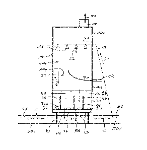
Fig. 1 shows a part of a flue gas purification with a cylindrical scrubber
tower 10. It comprises:
a flue gas entrance 12 at its lower part (end) 101 and a flue gas exit 14
above said flue gas
entrance 12, namely at its upper part 10u. The entering flue gas stream is
symbolized by arrow
Fl, while the leaving flue gas stream is characterized by arrow F2.
CA 02863846 2014-08-06
WO 2013/143788 PCT/EP2013/0534-11
13
From a channel 50, which will be described in more detail hereinafter, fresh
seawater is
pumped via a feeding pipe 16 to spray nozzles 18 arranged along a horizontal
cross section at
the upper part lOu of the scrubbing tower 10, below flue gas exit 14.
Fresh seawater is sprayed downwardly via said nozzles 18 into the flue gas
stream, which
passes the scrubbing tower 10 upwardly, i.e. in a countertlow to said seawater
droplets, which
seawater serves as an absorbent to purify the flue gas. The transport
direction towards said
nozzles 18 is shown by arrows Sl, the flow direction of the seawater
absorbent, leaving said
nozzles 18, is symbolized by arrow S2.
The strong flue gas flow entering the scrubbing tower 10 is responsible for
the seawater
absorbent being pushed ¨ at least partly - towards a part of the scrubber
tower 10 opposite to
said flue gas entrance 12. In other words: The seawater droplets being
released by said nozzles
18 all over the cross section of the scrubber tower 10 are directed on their
way downwardly
towards an area opposite flue gas entrance 14, symbolized in Fig. 1 by numeral
10p, while the
corresponding flow of seawater is characterized by arrows S3.
Seawater in the lower part 101 of the scrubbing tower 10 has passed the
absorption area,
symbolized by numeral 10a and therefore is called used seawater. It exits the
scrubbing tower
" at its lower end, i.e. the liquid exit is at a distance below its
entrance.
Below flue gas entrance 12 the scrubber tower 10 is equipped with a
distributor 20. The
distributor 20 extends over the complete inner horizontal cross-section of
said scrubber tower
so that the seawater absorbent (used seawater), when reaching the distributor
20, is stopped
by said distributor and distributed along its surface before continuing its
downwardly oriented
flow and flowing through openings (not illustrated but symbolized by arrows
54) of said
distributor 20 into a discrete basin 30 arranged below distributor 20. This
discrete basin 30
could also be arranged within the lower part 101 scrubbing tower 10, i.e. part
of it.
The distributor 20 is responsible for a more or less uniform distribution of
the used seawater
absorbent independently of its orientation on its way downwardly. It is
arranged in a moveable
way (arrows D) and is supported on vibrating bearings.
CA 02863846 2014-08-06
WO 2013/143788 PCT/EP2013/053441
14
The basin 30 collects the used seawater temporarily and aerates said used
seawater by aerators
32, arranged at a short distance to each other all over bottom area 30b.
The aeration means 32 are immerged in the liquid flowing vertically downwardly
through said
basin 30.
After this air treatment the seawater leaves the basin 30 via its permeable
bottom 34 (again
with a vertical flow direction, symbolized by arrows S5) and enters channel
50. This bottom 34
is designed correspondingly to the distributor 20 but may have any other
design. It is important
that the seawater may escape the basin 30 in the desired amount and in a
uniform manner by
corresponding openings and/or pipes (one of numerous pipes is shown by numeral
37). These
pipes 36 protrude into the liquid stream within channel 50.
The surface of the used and treated (aerated) seawater in said basin 30 is
symbolized by dotted
line 36.
The surface of the aerated seawater, now flowing horizontally within the
channel 50 (having no
upper cover), is symbolized by dotted line 56.
Channel 50 leads to post treatment arrangements for said seawater (being
optional and
therefore not illustrated further) before being directed back to the sea.
There is a continuous flow of fresh seawater along said channel 50 from a
first section 50f
before through a middle section 50b below to a second section 50s behind said
scrubbing tower
and basin 30 respectively. In the middle section 50c the aerated treated
seawater is added.
The horizontal seawater flow along channel 50 is illustrated by arrows C.
This design provides the advantage that the aeration of used seawater is
performed
homogeneously within said basin 30 and insofar with much reduced energy and
much
increased efficiency compared with prior art devices, according to which the
fresh seawater
stream is mixed with the used seawater before or during aeration. According to
the new design
the absorbent liquid is mixed with fresh seawater only after the aeration
treatment.
CA 02863846 2014-08-06
WO 2013/143788 PCDEP2013/053441
Discrete columns 40 extend between bottom 34 and distributor 20 to support the
construction.
The complete construction (scrubbing tower 10 with its basin 30) is built on
discrete
foundations 42.
Fig. 2 shows an embodiment of the gas purification device including a
distributor 20 of the
type mentioned as A above.
All parts of the device arranged above the distributor 20 arc in accordance
with the
embodiment of FIG.1 to which reference is made insofar.
The distributor 20 of Fig. 2 is made of a solid metal plate of circular shape
with an oval part
20a cut away, as shown in the top view (A-A). The total surface area of
distributor 20
corresponds to about 80% of the corresponding cross section of scrubbing tower
10 in this
area.
While the distributor 20 is fastened along its outer rim at the inner wall of
scrubbing tower 10
the oval cut 20a provides a flow through opening opposite (in Fig. 2 right) to
the main stream
(area 10p) of the liquid, thus causing the used liquid to spread along the
inclined surface of
distributor 20 before the complete volume of used liquid passes said opening
20a and flows
into collecting tank 30.
In an alternative the opening 20a may be designed as one open end of a pipe,
extending toward
the basin 30 and ending above liquid level 56 or even penetrating into the
liquid bath within
basin 30 for a very precise feeding of liquid into said basin 30.
In other words: The complete liquid stream is caused by said distributor to
enter the colleting
tank 30 in proximity to the first section 50f of channel 50.
This is decisive insofar as this allows to provide a constant/defined mixture
of used and fresh
liquid to pass the whole collecting tank 30 along the middle section 50b of
said channel 50
(beneath scrubbing tower 10) before continuing into the second section 50s of
said channel
(illustrated left in Fig. 2). This allows as well to treat this mixture of
fresh and used liquid in a
CA 02863846 2014-08-06
WO 2013/143788 PCT/EP2013/053441
16
very defined manner within said collecting tank 30 by introduction of air via
said aeration
means 32. This is symbolized in Fig. 2 by arrow P. extending over the complete
horizontal
diameter (length) of collecting tank 30.
To allow the fresh seawater in channel 50 to enter the collecting area 30 the
scrubbing tower 10
is equipped with a corresponding first lower wall section 34f which is
permeable to said liquid.
The same type of permeable wall is installed opposite to the first wall
section 34a as a second
wall section 34s permeable to said liquid.
The aerators 32 are arranged on the bottom of tank 30, which in this
embodiment corresponds
to the bottom of channel section 50b.