Note : Les descriptions sont présentées dans la langue officielle dans laquelle elles ont été soumises.
CA 02864883 2014-08-18
WO 2013/130142 PCT/US2012/067397
1
MULTISPEED DRIVE UNIT
BACKGROUND OF THE INVENTION
1. Technical Field.
[0001] The present disclosure relates to vehicle power transmission units,
and, more
particularly, to remotely-actuatable multispeed transmission units.
2. Description of the Related Art.
[0002] Large industrial machinery systems, such as earth moving equipment
and other
construction vehicles and apparatuses, may use individual power transmission
units mounted at
the system's driven endpoint. For example, gear reduction units mounted at the
hub of each
driven wheel can convert the relatively high rotational speeds of driven input
shafts into lower
rotation speeds, thereby accommodating the large-diameter wheels, heavy loads
and low speeds
frequently encountered by heavy duty construction vehicles. In another
example, independent
gear reduction units may be used in drilling devices such as earth augers, in
order to provide the
low-speed, high-torque auger rotation needed for drilling holes in tightly
packed soil.
[0003] Such individual power transmission units are sometimes referred to
as drive units,
and include a housing which encases a transmission linking an external power
source to a driven
unit. Where the power source is external (e.g., a vehicle motor and/or primary
vehicle
transmission), the drive unit may be referred to as a nonintegrated drive
unit. Alternatively,
integrated drive units include an integral power input device, such as an
attached hydraulic
motor. For example, integrated drive units may utilize a hydraulic motor which
is linked to the
drive unit via a motor output shaft coupled to an input shaft of the drive
unit. The drive unit has
its own output shaft or output hub which links to the driven unit (such as a
wheel or auger as
noted above). For the purposes of the present disclosure, "drive unit"
generically refers to both
nonintegrated and integrated drive units.
[0004] In some cases, multispeed drive units capable of shifting between
varying levels
of gear reduction may be desirable. For example, in the case of heavy duty
construction
vehicles, a drive unit having high and low gear reduction configurations may
be provided. The
high gear reduction configuration provides low-speed, high-torque power
transmission, such as
for uneven terrain at a construction site. The low gear reduction
configuration provides higher
potential wheel rotation speeds, such as for driving the vehicle on maintained
roads. In the case
SUBSTITUTE SHEET (RULE 26)
CA 02864883 2014-08-18
WO 2013/130142
PCT/US2012/067397
2
of industrial augers, the high-torque, low-speed mode (i.e., the high gear
reduction configuration)
may be used for drilling and deepening holes in the earth, while the lower-
torque, higher-speed
mode (i.e., the low-reduction configuration) may be used for quickly
extracting the auger bit
from a drilled hole and dislodging soil from the surface of the drill bit.
[0005] Substantial design efforts have focused on providing multispeed
drive units which
can be easily toggled between low and high gear reduction values. For example,
hydraulically
actuated wheel drive units may employ multiple hydraulic actuators which
operate to engage
and/or disengage internal gearing mechanisms to toggle between high- and low-
reduction
configurations (such as by toggling clutch mechanisms between engaged and
disengaged
configurations). However, such multi-actuator drive unit designs require
careful synchronization
of the various actuators to function properly, with the attendant cost and
system complexity
associated with such synchronization.
[0006] Other designs may include a mechanical shift, such as a movable or
translatable
gear which selectively engages higher or lower gear reduction assemblies
depending on the
physical location of the movable gear. However, such mechanical shift drive
units require that
the driven unit be stopped prior to toggling the movable gear, and may require
that internal
pressures on the movable gear be relieved prior to such toggling.
SUMMARY OF THE INVENTION
[0007] The present disclosure provides a multispeed drive unit which
utilizes a single
piston to toggle between multiple high and low gear reduction ratios. The
drive unit includes a
pair of clutch mechanisms, each of which acts upon a moveable ring gear of a
planetary
transmission. With the piston in a high-reduction position, one of the pair of
clutch mechanisms
engages while the other remains disengaged, such that the other planetary
transmission
components are allowed to rotate with respect to the ring gear, which is
rotationally fixed. In
this arrangement, the planetary transmission is operable to provide a high
gear reduction. When
the piston is shifted to a low-reduction position, the previously-engaged
clutch mechanism
disengages, and the previously-disengaged clutch mechanism engages. In this
arrangement, the
ring gear is free to rotate, and is fixed to the planet gear carrier of the
planetary transmission,
such that the planetary transmission provides no gear reduction.
SUBSTITUTE SHEET (RULE 26)
CA 02864883 2014-08-18
WO 2013/130142 PCT/US2012/067397
3
[0008] A drive unit utilizing a remotely actuated, single piston design in
cooperation with
a ring gear/clutch pack arrangement in accordance with the present disclosure
facilitates rapid,
in-service toggling between high and low gear reductions, while utilizing
robust, reliable and
low-cost design principles.
[0009] In one form thereof, the present disclosure provides a multispeed
drive unit
including: a rotary input positioned to be driven by a power source and
disposed at an input side
of the drive unit; a rotary output positioned to drive a driven unit and
disposed at an output side
of the drive unit; a transmission operably interposed between the rotary input
and the rotary
output, the transmission having a gear moveable between a high-reduction
configuration and a
low-reduction configuration; a first friction clutch operable to fix the gear
in the high-reduction
configuration, whereby the transmission is operable to reduce a speed of the
rotary output
relative to the rotary input when the first friction clutch is engaged; and a
second friction clutch
operable to fix the gear in the low-reduction configuration, whereby the
transmission is not
operable to reduce the speed of the rotary output relative to the rotary input
when the second
friction clutch is engaged.
[0010] In one aspect, the multispeed drive unit may further include an
actuator and a
biasing element, wherein: the gear is acted upon by the actuator which urges
the gear into one of
the first position and the opposed second position when the actuator is
actuated; and the gear is
acted upon by the biasing element which urges the gear into the other of the
first position and the
opposed second position when the actuator is not actuated.
[0011] The actuator may be configured to cause engagement of the second
friction clutch
while simultaneously allowing the first friction clutch to disengage when the
actuator is actuated;
and the biasing element is configured to cause engagement of the first
friction clutch while
simultaneously allowing the second friction clutch to disengage when the
actuator is not
actuated. The actuator may be a hydraulic actuator.
[0012] In another aspect, the gear may be moveable between a first
position toward the
input side of the drive unit and an opposed second position toward the output
side of the drive
unit, the gear in the high-reduction configuration at one of the first
position and the opposed
second position, and the gear in the low-reduction configuration at the other
of the first position
and the opposed second position.
SUBSTITUTE SHEET (RULE 26)
CA 02864883 2014-08-18
WO 2013/130142 PCT/US2012/067397
4
[0013] In yet another aspect, the first friction clutch may include a
plurality of clutch
plates frictionally engageable with one another, the plurality of clutch
plates alternately
rotationally fixed to the gear and a rotationally fixed component of the
multispeed drive unit,
such that the gear and the rotationally fixed component are rotationally fixed
to one another
when the first friction clutch is engaged such that the gear is in the high-
reduction configuration.
The rotationally fixed component may be a housing of the multispeed drive unit
interposed
between the input side and the output side.
[0014] In still another aspect, the second friction clutch may include a
plurality of clutch
plates frictionally engageable with one another, the plurality of clutch
plates alternately
rotationally fixed to the gear and a component of the transmission, such that
the gear and the
transmission are rotationally fixed to one another when the second friction
clutch is engaged
such that the gear is in the low-reduction configuration.
[0015] In yet another aspect, the transmission is a planetary transmission
assembly
including: a sun gear having sun gear teeth formed on an outer surface
thereof; at least one planet
gear having planet gear teeth formed on an outer surface of the planet gear,
the planet gear teeth
intermeshingly engaged with the sun gear teeth such that rotation of the sun
gear is capable of
rotating the at least one planet gear; a planet gear carrier rotatably
supporting the at least one
planet gear, such that the at least one planet gear is independently rotatable
with respect to the
planet gear carrier; and the gear moveable between a high-reduction
configuration and a low-
reduction configuration including a ring gear having ring gear teeth formed on
an inner surface
of the ring gear, the ring gear teeth intermeshingly engaged with the planet
gear teeth, the planet
gear disposed between the ring gear and the sun gear such that torque is
transmissible from the
sun gear to the planet gear carrier via the planet gear.
[0016] The ring gear may be rotationally secured to the planet gear
carrier when in the
low-reduction configuration. The drive unit may include a rotationally fixed
housing interposed
between the input side and the output side, the ring gear rotationally secured
to said housing
when said ring gear is in said high-reduction configuration.
[0017] In yet another aspect, the rotary output may rotate at the same
speed as the rotary
input when the gear is in the low-reduction configuration. For example, the
rotary input may
rotate at between 2 and 10 times faster than the rotary output when the gear
is in the high-
reduction configuration.
SUBSTITUTE SHEET (RULE 26)
CA 02864883 2014-08-18
WO 2013/130142
PCT/US2012/067397
[0018] In another form thereof, the present disclosure provides a
multispeed drive unit
including: a rotary input positioned to be driven by a power source and
disposed at an input side
of the drive unit; a rotary output positioned to drive a driven unit and
disposed at an output side
of the drive unit; a planetary transmission assembly operably interposed
between the rotary input
and the rotary output, the planetary transmission assembly including: a sun
gear having sun gear
teeth formed on an outer surface thereof; at least one planet gear having
planet gear teeth formed
on an outer surface of the planet gear, the planet gear teeth intermeshingly
engageable with the
sun gear teeth such that rotation of the sun gear is capable of rotating the
at least one planet gear;
a planet gear carrier rotatably supporting the at least one planet gear, such
that the at least one
planet gear is independently rotatable with respect to the planet gear
carrier; and a ring gear
having ring gear teeth formed on an inner surface of the ring gear, the ring
gear teeth
intermeshingly engageable with the planet gear teeth, the planet gear disposed
between the ring
gear and the sun gear such that torque is transmissible from the sun gear to
the planet gear carrier
via the planet gear, the ring gear selectively configurable into a high-
reduction configuration and
a low-reduction configuration by moving the ring gear toward one of the input
side of the drive
unit and the output side of the drive unit; a housing interposed between the
input side and the
output side, the housing stationary with respect to the planetary transmission
assembly; a first
clutch pack including: a first clutch plate rotatably fixed to an outer
surface of the ring gear; and
a second clutch plate rotatably fixed to an inner surface of the housing, the
second clutch plate
engageable with the first clutch plate to rotatably fix the ring gear to the
housing when the ring
gear is in the high-reduction configuration, the planetary transmission
assembly operable to
reduce a speed of the rotary output relative to the rotary input when the
first and second clutch
plates are engaged; and a second clutch pack including: a third clutch plate
rotatably fixed to the
inner surface of the ring gear; and a fourth clutch plate rotatably fixed to
the planet gear carrier,
the third clutch plate engageable with the fourth clutch plate to rotatably
fix the ring gear to the
planet gear carrier when the ring gear is in the low-reduction configuration,
the planetary
transmission assembly rotating as a single unit when the third and fourth
clutch plates are
engaged.
[0019] In one aspect, the multispeed drive unit further may further
include: a biasing
element urging the first and second clutch plates into engagement with one
another, whereby the
biasing element urges the ring gear into the high-reduction configuration; and
a gearshift piston
SUBSTITUTE SHEET (RULE 26)
CA 02864883 2014-08-18
WO 2013/130142
PCT/US2012/067397
6
moveable between an actuated position and a non-actuated position, the
gearshift piston allowing
the first and second clutch plates to engage when in the non-actuated
position, the gearshift
piston urging the second clutch pack into engagement when in the actuated
position, whereby the
gearshift piston cooperates to toggle the ring gear between the high-reduction
configuration and
the-low reduction configuration.
[0020] The multispeed drive unit may further include a fluid inlet leading
to a fluid
chamber, the gearshift piston urged into the actuated position when
pressurized fluid is received
in the fluid chamber. The biasing element may act on the ring gear such that a
shoulder of the
ring gear is positioned to abut one of the first clutch plate and the second
clutch plate to engage
with the other of the first clutch plate and the second clutch plate when the
gearshift piston is in
the non-actuated position.
[0021] In another aspect, the multispeed drive unit may further include a
low-friction
interface between one of the third and fourth clutch plates and the gearshift
piston, whereby
rotation therebetween is facilitated when the second clutch pack is engaged.
The first clutch
pack may be disposed radially outwardly of the second clutch pack, whereby the
first clutch pack
is an outer clutch pack and the second clutch pack is an inner clutch pack.
[0022] In yet another aspect, the at least one planet gear may
circumnavigate the sun gear
when the ring gear is in the high-reduction configuration, and the ring gear
may rotate at the
same speed as with the sun gear when the ring gear is in the low-reduction
configuration.
[0023] In yet another form thereof, the present disclosure provides a
multispeed drive
unit including: input means for receiving power from a power source, the input
means disposed
at an input side of the drive unit; output means for driving a driven unit,
the output means
disposed at an output side of the drive unit; transmission means for
selectively toggling between
a high-reduction configuration and a low-reduction configuration, the
transmission means
including a moveable gear interposed between the input means and the output
means; means for
fixing the moveable gear in the high-reduction configuration during operation
of the multispeed
drive unit, such that the transmission means is operable to reduce a speed of
the output means
relative to the input means; and means for fixing the moveable gear in the low-
reduction
configuration during operation of the multispeed drive unit, such that the
transmission means is
not operable to reduce the speed of the output means relative to the input
means.
SUBSTITUTE SHEET (RULE 26)
CA 02864883 2014-08-18
WO 2013/130142 PCT/US2012/067397
7
[0024] For example, the input means for receiving power may be an input
shaft such as
input shaft 27 shown in Fig. 2A, or may be an input gear such as sun gear 26
shown in Fig. 2A.
Moreover, it is contemplated that any rotary input may be used to transmit
power to a multispeed
drive unit made in accordance with the present disclosure, as required or
desired for a particular
application. Moreover, it is contemplated that any rotary input may be used to
transmit power to
a multispeed drive unit made in accordance with the present disclosure, as
required or desired for
a particular application.
[0025] The output means for receiving power may be an output shaft such as
output shaft
28 shown in Fig. 2A, or may be the output component of a planetary reduction
mechanism. In
the context of drive unit 10 described below, the output component of the
illustrated planetary
reduction mechanism is planet gear carrier 22, which is in turn rotationally
fixed to output shaft
28. Moreover, it is contemplated that any rotary output may be used to drive a
driven unit in
accordance with the present disclosure, as required or desired for a
particular application.
[0026] Transmission means for selectively toggling between a high-
reduction
configuration and a low-reduction configuration of the transmission means may
be a planetary
transmission arrangement, such as the planetary transmission of drive unit 10
including ring gear
20, gear carrier 22, planet gears 24 and sun gear 28 (as described in further
detail below). In this
exemplary embodiment, the selective toggling functionality of the transmission
is provided by
the axial movement (i.e., toward the input and/or output sides of drive unit
10) of ring gear 20,
which engages or bypasses the gear-reduction functionality of the planetary
system as described
below.
[0027] Means for fixing the gear in a high-reduction configuration during
operation of
the multispeed drive may be outer clutch pack 40, which is operable to
rotationally fix ring gear
20 to stationary housing 18 (Fig. 2A) as described below. When clutch pack 40
is engaged, ring
gear 20 is effectively fixed with respect to the other stationary components
of wheel drive 10,
such that the other components of the planetary transmission system rotate
within, and with
respect to, ring gear 20. When these planetary components are allowed to so
rotate, the planetary
transmission operates to reduce the speed of output shaft 28 with respect to
input shaft 27.
[0028] Means for fixing the gear in the low-reduction configuration during
operation of
the multispeed drive may be inner clutch pack 60, which is operable to
rotationally fix ring gear
20 to planet gear carrier 22 (Fig. 3A) as described below. When clutch pack 40
is engaged, ring
SUBSTITUTE SHEET (RULE 26)
CA 02864883 2014-08-18
WO 2013/130142 PCT/US2012/067397
8
gear 20 is effectively constrained to rotate together with the other
components of the planetary
transmission system, including sun gear 26 and planet gear carrier 22. When
these planetary
components rotationally fixed to one another in this fashion, the planetary
transmission does not
operates to reduce the speed of output shaft 28 with respect to input shaft
27, instead directly
transmitting torque from input shaft 27 (Fig. 2A) to output shaft 28.
[0029] In one aspect, the multispeed drive may include a biasing means for
biasing the
gear into one of the high-reduction configuration and the low-reduction
configuration; and
hydraulic means for selectively urging the moveable gear into the other of the
high-reduction
configuration and the low-reduction configuration, the hydraulic means
operating against a
biasing force provided by the biasing means.
[0030] For example, biasing means for biasing the gear may be springs 34,
which bias
ring gear 20 toward a high-reduction configuration as described in detail
below. Hydraulic
means for selectively urging ring gear 20 into the low-reduction configuration
may be gearshift
piston 12, which can move ring gear 20 toward the input side of drive unit 10
by filling fluid
chamber 56 with pressurized fluid. As described in detail below, this
pressurized fluid can be of
sufficient pressure to overcome the opposing biasing force provided by springs
34.
[0031] In another aspect, the means for fixing the moveable gear in the
high-reduction
configuration and the means for fixing the moveable gear in the low-reduction
configuration may
each include means for frictionally rotationally fixing one component to
another.
[0032] For example, outer and inner clutch packs 40, 60 (discussed above
and described
in detail below) may each be formed from a plurality of clutch plates 42, 44
and 62, 64
respectively. When plates 42, 44 or plates 62, 64 are urged into contact with
one another,
frictional interaction at the contact interface causes clutch pack 40 or 60 to
effectively
rotationally fix the plates to one another, and therefore to rotationally fix
the components
engaged by the plates to one another. In the case of outer clutch pack 40,
clutch plates 42, 44 are
rotationally fixed to stationary housing 18 and ring gear 20, respectively,
which causes ring gear
20 to be rotationally fixed to housing 18 when plates 42, 44 are frictionally
engaged. In the case
of inner clutch pack 60, clutch plates 62, 64 are rotationally fixed to ring
gear 20 and planet gear
carrier 22, respectively, which causes ring gear 20 to be rotationally fixed
to planet gear carrier
22 when plates 62, 64 are frictionally engaged.
SUBSTITUTE SHEET (RULE 26)
CA 02864883 2014-08-18
WO 2013/130142 PCT/US2012/067397
9
BRIEF DESCRIPTION OF THE DRAWINGS
[0033] The above mentioned and other features and advantages of the
present disclosure,
and the manner of attaining them, will become more apparent and the invention
itself will be
better understood by reference to the following description of an embodiment
of the invention
taken in conjunction with the accompanying drawings, wherein:
[0034] Fig. 1A is an input-end, elevation view of a drive unit in
accordance with the
present disclosure;
[0035] Fig. 1B is an input-end, elevation, partial section view of the
drive unit shown in
Fig. 1A, taken along line 1B-1B of Fig. 1A;
[0036] Fig. 2A is a side, elevation, partial section view of the drive
unit shown in Fig.
1B, in which a gearshift piston is shown in a non-actuated position;
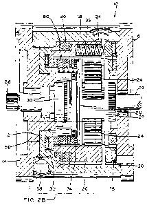
[0037] Fig. 2B is an enlarged view of a portion of Fig. 2A, illustrating
the non-actuated
gearshift piston and associated clutch pack configurations corresponding to a
high gear reduction
configuration of the drive unit;
[0038] Fig. 2C is a perspective, partial section view of the drive unit
shown in Fig. 2A,
taken from the input end thereof;
[0039] Fig. 2D is a perspective, partial section view of the drive unit
shown in Fig. 2A,
taken from the output end thereof;
[0040] Fig. 3A is an elevation, partial section view of the drive unit
shown in Fig. 2A, in
which the gearshift piston of Fig. 2A has been toggled to an actuated
position;
[0041] Fig. 3B is an enlarged view of a portion of the drive unit shown in
Fig. 3A,
illustrating the actuated gearshift piston and associated clutch pack
configurations corresponding
to a low gear reduction configuration of the drive unit;
[0042] Fig. 3C is a perspective, partial section view of the drive unit
shown in Fig. 3A,
taken from the input end thereof;
[0043] Fig. 3D is a perspective, partial section view of the drive unit
shown in Fig. 3A,
taken from the output end thereof;
[0044] Fig. 4A is a perspective view of an outer clutch pack made in
accordance with the
present disclosure, taken from the input end thereof;
SUBSTITUTE SHEET (RULE 26)
CA 02864883 2014-08-18
WO 2013/130142
PCT/US2012/067397
[0045] Fig. 4B is a perspective view of the outer clutch pack shown in
Fig. 4A, taken
from the output end thereof, and illustrating the outer clutch pack mounted to
a ring gear made in
accordance with the present disclosure;
[0046] Fig. 4C is another perspective view of the outer clutch pack shown
in Fig. 4A,
illustrating the outer clutch pack mounted within a gearbox housing made in
accordance with the
present disclosure;
[0047] Fig. 4D is another perspective view of the outer clutch pack and
gearbox housing
of Fig. 4C, shown with the ring gear of Fig. 4B coupled thereto, in which a
portion of the ring
gear is shown broken away for clarity;
[0048] Fig. 5A is a perspective view of an inner clutch pack made in
accordance with the
present disclosure, taken from the output end thereof;
[0049] Fig. 5B is another perspective view of the inner clutch pack shown
in Fig. 5A, in
which the inner clutch pack is shown assembled to the ring gear shown in Figs.
4B and 4D, and
to a gear carrier made in accordance with the present disclosure;
[0050] Fig. 6 is a perspective, partial section view of the drive unit
shown in Fig. 1B,
taken from the input end thereof, in which the input hub of the drive unit has
been removed to
illustrate internal components of the drive unit; and
[0051] Fig. 7 is a perspective, partial section view of the drive unit
shown in Fig. 1B,
taken from the output end thereof, in which the output hub of the drive unit
has been removed to
illustrate internal components of the drive unit;
[0052] Corresponding reference characters indicate corresponding parts
throughout the
several views. The exemplification set out herein illustrates an exemplary
embodiment of the
invention, and such exemplification is not to be construed as limiting the
scope of the invention
in any manner.
DETAILED DESCRIPTION OF THE PRESENT INVENTION
[0053] The present disclosure provides two-speed drive unit 10 which
toggles between
two differing levels of gear reduction by actuation of a single gearshift
piston 12. As described
in detail below, gearshift piston 12 toggles between a high-reduction position
(Figs. 2A-2D) and
a low-reduction position (Figs. 3A-3D). In the high-reduction position,
gearshift piston 12
causes outer clutch pack 40 to become operably engaged, thereby allowing a
planetary gear
SUBSTITUTE SHEET (RULE 26)
CA 02864883 2014-08-18
WO 2013/130142 PCT/US2012/067397
11
system to operate inside drive unit 10 to provide a high gear reduction, i.e.,
output shaft 28
rotates substantially slower than input shaft 27 (Fig. 2A) coupled to the
input sun gear 26. In the
low-reduction position, gearshift piston 12 allows outer clutch pack 40 to
become disengaged
and causes clutch pack 60 to become operably engaged, thereby neutralizing the
gear reduction
functionality of the planetary gear system. Thus, in the low-reduction
configuration, drive unit
provides no gear reduction, i.e., output shaft 28 rotates at the same speed as
input shaft 27
(Fig. 2A) coupled to the input sun gear 26.
[0054] Turning now to Fig. 2A, drive unit 10 is shown in a cutaway,
partial section view.
The section of Fig. 2A is taken along line 1B-1B of Fig. 1A, but shows non-
sectioned views of
output shaft 28, bearings 30 and the components of a planetary transmission
system including
sun gear 26, planet gears 24 and planet gear carrier 22. Ring gear 20, which
also participates in
the operation of the planetary gear reduction system as described below, is
shown in section.
Several of the non-sectioned components in the view of Fig. 2A are shown
protruding from the
otherwise sectioned components of Fig. 1B.
[0055] Drive unit 10 includes input-side hub 16 and output-side hub 14
having gear box
housing 18 disposed therebetween. Hubs 14, 16 and housing 18 are all affixed
to one another,
such as by housing bolts 36 (Figs. lA and 1B) passing through appropriately
sized apertures A
formed in output hub 14, input hub 16 and gear box housing 18 (Figs. 2D, lA
and 4D,
respectively). Output hub 14 mounts to a vehicle frame (not shown), secondary
reduction box
(not shown) or other mounting surface which is stationary with respect to the
rotating driven unit
(e.g., a vehicle wheel or auger drill bit) which receives power via drive unit
10. Input hub 16
may also be mounted to a vehicle frame member, adjacent to input shaft 27
(Fig. 2A) which is
rotatably coupled to sun gear 26 and drives the driven unit.
[0056] For purposes of the present disclosure, input hub 16 is considered
to be at an
"input side" of drive unit 10, in that sun gear 26 receives power from an
external or integral
power source, such as a primary vehicle transmission, motor output shaft or
the like.
Conversely, output hub 14 is considered to be mounted at an "output side" of
drive unit 10, in
that power output is provided to a driven unit via output shaft 28 which is
disposed just internally
of output hub 14. As noted above, input shaft 27 may pass into the central
aperture of input hub
16 to drivingly engage with the internal splines formed along the inner bore
wall of sun gear 26.
SUBSTITUTE SHEET (RULE 26)
CA 02864883 2014-08-18
WO 2013/130142 PCT/US2012/067397
12
[0057] Power is transmitted from input sun gear 26 to output shaft 28 via
a planetary
transmission assembly, as shown in Fig. 2A. As described in detail below,
drive unit 10 can
selectively engage and disengage the planetary transmission assembly to
provide a variable gear
reduction. When the planetary transmission assembly is engaged and operating,
input sun gear
26 drives output shaft 28 via the gear reduction mechanism of the planetary
transmission
assembly.
[0058] More particularly, planet gear carrier 22 directly drives rotation
of output shaft 28
by being rotatably fixed therewith, such as via a geared shaft end in
intermeshed engagement
with internal gear teeth of planet gear carrier 22 as shown in Figs. 2A and
2D. Planet gear
carrier 22 is rotatably coupled with each of a plurality of planet gears 24,
such as three planet
gears 24 as shown in the drawings, such that planet gears 24 can rotate about
their respective
gear axles independently of gear carrier 22. In the illustrated embodiment,
pins 72 provide the
axles for this independent rotation. The outer gear teeth of planet gears 24
are intermeshed with
both inner gear teeth of ring gear 20 (near the outer periphery of gear
carrier 22) and with outer
gear teeth of sun gear 26 (disposed within the central bore of gear carrier
22).
[0059] When the planetary transmission assembly is operational (i.e., when
drive unit 10
is in the high-reduction configuration as described below), ring gear 20 is
fixed with respect to
gear box housing 18 (also described in detail below) and therefore may be
considered to be
"stationary" in the context of drive unit 10. Therefore, as sun gear 26
rotates under the influence
of the external or integral power source, planet gears 24 circumnavigate sun
gear 26 while the
gear teeth of planet gears 24 remain in intermeshing engagement with both ring
gear 20 and sun
gear 26, in turn causing gear carrier 22 to also rotate. As planet gears 24
circumnavigate sun
gear 26, gear carrier 22 rotates at a slower rotational speed than the
rotational speed of input sun
gear 26, thereby driving output shaft 28 at the same reduced rotational output
speed. In an
exemplary embodiment, for example, the rotational speed of input sun gear 26
may be between 2
and 10 times faster than the corresponding rotational speed of output shaft
28.
[0060] As noted above, drive unit 10 can be toggled between high-reduction
and low-
reduction configurations by selectively engaging one of outer and inner clutch
packs 40, 60.
Clutch packs 40, 60 are referred to herein as "outer" and "inner" clutch pack
owing to their
relative radial locations, i.e., radially outward or radially inward.
Selective engagement of clutch
SUBSTITUTE SHEET (RULE 26)
CA 02864883 2014-08-18
WO 2013/130142 PCT/US2012/067397
13
packs 40, 60 is accomplished by selectively pressurizing or depressurizing
fluid chamber 56, as
described in detail below.
[0061] Turning to Figs. 2A-2D, drive unit 10 is shown in a high-reduction
configuration,
in which inner clutch pack 60 is disengaged and outer clutch pack 40 is
engaged. The high-
reduction configuration results from a lack of sufficiently pressurized fluid
within fluid chamber
56 (Figs. 2A and 2B), which allows springs 34 to bias ring gear 20 toward the
output side of
drive unit 10, i.e., toward the left as shown Figs. 2A through 2D. More
particularly, referring to
Fig. 2B, ring gear 20 includes shoulder 21A positioned to abut thrust bearing
32 contained within
gearshift piston 12. Thrust bearing 32 also abuts inner clutch plate 62
disposed at the output side
of inner clutch pack 60, thereby serving to engage inner clutch pack 60 as
described in detail
below with respect to the low-reduction configuration of drive unit 10.
[0062] In the high-reduction configuration of Fig. 2B, clutch relief space
74 is made
available to allow inner clutch plates 62, 64 of inner clutch pack 60 to
spread apart from one
another in the space between thrust bearing 32 and gear carrier 22. The
spreading apart of clutch
plates 62, 64 prevents substantial frictional interaction therebetween,
thereby rendering inner
clutch pack 60 disengaged.
[0063] Meanwhile, shoulder 21B of ring gear 20 abuts clutch plate 44
disposed at the
input side of clutch pack 40. The leftward bias of ring gear 20 provided by
springs 34 (Fig. 2A)
creates pressure on and between clutch plates 42, 44 of outer clutch pack 40,
squeezing plates 42,
44 together between shoulder 21B of ring gear 20 and shoulder 19 of gear box
housing 18. This
squeezing action provided by springs 34 occurs when fluid chamber 56 is not
significantly
pressurized, as described below, thereby allowing springs 34 to forcefully
urge clutch plates 42,
44 toward one another. When so squeezed, frictional interaction between clutch
plates 42, 44
causes clutch plates 42, 44 to be effectively rotationally fixed to one
another, thereby placing
outer clutch pack 40 into an engaged configuration in which clutch pack 40
rotationally fixes
ring gear 20 to housing 18. As described in detail below, this torque
transmission effectively
rotationally immobilizes ring gear 20 and enables the planetary transmission
system to operate as
a gear-reducing unit.
[0064] Outer clutch pack 40 is shown isolated from the remainder of drive
unit 10 in Fig.
4A. As illustrated, outer clutch pack 40 includes a plurality of alternating
clutch plates 42, 44,
though it is appreciated that any number of clutch plates 42, 44 could be used
(including a single
SUBSTITUTE SHEET (RULE 26)
CA 02864883 2014-08-18
WO 2013/130142 PCT/US2012/067397
14
pair). Clutch plates 42, 44 are made of materials which have a high frictional
interaction with
one another, thereby enabling large transfers of torque therebetween when the
plates are
squeezed together as described above.
[0065] Clutch plates 42 include outer lugs 46 sized to be received within
corresponding
recesses 50 formed in an inner surface of gear box housing 18 (Figs. 2B and
4C). As shown in
Fig. 4C, clutch plates 42 are rotationally fixed with respect to gear box
housing 18 when
assembled thereto by interaction between outer lugs 46 and recesses 50.
Similarly, as best seen
in Fig. 4B, clutch plates 44 include inner lugs 48 sized to be received within
recesses 52 formed
in an outer surface of ring gear 20. Thus, outer clutch plates 44 are
rotationally fixed with
respect to ring gear 20 when assembled thereto by interaction between inner
lugs 48 and recesses
52.
[0066] As illustrated in Figs. 2B and 4D, clutch plates 42,44 of outer
clutch pack 40 are
disposed between ring gear 20 and gear box housing 18 upon assembly. When ring
gear 20 is
allowed to be biased toward the output side of drive unit 10 by the biasing
force provided by
springs 34, the frictional interaction between clutch plates 42, 44
rotationally fixes ring gear 20
to gear box housing 18. In effect, this rotational fixation renders ring gear
20 stationary with
respect to the other movable parts of drive unit 10, including the other parts
of the planetary
transmission assembly. Conversely, as described in detail below, movement of
ring gear 20
toward the input side (i.e., toward the right as illustrated in the figures)
creates space between
respective pairs of clutch plates 42, 44, thereby freeing ring gear 20 to
rotate with respect to gear
box housing 18.
[0067] When outer clutch pack 40 in engaged and ring gear 20 is
stationary, the planetary
transmission mechanism operates to create gear reduction between input sun
gear 26 and output
shaft 28, as noted above. More particularly, torque transmission from sun gear
26 to output shaft
28 occurs via the planetary transmission system, which effects the gear
reduction by the
independent rotation of planet gears 24 and their attendant circumnavigation
around sun gear 26,
as described above.
[0068] Therefore, drive unit 10 provides a high gear reduction when fluid
chamber 56 is
non-pressurized, such that springs 34 engage outer clutch pack 40 and
immobilize ring gear 20,
in turn enabling the planetary transmission system to function as a gear
reducing unit.
SUBSTITUTE SHEET (RULE 26)
CA 02864883 2014-08-18
WO 2013/130142
PCT/US2012/067397
[0069] By contrast, drive unit 10 is shown in a low-reduction
configuration in Figs. 3A-
3D. To configure drive unit 10 into the low-reduction configuration,
pressurized fluid is
delivered to fluid chamber 56 via fluid inlet 58, which urges gearshift piston
12 and thrust
bearing 32 toward the input end of drive unit 10 (i.e., to the right as shown
in the Figs. 3A-3D).
As best seen in Fig. 3B, thrust bearing 32 is positioned to contact both ring
gear 20 and inner
clutch pack 60, while both gearshift piston 12 and thrust bearing 32 remain
spaced away from
outer clutch pack 40. As described below, this configuration allows
simultaneous engagement of
inner clutch pack 60 and disengagement of outer clutch pack 40.
[0070] When sufficient fluid pressure builds up within chamber 56, the
force on gearshift
piston 12 causes thrust bearing 32 to overcome the biasing force of springs 34
and shift ring gear
toward the input end of drive unit 10 while compressing springs 34. As ring
gear 20 moves,
clutch relief space 54 (Figs. 3A and 3B) opens up between shoulder 21B of ring
gear 20 and
shoulder 19 of gear box housing 18. Clutch relief space 54 allows outer clutch
plates 42, 44 to
spread apart from one another, thereby rotationally decoupling ring gear 20
from gear box
housing 18. Thus, ring gear 20 becomes free to rotate with respect to gear box
housing 18. In an
exemplary embodiment, the number and spring rates of springs 34 are chosen
such that clutch
relief space 54 begins to open upon application of 200 pounds per square inch
(psi) of pressure
within fluid chamber 56. The fluid utilized for creating this pressure may be
hydraulic fluid, for
example. In the illustrative embodiment shown in Fig. 4D, for example, twenty
blind bores 35
are formed in ring gear 20 to receive and capture twenty springs 34 (it being
understood that six
of the twenty bores are not shown in the broken-away portion of ring gear 20).
[0071] As noted above, thrust bearing 32 acts on both ring gear 20 and
inner clutch pack
60, so that as clutch relief space 54 opens, clutch relief space 74 between
gear carrier 22 and
thrust bearing 32 (Figs. 2A and 2B) closes. Thus, the alternating inner clutch
plates 62, 64 of
inner clutch pack 60 become squeezed between thrust bearing 32 and shoulder 23
of gear carrier
22. Thus, as fluid pressure increases within chamber 56, clutch plates 62, 64
are squeezed
together with increasing force, thereby increasing the frictional interaction
between plates 62, 64
such that inner clutch pack 60 rotates as a single unit as torque is
transferred across clutch plates
62, 64. Thrust bearing 32 provides a low-friction interface between the output-
side clutch plate
62 of inner clutch pack 60 and piston 12, to facilitate rotation therebetween
when clutch pack 60
is engaged. At the input-side surfaces of ring gear 20 and gear carrier 22,
outer and inner input-
SUBSTITUTE SHEET (RULE 26)
CA 02864883 2014-08-18
WO 2013/130142 PCT/US2012/067397
16
side thrust bearings 78, 76 (Fig. 6) may be provided to facilitate smooth
rotation in a similar
fashion.
[0072] Turning to Fig. 5A, inner clutch pack 60 is shown isolated from the
remainder of
drive unit 10. As illustrated, clutch plates 62 each include a plurality of
gear teeth 66 protruding
radially outwardly from the outer periphery clutch plates 62. As shown in Fig.
5B, gear teeth 66
engage correspondingly shaped gear teeth formed in the inner bore of ring gear
20, thereby
rotationally fixing inner clutch plates 62 to ring gear 20 upon assembly.
Similarly, inner clutch
plates 64 include recesses 68 protruding radially outwardly from the inner
periphery thereof. As
shown in Fig. 5B, recesses 68 of clutch plates 64 are alignable with
corresponding recesses 70
protruding radially inwardly from the outer periphery of gear carrier 22, such
that coupling pins
72 may be inserted into each adjacent pair of recesses 68, 70 to rotationally
fix inner clutch
plates 64 to gear carrier 22 as illustrated in Fig. 5B.
[0073] When inner clutch pack 60 is in an engaged configuration as shown
in Figs. 3A
and 3B, the frictional interaction between clutch plates 62, 64 transfers
torque from ring gear 20
(free to rotate with respect to gearbox housing 18, owing to the creation of
clutch relief space 54
as noted above) to gear carrier 22 (which directly drives output shaft 28 as
noted above). Thus,
when sufficient pressure is applied to inner clutch pack 60 to squeeze clutch
plates 62, 64
together, gear carrier 22 becomes rotationally fixed to ring gear 20 such that
gear carrier 22 and
ring gear 20 both rotate at the speed of input sun gear 26.
[0074] When in the low-reduction configuration of Figs. 3A-3D, sun gear 26
also rotates
at the same speed as output shaft 28, rather than rotating faster as is the
case in the high-
reduction configuration described above. In effect, the planetary transmission
system ceases to
operate as a gear reduction unit and instead serves to transmit torque from
sun gear 26 to output
shaft 28 without gear reduction. More particularly, the common rotation of
ring gear 20 and gear
carrier 22 prevents rotation of planet gears 24 about their respective pins
72, because such
rotation requires relative rotation of gear carrier 22 with respect to ring
gear 20. Thus,
engagement of inner clutch pack 60 (and the concomitant rotational fixation of
ring gear 20 to
gear carrier 22) converts planet gears 24 from their circumnavigating, gear-
reducing function
(described above) into direct transmitters of torque from sun gear 26 to ring
gear 20.
[0075] Stated another way, planet gears 24 cease to circumnavigate sun
gear 26 when
gear carrier 22 is rotationally fixed to ring gear 20. Instead, planet gears
24 remain rotationally
SUBSTITUTE SHEET (RULE 26)
CA 02864883 2014-08-18
WO 2013/130142 PCT/US2012/067397
17
fixed with respect to sun gear 26 by virtue of the engagement of intermeshing
gear teeth between
the outer gear teeth of planet gears 24 and the adjacent outer and inner gear
teeth of sun gear 26
and ring gear 20 respectively. Thus ring gear 20, gear carrier 22, planet
gears 24 and sun gear 26
remain statically engaged with one another, all rotating as a single unit
under the influence of
power transmitted thereto from sun gear 26. In this way, engagement of inner
clutch pack 60
(and the concomitant disengagement of outer clutch pack 40) effectively
converts drive unit 10
from a high reduction transmission unit into a 1:1 transmission with no gear
reduction.
[00761 As noted above, the amount of fluid pressure within fluid chamber
56 dictates the
amount of torque transmissible through inner clutch pack 60, because increased
fluid pressure
squeezes plates 62, 64 together with greater force and thereby increases the
frictional interaction
therebetween. In the exemplary embodiment described above in which fluid
pressure of 200 psi
causes gearshift piston 12 to overcome the biasing force of springs 34 and
begin to move, an
additional pressure of between 200 psi and 500 psi applied within fluid
chamber 56 (for a total of
400-700 psi) may be applied to ensure firm engagement of inner clutch pack 60
and avoid
slippage between adjacent pairs of clutch plates 62, 64.
100771 Thus, drive unit 10 provides a single-piston, hydraulically
actuated two speed
transmission. However, it is contemplated that certain modifications may be
made to the
exemplary embodiment shown in the appended figures and described above, while
remaining
within the scope of the present disclosure. For example, gearshift piston 12
may be
mechanically actuated rather than fluid-powered. More than two discreet gear
reductions may be
provided by utilizing additional iterations of the single piston design within
a common drive unit.
[0078] The present single piston design, utilizing movement of a single
monolithic part
(namely, ring gear 20) in order to effect a change in gear reduction, allows a
change in gear
reductions to be made remotely and/or automatically. Further, the single-
piston design provides
this remote-operable, multi-speed functionality with minimal of cost and
complexity in the drive
unit and its surrounding infrastructure.
[0079] Moreover, a single piston design in accordance with the present
disclosure may be
considered a functionally "binary" system, in that the system defines only two
potential states.
In the "on" or actuated state, gearshift piston 12 overcomes the biasing force
of springs 34 to
provide low gear reduction and a relatively higher output speed, as described
in detail above. In
the "off' or non-actuated state, gearshift piston 12 is functionally absent
from the operation of
SUBSTITUTE SHEET (RULE 26)
CA 02864883 2014-08-18
WO 2013/130142
PCT/US2012/067397
18
drive unit 10, and springs 34 are allowed to configure drive unit 10 into a
high-reduction
arrangement for a relatively lower output speed of output shaft 28.
[0080] Advantageously, this binary operation of drive unit 10 allows
gearshift piston 12
to be toggled remotely using a minimum of fluid power control devices, such as
a single on/off
solenoid which selectively injects pressurized fluid into chamber 56 via fluid
inlet 58. Further,
the use of outer and inner clutch packs 40, 60 facilitates toggling of drive
unit 10 between high-
reduction and low-reduction configurations without pausing the operation of
drive unit 10. To
accommodate this "shift on the fly" functionality, clutch plates 42, 44, 62,
64 may be adapted to
allow limited slippage therebetween during the shifting process. For example,
outer and inner
clutch packs 40, 60 may be of a "wet clutch" design which bathes clutch plates
42, 44, 62, 64 in
lubricating fluid to facilitate repeated, limited slipping as drive unit 10 is
shifted between high-
reduction and low-reduction configurations without disrupting the application
of power to output
shaft 28. To facilitate this "wet clutch" functionality, transmission fluid
may be introduced into
the drive unit 10 via fluid port 38 formed in input hub 16 (Figs lA and 1B).
[0081] While this invention has been described as having an exemplary
design, the
present invention can be further modified within the spirit and scope of this
disclosure. This
application is therefore intended to cover any variations, uses, or
adaptations of the invention
using its general principles. Further, this application is intended to cover
such departures from
the present disclosure as come within known or customary practice in the art
to which this
invention pertains and which fall within the limits of the appended claims.
SUBSTITUTE SHEET (RULE 26)