Note : Les descriptions sont présentées dans la langue officielle dans laquelle elles ont été soumises.
CA 02864939 2014-08-19
WO 2013/123602
PCT/CA2013/050138
APPARATUS FOR DELIVERING DRILL PIPE TO A DRILL RIG
Field of the Invention
The present invention is directed to an apparatus for delivering lengths of
drill pipe to a drill
rig. In particular, the apparatus is suited to moving drill pipe to and from
the rig floor of a
drilling rig, in an automated manner.
Background of the Invention
On drilling rigs, drill pipe is raised from the ground to the rig floor, and
conversely lowered
from the rig floor to the ground by means of a catwalk and slide. A catwalk
typically consists
of a long, rectangular platform usually made of steel that is located at the
bottom of the slide
and oriented perpendicularly to the V-door. The catwalk platform is used as a
staging area for
drill pipe that is about to be lifted to the rig floor, or which has been
lowered from the rig
floor. The slide is an inclined plane below the V-door that connects the rig
floor to the
catwalk. It is frequently a reinforced steel plate with a central groove,
which acts as a guide
when pipes are dragged or pushed to and from the rig floor.
There are a number of mechanized systems designed to lift or push drill pipe
along the
catwalk to the slide and up to the V-door. A commonly used conventional system
uses a skate
that pushes the pipe along the catwalk and up the inclined slide. However, the
skate delivers
the drill pipe to the rig floor in an uncontrolled and projectile-like manner
posing a safety risk
to those working in proximity to the V-door. Furthermore, a significant amount
of force is
required to overcome frictional and gravitational forces when the drill pipe
is pushed up the
slide in the conventional system. Also, the steepness of the slide in the
conventional system
poses a significant risk when used for access by workers. Conventional
delivery systems are
also restricted to the delivery of drill pipe and occasionally, lighter rig
equipment such as
slips. Further still, many conventional systems can deliver only one drill
pipe per delivery
cycle.
What is needed is an apparatus for delivering a drill pipe between the ground
and a rig floor
that mitigates the limitations of a conventional catwalk and slide system.
Summary of the Invention
In one aspect, the present invention provides an apparatus for delivering a
drill pipe to a drill
1
CA 02864939 2014-08-19
WO 2013/123602
PCT/CA2013/050138
rig. The apparatus comprises: a support frame having a horizontal ground
section and a
pivotally connected rig section; a catwalk platform having a first end
pivotally connected to
one end of the ground section, and a second end; a slide platform having a
first end pivotally
connected to the second end of the catwalk platform, and a second end
pivotally and
translationally connected to one end of the rig section; a drill pipe skate or
conveyor for
moving the drill pipe along a path along the catwalk platform and the slide
platform; and a
hydraulically actuated piston assembly connected to either the catwalk
platform or the slide
platform, or both, to pivot the catwalk platform and the slide platform
between a loading
configuration and a delivery configuration. In the loading configuration, the
catwalk platform
is substantially horizontal and the slide platform is vertically inclined from
the first end of the
slide platform to the second end of the slide platform. In the delivery
configuration, the
catwalk platform and the slide platform are in substantially coplanar
alignment to define a
single delivery platform from the first end of the catwalk platform to the
second end of the
slide platform.
In one embodiment of the apparatus, the catwalk platform comprises a first
segment and a
second segment, wherein the first segment comprises the first end of the
catwalk platform,
the second segment comprises the second end of the catwalk platform, and the
first segment
and the second segment are releasably connected at a point on the catwalk
platform
intermediate to the first end and the second end of the catwalk platform.
In one embodiment of the apparatus, the means for moving the drill pipe
comprises a
powered skate. In one embodiment of the apparatus, the means for moving the
drill pipe
comprises a conveyor belt.
In one embodiment of the apparatus, the apparatus further comprises an
extension platform
that telescopically extends from the delivery platform away from the ground
end.
In one embodiment of the apparatus, the rig section may be pivoted into a
transportation
configuration in which the ground section and the rig section are folded
against each other. In
one embodiment, in the transportation configuration, the ground section, the
rig section, the
catwalk platform and the slide platform are folded against each other.
In one embodiment of the apparatus, the apparatus further comprises a drill
pipe rack
pivotally connected to the support frame for moving to the drill pipe rack
from a
transportation configuration in which the drill pipe rack is folded against
the support frame to
2
CA 02864939 2014-08-19
WO 2013/123602
PCT/CA2013/050138
the loading configuration in which the drill pipe rack extends outward from
the catwalk
platform. In one embodiment, the apparatus further comprises an extendible leg
attached to
the drill pipe rack, wherein the extension of the leg varies the height of the
leg to vary the
inclination of the drill pipe rack relative to the catwalk platform.
In one embodiment of the apparatus, the apparatus further comprises a conveyor
to
selectively laterally transport the drill pipe along the catwalk platform
either to or away from
the path.
In one embodiment of the apparatus, the apparatus further comprises an indexer
to selectively
laterally transport the drill pipe either to or away from the path.
In one embodiment of the apparatus, the apparatus further comprises a
hydraulically actuated
kicker positioned to selectively prevent the drill pipe from entering the path
or to kick the
drill pipe out of the path, or both.
In one embodiment of the apparatus, the apparatus further comprises a
removable basket
engaged by the means for moving the drill pipe to, when the apparatus is the
delivery
configuration, travel along the delivery platform.
In another aspect, the present invention provides a method for moving a drill
pipe between a
ground surface and a rig floor. The method comprises the steps of:
(a) providing a substantially horizontal catwalk platform on the ground
surface, a
slide platform pivotally connected to the catwalk platform and extending to
the rig floor, and a means for moving the drill pipe along a path from the
catwalk platform to the slide platform;
(b) pivoting the catwalk platform and the slide platform into substantially
coplanar alignment to define a vertically inclined delivery platform extending
from the ground surface to the rig floor; and
(c) powering the means for moving the drill pipe along the path.
Brief Description of the Drawings
In the drawings, like elements are assigned like reference numerals. The
drawings are not
necessarily to scale, with the emphasis instead placed upon the principles of
the present
3
CA 02864939 2014-08-19
WO 2013/123602
PCT/CA2013/050138
invention. Additionally, each of the embodiments depicted are but one of a
number of
possible arrangements utilizing the fundamental concepts of the present
invention. The
drawings are briefly described as follows.
Figure 1 is a perspective view of one embodiment of the apparatus of the
present invention in
the transportation configuration.
Figure 2 is a perspective view of one embodiment of the apparatus of the
present invention in
the loading configuration.
Figures 3 through 5 are different perspective views of one embodiment of the
apparatus of the
present invention in the delivery configuration.
Figures 6 and 7 are end views of the catwalk platform of one embodiment of the
apparatus of
the present invention, showing the conveyors and drill pipe racks in different
inclinations
towards the catwalk platform.
Figures 8A through 8D are end views of one embodiment of the apparatus of the
present
invention, showing the kickers in various positions.
Figures 9A through 9C are end views of the catwalk platform of one embodiment
of the
apparatus of the present invention, showing the drill pipe rack in different
inclinations
towards the catwalk platform.
Figures 10A through 10D are elevation views of one embodiment of the apparatus
of the
present invention in conjunction with a drilling rig, showing the apparatus in
different
configurations.
Figures 11 and 12A through 12D are end views and elevation views,
respectively, of the
basket of one embodiment of the present invention.
Detailed Description of Preferred Embodiments
The invention relates to an apparatus and a method for delivering drill pipe
to and from a
drilling rig. When describing the present invention, all terms not defined
herein have their
common art-recognized meanings. To the extent that the following description
is of a
specific embodiment or a particular use of the invention, it is intended to be
illustrative only,
and not limiting of the claimed invention. The invention will now be described
having regard
4
CA 02864939 2014-08-19
WO 2013/123602
PCT/CA2013/050138
to the accompany Figures.
In this description the term "drill pipe" or "pipe" shall refer to any type of
oilfield pipe or
tubular used in conjunction with drilling, servicing or production operations
of a wellbore,
including without limitation, drill pipe, drill collars, pup joints, casing,
production tubing, and
drill pipeline.
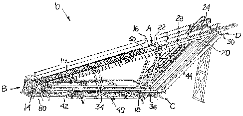
Figures 1 through 5 show one embodiment of the apparatus (10) of the present
invention in
different configurations. In general, the apparatus (10) comprises a support
frame having a
ground section (42) and a rig section (44), a catwalk platform (12), a slide
platform (20), a
skate or conveyor for moving the drill pipe (50) and a hydraulically actuated
piston assembly
(38). Figure 1 depicts the apparatus (10) in a transportation configuration in
which the ground
and rig sections (42, 44) of the support frame are folded against each other,
as well as the
catwalk platform (12) and the slide platform (20). Figure 2 shows the
apparatus (10) in its
loading configuration in which the catwalk platform (12) is substantially
horizontal, while the
slide platform (14) is inclined. Figures 3 to 5 show the apparatus (10) in its
delivery
configuration in which the catwalk platform (12) and the slide platform (20)
are in
substantially coplanar alignment to define a single delivery platform that is
inclined.
The support frame may comprise any suitably sized and constructed structure to
support the
catwalk platform (12) and the slide platform (20). The support frame has a
ground end (80) at
one end of its ground section (42) and a rig end (82) at the opposing end of
the rig section
(44). The rig end is elevated when the apparatus (10) is in the loading
configuration. The
ground section (42) and the rig section (44) are pivotally connected by hinged
connection
(C). The hinged connection (C) allows the apparatus (10) to be folded into the
transportation
configuration shown in Figure 1 and unfolded into the loading configuration
shown in Figure
2. Further, the hinged connection (C) allows the position of the rig end (82)
relative the
ground to be varied so that the apparatus (10) may be used with drilling rigs
having rig floors
at different heights.
The catwalk platform (12) may comprise any suitably sized and constructed
surface to
support a drill pipe lengthwise in the path travelled by the drill pipe skate
or conveyor (50).
In the embodiment shown in Figures 1 to 5, the catwalk platform (12) is an
elongated
rectangular plate having a first end (14) and a second end (16). The first end
(14) of the
catwalk platform (12) is pivotally connected to the ground end (80) of the
ground section (42)
5
CA 02864939 2014-08-19
WO 2013/123602
PCT/CA2013/050138
by hinged connection (B). In one embodiment not shown, the catwalk platform
(12) may be
made of several segments that may be pinned together. For example, the catwalk
platform
(12) may comprise two segments, each having a length of 30 feet. One of the
segments
comprises the first end (14), while the other segment comprises the second end
(16). When
the apparatus is in use, the adjacent ends of the two segments are pinned
together. When the
apparatus is in the transportation configuration, the two segments can be
unpinned from each
other to make the apparatus (10) more compact so that it can be transported
more easily in
congested environments.
The slide platform (20) may comprise any suitably sized and constructed
surface to support a
drill pipe lengthwise in the path travelled by the powered means (50). In the
embodiment
shown in Figures 1 to 5, the slide platform (20) is an elongated rectangular
plate having a first
end (22) and a second end (24). The first end (22) of the slide platform (20)
is pivotally
connected to the second end (16) of the catwalk platform (12) by a hinged
connection (A).
The second end (24) of the slide platform (20) is pivotally and
translationally connected to
the rig end (82) of the rig section (44) of the support frame by connection
(D). In one
embodiment, connection (D) comprises a primary roller upon which the slide
platform rests,
and secondary rollers that fit between the flanges of an I-beam section
attached to the slide
platform (20). The slide platform (20) also has safety railings (28) that can
be used to aid
access and which serve as safety stops to restrain drill pipes that become
dislodged from the
powered means (50) during the delivery to the rig floor.
The drill pipe skate or conveyor for moving the drill pipe may comprise any
suitable means
capable of pushing drill pipe along a path along the catwalk platform (12) and
the slide
platform (20). In one embodiment, as shown in the Figures, the skate or
conveyor comprises
a powered skate, which is well known in the art. In one embodiment, the skate
(50) is self
tensioning and does not require manual adjustment on set up of the apparatus
(10). In one
embodiment, the skate (50) is driven by two independent chain drives each
having an ANSI
120 chain size, giving complete redundancy for safety and capabilities of a
combined pushing
force of up to 13,636 kg (30,000 lbs). In another embodiment, not shown, the
means may
comprise a conveyor on each of the catwalk platform (12) and the slide
platform (20). In
embodiments where the catwalk platform (12) is comprised of multiple segments,
each of the
segments may be provided with its own conveyor. The conveyor may comprise a
conveyor
belt or conveyor chain.
6
CA 02864939 2014-08-19
WO 2013/123602
PCT/CA2013/050138
The piston assembly (38) may comprise any mechanical actuator that applies an
axial force
through an axial stroke, such as a hydraulic cylinder. The piston assembly
(38) is connected
to either the catwalk platform (12) or to the slide platform (20) to pivot the
catwalk platform
(12) and the slide platform (20) between the loading configuration and the
delivery
configuration. In one embodiment, the piston assembly (38) is mounted in the
ground section
(42) in a substantially horizontal orientation and connected to the catwalk
platform (12) by
retractable struts (36). One end of the struts (36) is pivotally connected to
rollers that move
on tracks (not shown) extending along the ground section (42) of the support
frame. The
other end of the struts (36) is pivotally connected to the second end (16) of
the catwalk
platform (12). When the apparatus is in the transportation configuration or
the loading
configuration as shown in Figure 2, the hydraulic pistons (38) are fully
retracted and the
struts (36) are in a substantially horizontal orientation beneath the catwalk
platform (12)
within the ground section (42), and substantially parallel to both the catwalk
platform (12)
and ground section (42). Upon being extended, the pistons (38) push the
connected end of the
struts (36) so that they roll along the track towards the hinged connection
(C). This causes the
struts (36) to pivot into a more vertically inclined orientation and drive the
second end (16) of
the catwalk platform (12) upwards. Consequently, catwalk platform (12) pivots
about hinged
connection (B) into a more vertically inclined angle, while the slide platform
(20) pivots
about hinged connections (A) and about the primary roller of connection (D) to
a less steeply
inclined angle. Simultaneously, the second end (24) of the slide platform (20)
translates away
from the ground end (80) by rolling action of the primary and secondary
rollers, so as to
extend further over the plate (30). This continues until the catwalk platform
(12) and the slide
platform (20) are in substantially coplanar alignment to define the single
vertically inclined
delivery platform in the delivery configuration as shown in Figures 3 to 5.
In one embodiment, the apparatus also has access stairs (26) that are mounted
on the driller's
side of the rig section (44) of the support frame to facilitate access to and
from the rig floor as
shown in the Figures. In a preferred embodiment, the stairs (26) and the
surfaces of the
catwalk platform (12) and the slide platform (20) are coated in an anti-slip
covering to
promote worker safety.
In one embodiment, the apparatus (10) also has an extension platform (90) that
telescopically
extends from the slide platform (20), as shown in Figure 10D. When the
apparatus (10) is in
the delivery configuration, the extension platform (90) extends in
substantially coplanar
7
CA 02864939 2014-08-19
WO 2013/123602
PCT/CA2013/050138
alignment with the delivery platform, away from the ground end (82). This
allows the
delivery platform to extend further over a rig floor and facilitates the
delivery of the drill
pipes and rig equipment in a more controlled and accurate manner. The
extension platform
(90) may be configured to extend to whatever length is desired by the end
user. In one
embodiment, the extension platform (90) may telescope out from the slide
platform (20) by
up to 7 feet.
In one embodiment, the apparatus (10) has safety pins (39) positioned along
the periphery of
the upper surface of the catwalk platform (12). These safety pins (39) are
horizontally
oriented when the apparatus is in the loading configuration but are actuated
into a vertical
position that is perpendicular to the upper surface of the catwalk platform
(12) as the catwalk
platform (12) is elevated. The safety pins (39) prevent drill pipes from
rolling off the catwalk
platform (12), as shown in Figure 4. In one embodiment, a simple cylinder
drive gear raises
and lowers the safety pins (39).
In one embodiment, the apparatus (10) also has extendible hydraulic arms (34)
pivotally
connected to the support frame and to the catwalk platform (12), preferably at
a position that
is approximately equidistant from the first end (14) and the second end (16)
of catwalk
platform (12). When the apparatus (10) is in the loading configuration as
shown in Figure 2,
the hydraulic arms (34) are retracted and in a substantially horizontal
orientation, When the
apparatus (10) is in the delivery configuration as shown in Figures 3 to 5,
the hydraulic arms
(34) are extended and pivot into a vertically inclined orientation. In this
manner, the hydraulic
arms (34) aid the piston assembly (38) in pivoting the catwalk platform (12)
and the slide
platform (20) into the delivery configuration.
In one embodiment, the apparatus (10) also has hydraulic stopper pins (41). In
the
embodiment shown in the Figures, the hydraulic stopper pins (41) are mounted
in sleeves on
the ground section (42) of the support frame. When the apparatus is moving
from the loading
configuration to delivery configuration, the stopper pins (41) rise from their
sleeves and push
upwardly against the catwalk platform (12), as shown in Figure 2. In this
manner, the
hydraulic stopper pins aid the piston assembly (38) as it begins to drive the
catwalk platform
(12) and the slide platform (20) into the delivery configuration. The raised
stopper pins (41)
also prevent drill pipes from rolling off the pipe rack (18) and into the zone
below the raised
catwalk platform (12), as shown in Figure 4. When the apparatus is moving from
the delivery
configuration to the loading configuration, the stopper pins (41) retract
gradually into sleeves
8
CA 02864939 2014-08-19
WO 2013/123602
PCT/CA2013/050138
as they make contact with the descending catwalk platform (12).
In one embodiment, the apparatus (10) also has pipe racks (18). In one
embodiment, as
shown in Figure 1 to 5, the pipe racks (18) are pivotally connected to the
ground section (42)
of the support frame by hinged connections permitting the pipe racks (18) to
be folded
relative to the support frame. In the transportation configuration shown in
Figure 1, the pipe
racks (18) are folded against the support frame so that they are flush and
parallel with the
support frame (42, 44). In the loading or delivery configurations shown in
Figures 2 to 5, the
pipe racks (18) extend outwardly from the catwalk platform (12) from one end
that abuts with
and is level with the catwalk platform (12) to another end that is distal to
the catwalk
platform,
In one embodiment, the pipe racks (18) have a series of legs (40) that are
variable in height,
such as by hydraulic extension. These legs (40) help to stabilize the
apparatus (10) and may
be used in levelling the apparatus (10), as will be described below. Further,
the hydraulic legs
(40) may also be raised or lowered to level the pipe rack (18) with the
catwalk platform (12)
as shown in Figure 9A, incline the pipe rack (18) away from the catwalk
platform (12) when
unloading pipe from catwalk platform (12) as shown in Figure 9B, or incline
the pipe rack
(18) towards the catwalk platform (12) when loading drill pipe onto the
catwalk platform (12)
as shown in Figure 9C.
In one embodiment, the catwalk platform (12) defines a trough (51) shaped to
receive the
drill pipe lengthwise in the skate path. In the embodiment shown in Figures 6
and 7, the
trough (51) is formed centrally in the upper surface of the catwalk platform
(12),
In one embodiment, the apparatus (10) has a conveyor (10) to selectively
transport the drill
pipe along the catwalk platform either to or away from the skate path. In the
embodiment
shown in Figure 6 and 7, the conveyors are implemented in the form of left and
right chain
drives (43) and (45) on the upper surface of the catwalk platform (12). The
chain drives (43,
45) selectively transport drill pipe one at a time either laterally towards,
or away from the
central trough (51) and powered means (50), from either side of the trough
(51).
In one embodiment, the apparatus (10) has hydraulically actuated kickers (60,
62) as shown
in Figures 8A to 8D. The kickers (60, 62) are positioned to selectively
prevent the drill pipe
from entering the skate path or to kick the drill pipe out of the skate path,
or both. Figure 8A
shows the kickers (60, 62) fully extended to prevent drill pipes from entering
the skate path.
9
CA 02864939 2014-08-19
WO 2013/123602
PCT/CA2013/050138
Figure 8B shows the kicker (60) extended to push a drill pipe out of and to
the left of the
skate path. Figure 8C shows the kicker (60) extended to push a drill pipe out
of and to the
right of the skate path. Figure 8D shows the kickers (60, 62) fully retracted
to allow the drill
pipe into the skate path, ready to be raised by the powered means (50).
In one embodiment, the apparatus has indexers (64) as shown in Figures 9A
through 9C. The
indexers (64) may be used to control the delivery of drill pipe from the pipe
racks (18) to the
catwalk platform (12), and vice versa. In one embodiment, the indexer (64)
comprises a
segment of square tube and a hydraulically actuated piston connected to each
end of the tube.
The square tube lays lengthwise perpendicular to the length of the drill pipes
and beneath the
drill pipes. The pistons may be selectively actuated to extend upwardly and
retract
downwardly to incline the square tube either downwards towards the path so as
to urge a drill
pipe on the tube from the pipe rack (18) onto the catwalk platform (12), or to
incline the
square tube downwards away from the path so as to urge a drill pipe on the
tube from the
catwalk platform (12) onto the pipe rack (18). Other types of indexers known
in the art may
also be used to the same effect.
The aforementioned elements of the apparatus (10) may work cooperatively to
provide a
powered and automated system for loading drill pipe from the pipe racks (18)
into the skate
path, and unloading drill pipe from the skate path to the pipe racks (18), as
will be explained
below.
In one embodiment, as shown in Figures 1 to 5, the apparatus (10) has a
hydraulic tailing
winch (52) mounted on a pedestal on the catwalk platform (12). The pedestal
may be
releasably pinned to the catwalk platform (12) to facilitate removal of the
winch (52). In one
embodiment, the winch will have sufficient single line pull capacity for its
intended purpose,
which may be about 12,000 lbs. The purpose of the winch (52) is to limit
uncontrolled
swinging of equipment lifted by the apparatus, as is further explained below.
In embodiment, the apparatus (10) has a removable basket (70) that can be used
to transport
equipment to the rig floor. In the embodiment shown in Figures 12A through
12D, the basket
(70) has removable rails (72), a deck (74), wheels (76), safety latch (78) and
V-roller (79), As
shown in Figures 11, 12A and 12C, the skate (50) engages the deck (74) and is
used to move
the basket (70) along the length of the catwalk platform (12) and the slide
platform (20). The
V-roller (79) fits into the trough (51) formed in the catwalk platform. The
baskets (70) may
CA 02864939 2014-08-19
WO 2013/123602
PCT/CA2013/050138
be placed onto the catwalk platform and removed from the catwalk platform (12)
by any
suitable means such as a forklift. The basket may be loaded with equipment to
be delivered to
the rig floor such as slips and, as shown in Figures 10A through 10C, the
apparatus (10) is
powerful enough to deliver a top drive (77) to the rig floor, As shown in
Figures 10B and
10C, as equipment is winched from the basket (70) to the rig floor, the line
from the hydraulic
tailing winch (52) is attached to the piece of equipment to provide resistance
to prevent any
swinging motion which would be extremely dangerous to those working on the rig
floor.
The use and operation of the apparatus are now described. The apparatus (10)
may be
delivered in its transportation configuration, as shown in Figure 1, to the
drill rig. In one
embodiment, the apparatus (10) is relatively compact in its transportation
configuration so
that it can be transported by conventional means, such as a low boy trailer.
At the drill rig, the apparatus (10) is placed on the ground beneath the V-
door such that the
longitudinal axis of the catwalk platform (12) is suitably aligned to the V-
door, and the
ground section (42) of the support frame rests on the ground. The catwalk
platform (12) and
the slide platform (20) are pivoted about hinged connection (A), and the
ground section (42)
and the rig section (44) of the support frame are pivoted about hinged
connection (C) so that
the plate (30) rests on the V-door area of the rig floor as shown in Figure
10A. In one
embodiment, the slide platform (20) is vertically inclined at approximately 45
degrees above
the horizontal when the apparatus (10) is in the loading configuration. The
hydraulic legs (40)
are lowered to the ground and adjusted in height to level the catwalk platform
(12). Blocks
and shims may be placed between the ground section (42) of the support frame
and the
ground as required. The hydraulic legs (40) are then retracted and the hinged
pipe racks (18)
pivoted out from the ground section (42) of the support frame so that they
extend outward
from the catwalk platform (12) to support drill pipe substantially aligned
with the catwalk.
The hydraulic legs (40) are once again lowered to the ground. Access stairs
(26) and the
safety railings may then be mounted on the slide platform (20). At this point,
the apparatus
(10) has the configuration depicted in Figure 2. If present, the extension
platform (90) may be
telescopically extended out over the rig floor by the desired amount as shown
in Figure 10D.
If drill pipe is to be delivered to the rig floor, multiple drill pipes (19)
are loaded onto the
pipe racks (18). To deliver the drill pipe from the drill pipe racks (18) to
the skate path, the
hydraulic legs (40) may be adjusted in height to incline the drill pipe racks
(18) towards the
skate path as shown in Figure 9C, so that the drill pipes tend to roll towards
the catwalk
11
CA 02864939 2014-08-19
WO 2013/123602
PCT/CA2013/050138
platform (12). The chain drives (43, 45) deliver lengths of drill pipe (19)
one at a time to the
trough (51) and allow loading from either side. Combined use of the pipe racks
(18), chain
drives (43 and 45), the kickers (60 and 62) and the indexers (64) allows the
operator to
manipulate the drill pipe about the catwalk platform (12) and into the skate
path one-by-one.
As shown in Figures 6 and 7, the chain drives (43 and 45) on the catwalk
platform (12) may
be loaded with a plurality of drill pipes when the apparatus is in the loading
configuration.
The chain drives (43 and 45), kickers (60 and 62) and indexers (64) can then
be used to
facilitate automatic sequential loading of the drill pipes (19) one length at
a time into the
trough when the apparatus (10) is in delivery configuration. For example, in
one embodiment,
up to 11 lengths of drill pipe may be loaded onto the catwalk platform,
Conversely, multiple
lengths of drill pipe may be unloaded onto the catwalk platform (12) when in
the loading
configuration. This distinguishes the apparatus (10) over other automated
catwalk platforms
that elevate but which must be raised and lowered for each individual drill
pipe
loading/unloading cycle.
To deliver drill pipe to the rig floor, the hydraulic pistons (38) and the
hydraulic arms (34) are
extended. The retractable struts (36) are pushed towards the second end (16)
of the catwalk
platform (12) thereby pivoting the catwalk platform (12) and the slide
platform (20) until they
form a single coplanar delivery platform. In one embodiment, the delivery
platform is
vertically inclined by approximately 15 degrees above the horizontal. The
safety pins (39)
and the stopper pins (41) are raised to prevent the drill pipes from rolling
off the apparatus
(10). At this point, the apparatus (10) is in the delivery configuration
depicted in Figures 3, 4
and 5.
The chain drive (43) delivers drill pipe to the trough (51) and the skate (50)
individually. The
skate (50) is activated and the drill pipe is pushed up the catwalk platform
(12) and the slide
platform (20). The drill pipe is delivered to the rig floor at a relatively
low angle, in one
embodiment at approximately 15 degrees, and in a controlled manner. The drill
pipe is then
raised into the elevator and the skate (50) returns to the first end (14) of
the catwalk platform
(12) ready to transport the next length of drill pipe. If drill pipe is being
tripped out of the
well, the operation is reversed. If other types of equipment are to be
transported between the
ground and the rig floor, the basket (70) is placed on the catwalk platform
(12).
In one embodiment, the cycle time to deliver a single drill pipe from the
drill pipe rack (18)
to the elevator latch point on the rig floor may be approximately 45 seconds.
This time may
12
CA 02864939 2014-08-19
WO 2013/123602
PCT/CA2013/050138
be reduced if drill pipes are moved from the catwalk platform surface indexers
(64) to the
skate (50).
The interconnected catwalk platform (12) and slide platform (20), the support
frame (42, 44),
the retractable struts (36) and the hydraulic arms (34) collectively provide a
stable delivery
platform that is able to cope with heavy loads regardless of the height of the
drilling floor,
The present invention may use less energy to raise a length of drill pipe to
the rig floor in
comparison to the use of a skate with a conventional catwalk system.
The apparatus (10) is relatively quiet compared to prior art devices and in
one embodiment,
the apparatus (10) operates at below 65 decibels. When in its elevated
delivery configuration,
workers may walk up and down the slide platform (20) and the catwalk platform
(12) when
the catwalk controls are not in use. In one embodiment there are dual control
panels for the
apparatus located at the ground level and on the rig floor.
As will be apparent to those skilled in the art, various modifications,
adaptations and
variations of the foregoing specific disclosure can be made without departing
from the scope
of the invention claimed herein.
13