Note : Les descriptions sont présentées dans la langue officielle dans laquelle elles ont été soumises.
CA 02865434 2014-09-25
266327
METHOD FOR PREDICTING AN AUXILIARY POWER UNIT FAULT
BACKGROUND OF THE INVENTION
Contemporary aircraft may include an auxiliary power unit (APU) in addition to
main
propulsion engines. The APU may perform a variety of functions including
providing
secondary power to the aircraft as well as providing pressurized bleed air for
main engine
starting and the aircraft's environmental control system. Currently,
airlines and
maintenance personnel wait until a fault or problem occurs with the APU and
then
attempt to identify the cause and fix it either during scheduled or, more
likely,
unscheduled maintenance. Fault occurrences are also recorded manually based on
pilot
discretion.
BRIEF DESCRIPTION OF THE INVENTION
In one embodiment, the invention relates to a method of predicting an
auxiliary power
unit fault in an aircraft having an auxiliary power unit and multiple sensors
including
receiving, during pre-flight or post-flight, a sensor signal from at least one
of the multiple
sensors to define a sensor output, comparing, by a controller, the sensor
output to a
reference value for the sensor output, predicting, by a controller, a fault in
the auxiliary
power unit based on the comparison, and providing, by a controller, an
indication of the
predicted fault
BRIEF DESCRIPTION OF THE DRAWINGS
In the drawings:
Figure 1 is a schematic view of an auxiliary power unit, systems related to
the auxiliary
power unit, and sensors;
Figure 2 is a perspective view of the aircraft and a ground system in which
embodiments
of the invention may be implemented; and
1
CA 02865434 2014-09-25
266327
Figure 3 is a flowchart illustrating a method of predicting an auxiliary power
unit fault
according to an embodiment of the invention.
DESCRIPTION OF EMBODIMENTS OF THE INVENTION
Figure 1 schematically depicts an APU 10 in the form of a gas turbine engine
that
includes a combustion system 12, a power turbine 14, and a compressor 16.
During
operation of the APU 10, the compressor 16 draws in ambient air, compresses
it, and
supplies the compressed air to the combustion system 12. The combustion system
12
receives fuel from a fuel source, schematically illustrated with arrows 18,
and the
compressed air from the compressor 16, and supplies high-energy combusted air
to the
power turbine 14, causing it to rotate. The power turbine 14 includes a shaft
19 that may
be used to drive a generator 20 for supplying electrical power, and to drive
its own
compressor and/or an external load compressor. More specifically, a gearbox 22
transfers power from the power turbine 14 to an oil-cooled generator 20 to
provide
electrical power. Within the gearbox 22, power may also be transferred to
engine
accessories such as a fuel control unit, a lubrication module, and cooling
fan, none of
which are shown. A starter 24, such as a starter motor, may be mounted on the
gearbox
22 and connected through the gear train to perform the starting function of
the APU 10.
Further, several actuated devices have been illustrated including a flap motor
28, a surge
control valve 30, and a bleed valve 32. The flap motor 28 may control inlet
guide vanes
34, which regulate airflow to the compressor 16. The surge control valve 30
may
maintain stable or surge-free operation of the APU 10. The bleed valve 32
controls a
flow of bleed air from the APU 10 to the bleed air distribution system 36. It
will be
understood that any number of actuated devices may be included in the APU 10
and that
that APU 10 may be operably coupled to any number of related systems.
Further, multiple sensors 38 related to the APU 10, components thereof, and
systems
related thereto may be included. Such multiple sensors 38 may include, by way
of non-
limiting examples, APU bleed air flow sensor, APU bleed air pressure sensor,
APU bleed
air temperature sensor, APU transformer rectifier unit current sensor, APU
transformer
2
CA 02865434 2014-09-25
266327
rectifier unit voltage sensor, APU speed sensor, APU high oil sensor, APU low
oil level
sensor, APU high oil temperature sensor, APU low oil temperature sensor,
exhaust gas
temperature sensor, a fuel flow sensor, a fuel pressure sensor, a surge
control valve
position sensor, and inlet guide vane position sensor, an inlet pressure
sensor, a load
compressor air flow sensor, a load compressor inlet temperature sensor, a load
compressor outlet temperature sensor, a generator frequency sensor, a
generator load
sensor, a generator voltage sensor, a generator oil temperature sensor, etc.
some of which
have been schematically illustrated.
Figure 2 schematically illustrates an aircraft 50 that may execute embodiments
of the
invention and may include one or more propulsion engines 52 coupled to a
fuselage 54, a
cockpit 56 positioned in the fuselage 54, and wing assemblies 58 extending
outward from
the fuselage 54. While the aircraft 50 is illustrated as a commercial aircraft
it will be
understood that the APU 10 may be installed in any suitable aircraft.
Typically, APUs
and related systems such as cooling systems are mounted in a compartment in
the aft
section of the aircraft 50.
One or more control mechanisms 60 may be included in the cockpit 56 and may be
operated by a pilot to start the APU 10, control the position of the flap
motor 28, control
the position of the surge control valve 30, control the position of the bleed
valve 32, etc.
A plurality of additional aircraft systems 62 that enable proper operation of
the aircraft 50
may also be included in the aircraft 50 as well as a controller 64, and a
communication
system having a wireless communication link 68. The controller 64 may be
operably
coupled to the engines 52, the plurality of aircraft systems 62, and the APU
10 including
its various components and the multiple sensors 38. Further, additional
sensors 70, such
as sensors related to the aircraft systems 62, the control mechanism 60, etc.
may be
operably coupled to the controller 64.
The controller 64 may also be connected with other controllers of the aircraft
50. The
controller 64 may include memory 72, the memory 72 may include random access
memory (RAM), read-only memory (ROM), flash memory, or one or more different
3
266327
types of portable electronic memory, such as discs, DVDs, CD-ROMs, etc., or
any suitable
combination of these types of memory. The controller 64 may include one or
more
processors 74, which may be running any suitable programs. The controller 64
may be a
portion of a Flight Management System (FMS) or may be operably coupled to the
FMS.
A computer searchable database of information may be stored in the memory 72
and
accessible by the processor 74. The processor 74 may run a set of executable
instructions
to display the database or access the database. Alternatively, the controller
64 may be
operably coupled to a database of information. For example, such a database
may be stored
on an alternative computer or controller. It will be understood that the
database may be
any suitable database, including a single database having multiple sets of
data, multiple
discrete databases linked together, or even a simple table of data. It is
contemplated that
the database may incorporate a number of databases or that the database may
actually be a
number of separate databases.
The database may store data that may include historical data related to the
APU 10 and its
related systems related to the aircraft 50 and/or to a fleet of aircraft. The
database may also
include reference values for the APU 10 and its related systems.
Alternatively, it is contemplated that the database may be separate from the
controller 64
but may be in communication with the controller 64 such that it may be
accessed by the
controller 64. For example, it is contemplated that the database may be
contained on a
portable memory device and in such a case, the aircraft 50 may include a port
for receiving
the portable memory device and such a port would be in electronic
communication with
controller 64 such that controller 64 may be able to read the contents of the
portable
memory device. It is also contemplated that the database may be updated
through the
wireless communication link 68 and that in this manner, real time information
such as
information regarding historical fleet wide data may be included in the
database and may
be accessed by the controller 64.
Further, it is contemplated that such a database may be located off the
aircraft 50 at a
location such as airline operation center, flight operations department
control, or another
4
Date Recue/Date Received 2021-03-30
CA 02865434 2014-09-25
266327
location. The controller 64 may be operably coupled to a wireless network over
which
the database information may be provided to the controller 64.
While a commercial aircraft has been illustrated, it is contemplated that
portions of the
embodiments of the invention may be implemented anywhere including in a
controller or
computer 80 at a ground system 82. Furthermore, database(s) as described above
may
also be located in a destination server or a computer 80, which may be located
at and
include the designated ground system 82. Alternatively, the database may be
located at
an alternative ground location. The ground system 82 may communicate with
other
devices including the controller 64 and databases located remote from the
computer 80
via a wireless communication link 84. The ground system 82 may be any type of
communicating ground system 82 such as an airline control or flight operations
department.
One of the controller 64 and the computer SO may include all or a portion of a
computer
program having an executable instruction set for predicting an APU fault in
the aircraft
50. Such faults may include improper operation of components as well as
failure of
components. Regardless of whether the controller 64 or the computer 80 runs
the
program for predicting the fault, the program may include a computer program
product
that may include machine-readable media for carrying or having machine-
executable
instructions or data structures stored thereon. Such machine-readable media
may be any
available media, which can be accessed by a general purpose or special purpose
computer
or other machine with a processor. Generally, such a computer program may
include
routines, programs, objects, components, data structures, algorithms, etc.
that have the
technical effect of performing particular tasks or implement particular
abstract data types.
Machine-executable instructions, associated data structures, and programs
represent
examples of program code for executing the exchange of information as
disclosed herein.
Machine-executable instructions may include, for example, instructions and
data, which
cause a general purpose computer, special purpose computer, or special purpose
processing machine to perform a certain function or group of functions.
CA 02865434 2014-09-25
266327
It will be understood that the aircraft 50 and computer 80 merely represent
two
exemplary embodiments that may be configured to implement embodiments or
portions
of embodiments of the invention. During operation, either the controller 64
and/or the
computer 80 may predict an APU fault. By way of non-limiting example, a
control
mechanism 60 may be utilized to start the APU 10. The controller 64 and/or the
computer 80 may utilize inputs from the control mechanism 60, the multiple
sensors 38,
the database(s) and/or information from airline control or flight operations
department to
predict the APU fault. Among other things, the controller 64 and/or the
computer 80 may
analyze the data output by one or more of the multiple sensors 38 over time to
determine
drifts, trends, steps or spikes in the operation of the APU 10 or its related
systems. Such
anomalies in the data may be too subtle on a day-to-day comparison to make
such
predictions of fault. Once an APU fault has been predicted an indication may
be
provided on the aircraft 50 and/or at the ground system 82. It is contemplated
that the
prediction of the APU fault may be done pre-flight, during flight, may be done
post
flight, or may be done after any number of flights. The wireless communication
link 68
and the wireless communication link 84 may both be utilized to transmit data
such that
the fault may be predicted by either the controller 64 and/or the computer 80.
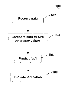
In accordance with an embodiment of the invention, Figure 3 illustrates a
method 100,
which may be used for predicting an APU fault, which can include a failure.
The method
100 begins at 102 by receiving a sensor signal from at least one of the
multiple sensors 38
to define a sensor output. The sensor signal may include information from pre-
flight
and/or post-flight of the aircraft 50, which is when the APU 10 is typically
used. Pre-
flight and post-flight are typically when the aircraft is on the ground. Pre-
flight and post-
flight for purposes of the method 100 may also include when the APU 10 is
rotating
above a certain speed, such as the RPM being above five percent, so that
sensor signals
may be received when the aircraft is taking off and the APU is still being
used to power
the air conditioning. This may include receiving data from one or more of the
multiple
sensors 38. It is contemplated that the sensor output may be raw aircraft data
from which
a variety of other information may be derived or otherwise extracted. For
example, the
6
CA 02865434 2014-09-25
266327
raw data that may be received may consist of temperatures, pressures, valve
and actuator
positions, etc.
The sensor signal may be windowed into the two regimes of pre-flight and post-
flight and
then statistical features may be taken thereof. For example, the received
sensor output
may be aggregated over time to define aggregated sensor data. This may also
include
aggregating the received sensor output over multiple flights. Statistical
features may be
taken of the aggregated data. For example, a median value, a running median
value, a
historical median value, a minimum value, a maximum value, or a range may be
determined. It is also contemplated that other features may be derived using
the sensor
signals, such as the time taken for the APU 10 to start up and the rate at
which the APU
was rotating when the APU 10 ignited. It will be understood that regardless of
whether the data is received directly or derived from sensor output, the data
may be
considered to be sensor output.
At 104, the sensor output may be compared to reference values for the sensor
output. In
the instance where the sensor output includes aggregated sensor data this may
include
comparing the aggregated sensor data to the reference value. The reference
values may
include any number of reference values related to the APU 10, components
thereof, and
systems related thereto. For example, the reference values may include a value
or
suitable range related to temperatures, pressures, valve position, actuator
positions, etc.
The reference values may also include historically defined values or suitable
ranges
related to the APU 10 of the aircraft 50 or historical data for multiple other
aircraft. In
this manner, the reference value may be calculated from historical sensor
output. Thus,
the sensor output may be compared to results obtained from previous flights
for the same
aircraft and against the whole fleet of aircraft. Furthermore, the reference
value may
include a value that has been determined during flight such as by receiving an
output of
one of the multiple sensors 38. In this manner, it will be understood that the
reference
value may be defined during operation. Alternatively, the reference value may
be stored
in one of the database(s) as described above.
7
CA 02865434 2014-09-25
266327
At 106, a fault in the APU 1.0 may be predicted based on the comparison at
104. For
example, a fault in the APU 10 may be predicted when the comparison indicates
the
sensor output satisfies a predetermined threshold. In this manner, the
controller 64 and/or
the computer 80 may determine if the results of the comparison are acceptable.
The term
"satisfies" the threshold is used herein to mean that the variation comparison
satisfies the
predetermined threshold, such as being equal to, less than, or greater than
the threshold
value. It will be understood that such a determination may easily be altered
to be
satisfied by a positive/negative comparison or a true/false comparison. For
example, a
less than threshold value can easily be satisfied by applying a greater than
test when the
data is numerically inverted.
By way of non-limiting example, a time taken for the APU 10 to start may be
determined
from the sensor output; the determined time may then be compared to the
reference value.
If the determined time is larger than the reference value, then a fault may be
predicted
with the APU 10. For example, a fault may be predicted when the comparison
indicates
the time taken for the APU 10 to start up was greater than 50 seconds. As an
additional
example, a fault in the APU 10 may be predicted when the comparison indicates
that a
median inlet temperature in the pre-flight was greater than a reference
temperature, such
as 45 degrees Celsius. More specifically, when all other sensor readings look
normal
such a determination may predict an inlet temperature sensor fault. As yet
another
example, a fault in the APU 10 may be predicted when the comparison indicates
a surge
control valve position is less than or greater than a predetermined position.
For example,
a fault may be predicted when the surge control valve position, in the post-
flight, is
trending away from its long term median position by less than -0.5 degrees or
greater
than 0.5 degrees and may be used to predict a valve fault. Further still, a
fault with the
APU 10 may be predicted when the comparison indicates that the auxiliary power
unit
exhaust gas temperature, during the post-flight, is greater than a
predetermined
temperature. For example, the fault may be predicted when the sensor output
indicates
that the exhaust gas temperature is greater than 600 degrees Celsius. Such a
determination may be used to predict a variety of faults including a load
compressor fault.
8
CA 02865434 2014-09-25
266327
Any number of faults in the APU 10 may be predicted including an inlet
temperature
fault, a starter motor fault, a generator fault, a bleed valve fault, etc.
In implementation, the reference values and comparisons may be converted to an
algorithm to predict faults in the APU 110. Such an algorithm may be converted
to a
computer program comprising a set of executable instructions, which may be
executed by
the controller 64 and/or the computer 80. Additional inputs to the computer
program may
include inputs from the multiple sensors 38, inputs from additional aircraft
systems 62,
inputs from additional sensors 70, etc.
At 108, the controller 64 and/or the computer 80 may provide an indication of
the fault in
the APU 10, as predicted at 106. The indication may be provided in any
suitable manner
at any suitable location including in the cockpit 56, such as on a primary
flight display
(PFD) therein, and at the ground system 82. For example, if the controller 64
ran the
program, then the suitable indication may be provided on the aircraft 50
and/or may be
uploaded to the ground system 82. Alternatively, if the computer SO ran the
program,
then the indication may be uploaded or otherwise relayed to the aircraft 50.
Alternatively, the indication may be relayed such that it may be provided at
another
location such as such as an airline control or flight operations department.
It will be understood that the method of predicting an APU fault is flexible
and the
method illustrated is merely for illustrative purposes. For example, the
sequence of steps
depicted is for illustrative purposes only, and is not meant to limit the
method 100 in any
way as it is understood that the steps may proceed in a different logical
order or
additional or intervening steps may be included without detracting from
embodiments of
the invention. By way of non-limiting example, the method 100 may also include
determining when the APU 10 is in use or determining when the aircraft 50 is
in pre-
flight and/or post-flight. For example, it is contemplated that additional
data such as
altitude and air/ground speed as well as other general performance parameters
output by
the engines 52 may be received and it may be determined therefrom when the
aircraft 50
is in pre-flight and/or post-flight. Furthermore, the method may include
receiving data
9
CA 02865434 2014-09-25
266327
during a number of flights. It is contemplated that different faults may be
detected using
the results of the comparison over a number of flights. It will be understood
that the
number of flights used and the various thresholds set are all configurable.
For example, it
is contemplated that the sensor output may be smoothed to reduce the
oscillations/noise
in the data. This may include taking an average of the sensor output over any
number of
flights. Trends in the sensor output may also be calculated by comparing
current flight
values to those at a steady state in the past, such as an average value over
10 flights 50
flights ago. Further still, the method may include predicting the fault based
on multiple
comparisons.
Beneficial effects of the above described embodiments include that data
gathered by the
aircraft during pre-flight and post-flight may be utilized to predict an APU
fault. This
allows such predicted faults to be corrected before they occur. Currently the
recording of
fault occurrences is discretionary and requires the fault to be entered
manually into a
database this is costly and may not obtain all the relevant information.
Further, there is
currently no manner to predict the fault of an APU. The above described
embodiments
allows for automatic predicting, recording, diagnosing and alerting to users
of faults. The
above embodiments allow accurate predictions to be made regarding the APU
faults. By
predicting such problems sufficient time may be allowed to make repairs before
such
faults occur. This allows for cost savings by reducing maintenance cost,
rescheduling
cost, and minimizing operational impacts including minimizing the time
aircraft arc
grounded. Further, by automating the recording of such faults, human error is
reduced
and a given aircraft's history will be more accurate, which may be helpful in
future
maintenance.
While there have been described herein what are considered to be preferred and
exemplary embodiments of the present invention, other modifications of these
embodiments falling within the scope of the invention described herein shall
be apparent
to those skilled in the art.