Note : Les descriptions sont présentées dans la langue officielle dans laquelle elles ont été soumises.
CA 02865673 2014-08-27
Motor vehicle door lock
Description:
The invention relates to a motor vehicle door lock comprising a locking
mechanism, at
least one locking lever and an electric drive for the locking mechanism with
the electric
drive acting upon the locking mechanism during normal operation for electric
opening and
also provides a mechanical opening of the locking mechanism at least during
emergency
operation.
In a motor vehicle door lock of the described design as disclosed in EP 1 320
652 B1, the
electric drive not only provides the electric opening of the locking
mechanism. Instead, the
electric drive ensures that, for instance, during emergency operation, this
means in the
event of an emergency opening, an external actuating lever is mechanically
connected to
the pawl and/or rotary latch as components of the locking mechanism. In order
to achieve
this, an intermediate lever controllable by the electric drive is provided.
During emergency
opening or during emergency operation, the intermediate lever couples a
triggering lever,
acted upon by the external actuating lever with the aid of a through journal,
to the pawl. As
a result, the external actuating lever can directly mechanically disengage the
pawl during
emergency opening or emergency operation. This ensures an overall reliably
functioning
operation whilst using a simple and cost effective design.
When electrically opening a motor vehicle door, a handle, such as an external
and/or an
internal actuating lever is typically not mechanically connected to the,
locking mechanism.
During normal operation it is instead a sensor acted upon by the respective
handle that
ensures that the electric drive is energized in order to be able to open the
locking
mechanism with the aid of a motor rather than manually. This reduces required
operating
forces and ensures a reliable opening of the locking mechanism. This has
generally
proven to be successful.
Apart from the standard operation this method also covers an emergency
operation or a
so-called emergency opening. Such an emergency operation occurs, for instance,
when
the electric drive no longer works reliably or has ceased to work due to a
drop in voltage in
1
CA 02865673 2014-08-27
the car battery. The emergency operation typically also occurs when directly
after an
accident failure of the electric drive can or must be anticipated. In this
context the
emergency operation ensures that the locking mechanism can be mechanically
opened.
This means that at least during an emergency operation a mechanical connection
is
provided between the handle and the locking mechanism.
Further prior art disclosed in EP 1 225 290 B1 relates to a motor vehicle door
lock with a
pawl drive. The pawl drive uses a driven pulley to act upon a projection in
order to release
the rotary latch.
Finally, DE 695 11 357 T3 discloses an electrically operated lock in which the
central
locking function and an electric opening function can be provided by a common
drive.
In the generic prior art disclosed in EP 1 320 652 B1, a mechanical connection
between
the external actuating lever, internal actuating lever and the locking
mechanism is primarily
provided as part of the emergency opening. In this way, a common "temporary
redundancy" is realized as part of the emergency opening. As such an emergency
opening
is often associated with an accident or crash or occurs as a result thereof,
this is also
referred to in the industry as so-called "TCR" or "temporary crash
redundancy". This
arrangement has proven to be successful but can still be improved further in
respect of
safety aspects.
In the prior art mechanical coupling is actually provided by an intermediate
lever
controllable by the electric drive. This intermediate lever is provided
between the external
actuating lever and triggering lever interacting with the pawl. An additional
locking function
or a locking lever as such is not used.
The invention is based on the technical problem of further developing such a
motor vehicle
door latch so that the functional reliability of such a motor vehicle door
lock is further
increased compared to prior art.
2
CA 02865673 2014-08-27
=
In order to solve this technical problem a generic motor vehicle door lock of
the invention is
characterized in that the locking lever constantly retains its "locked"
position during normal
operation ¨ also during electric opening.
The invention therefore first of all uses at least one locking lever. This
locking lever already
differs from the intermediate lever disclosed in EP 1 320 652 B1 as the
intermediate lever
ultimately couples the external actuating lever and the internal actuating
lever to the
triggering lever and works thus like a type of coupling lever.
In contrast, the locking lever of the invention works in such a way that its
"locked" position,
following the usual function, ensures that a mechanical actuation of a handle
has no effect.
Only when the handle in case of an internal actuation is being pulled twice,
is a so-called
"double-stroke" carried out and the locking lever can be moved into the
"locked" position.
This is, however, not mandatory but is owed to the generally required
mechanical
redundancy of electrically opened motor vehicle door locks.
After all, impinging upon the handle usually ensures that an associated signal
generator is
acted upon, which in turn initiates the control of the electric drive in the
sense of "opening".
This means that the handle is not mechanically connected to the locking
mechanism ¨ at
least during normal operation. Instead, it is only the impinging upon the
signal generator
assigned to the handle that ensures that the locking mechanism is electrically
opened. For
this purpose, the electric drive normally acts upon a triggering lever, in
turn lifting the pawl
or one of several pawls of the rotary latch.
Opening of the locking mechanism normally requires that the locking lever has
previously
occupied its "locked" position. According to the invention, the locking lever
does, however,
constantly retain its "locked" position during normal operation and also
during electric
opening. This ensures that also in the event of an accident the locking lever
still retains its
"locked" position. As a result, any unintentional opening of the door is in
any case
prevented. Even if the handle is unintentionally acted upon as a result of the
generated
forces, the locking mechanism cannot open as the locking lever located or
remaining in the
"locked" position during normal operation, ensures the required mechanical
interruption of
the actuating lever chain from the handle up to the locking mechanism.
3
CA 02865673 2014-08-27
Only after switching from normal operation to emergency operation is the
locking lever
moved into the "unlocked" position by the electric drive. The handle is then
able to
mechanically open the locking mechanism. Again, a temporary mechanical
redundancy is
provided, typically applied immediately after an accident or a crash, as
described above.
This considerably enhances safety as the change from normal operation to
emergency
operation typically occurs after triggering of, for instance, an airbag sensor
and after a time
delay.
During the change from the normal to the emergency operation, the electric
drive ensures
that the locking lever assumes its "unlocked" position. This does, however,
only occur after
any safety-relevant sensors have been triggered, activating e.g. side airbags,
steering
wheel air bags, passenger air bags, a potential belt tightener, crash sensor,
etc.
This means that the transition from normal operation to emergency operation is
only
carried out automatically with the aid of the electric drive, when all safety-
relevant systems
have been activated, ensuring and being able to ensure optimum passenger
protection.
Where in such a situation the electric supply of the drive is no longer
ensured and it can
therefore not automatically switch from the normal to the emergency operation
in order to
move the locking lever into its "unlocked" position, unlocking and a
subsequent manual
opening operation are still possible. Arriving emergency services can
mechanically open
the motor vehicle door lock after unlocking it from the inside. Using the
"double-stroke
actuation", passengers inside the car can unlock the lock during a first
stroke and open the
lock and door in a second stroke. These are the main advantages.
In order to achieve this in detail, the electric drive regularly contains a
safety lock. The
safety lock ensures that, in particular during electric opening, the locking
lever is retained
in its "locked" position. This means that the safety lock ensures that the
mechanism is not
unlocked when during normal operation an opening signal is generated through
the
internal actuating lever. The invention does, however, ensure that the locking
lever
assumes its "locked" position during electric opening as the function
"electric opening" and
"locking" share the same direction of rotation.
4
CA 02865673 2014-08-27
In order to achieve this in detail, the safety lock is designed as blocking
contour
cooperating with a projection on the locking lever. The safety lock or the
blocking contour
is generally located on a driven pulley of the electric drive.
The electric drive as such generally comprises at least an electric motor,
driving a worm
gear and a driven pulley meshing with the worm gear. In this way, the electric
drive can
define a first drive direction corresponding to the normal operation and a
second drive
direction associated with the emergency operation. Generally, the first drive
direction
corresponds to a counter-clockwise rotation of the driven pulley, whilst the
second drive
direction corresponds to a clockwise rotation of the driven pulley. The drive
directions can,
however, also be reversed.
The electric drive also typically contains an opening contour which cooperates
with the
triggering lever impinging upon the locking mechanism during electric opening.
This
opening contour can be an opening cam or similar.
The electric drive also contains a return spring. This return spring can be a
centre/zero
spring, advantageously integrated in the driven pulley. The return spring
ensures that after
being impinged on, the electric drive does and can assume a neutral position
in the first or
second drive direction.
Furthermore a blocking lever is provided, selectively cooperating with the
electric drive.
For this purpose, the electric drive also contains a recess advantageously
located in the
driven pulley ¨just like the opening contour.
Generally a signal generator is allocated to a blocking lever. This signal
generator can be
a signal generator interacting with the handle, as the blocking lever is
regularly acted upon
and deflected with the aid of the handle. As soon as the handle is being
impinged upon not
only the signal generator is activated but also the blocking lever is pivoted
away from the
electric drive. As a result, the blocking lever is able to absorb or block any
incorrect
energizing of the electric drive. Such incorrect energizing would result in
the handle not
being impinged upon. In this case, the blocking lever is also not impinged
upon and is thus
CA 02865673 2014-08-27
able to block the electric drive so that the locking mechanism does not open
unintentionally.
As a result of the mechanical coupling of the blocking lever with the handle,
situations can
arise in which the handle and thus the blocking lever is impinged upon and
during an
already initiated electric opening process. In order to be able to still
process such a
scenario or repeat impinging upon the handle and thus of the blocking lever as
well as of
the signal generator in such a situation, said recess is provided on the
electric drive or the
respective driven pulley. A blocking projection of the blocking lever actually
enters the
respective recess in this scenario, so that the electric opening process,
already initiated
during the first actuation, is not affected. The signal generator is free and
can process the
signals.
Lastly, a stop is assigned to the electric drive and/or the locking lever.
This stop can be a
combined stop or an associated stop contour, designed for a cooperation with
the electric
drive and the locking lever. The stop or stop contour can typically be
connected to a
(plastic) door lock housing and can in turn be made of a thermoplastic
material such as
PUR (Polyurethane).
Below, the invention is explained in detail with reference to a drawing
showing only one
embodiment example, in which:
Fig. 1 shows a front view of the motor vehicle door lock of the invention,
Fig. 2 shows a rear view of the object of Fig. 1 and
Fig. 3 shows an enlarged view of the driven pulley and the locking lever
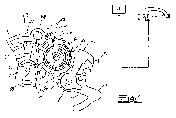
The figures show a motor vehicle door lock containing a locking mechanism ¨
not
expressly shown. Indeed the locking mechanism comprises as usually a rotary
latch and a
pawl. The pawl is acted upon by a triggering lever 1 pivotally mounted in a
lock housing or
lock case around axis 2. As soon as the triggering lever 1 carries out or can
carry out a
clockwise rotary movement around its axis 2, as indicated in Fig. 1, the
triggering lever 1 is
6
CA 02865673 2014-08-27
able to lift the pawl of the rotary latch. The functionality is similar to
that disclosed in more
detail in EP 1 320 652 B1 as described above.
The figure also shows a locking lever 3, pivotally mounted around an axis 4.
In the
diagram shown in Fig. 1, the locking lever 3 assumes its "locked" (VR)
position. Fig. 1 also
shows the "unlocked" position (ER) of the locking lever 3.
The basic arrangement also includes an electric drive 5, 6 7. The electric
drive 5, 6, 7
comprises an electric motor 5, a worm gear 6 impinging upon the electric motor
5 as well
as a driven pulley 7, meshing with the worm gear 6. The driven pulley 7 is
able to pivot
around its axis A and, in relation to Fig. 1, in counter-clockwise direction
of a first drive
direction and in clockwise direction in accordance with a second drive
direction
In normal operation, a handle 9 together with a signal generator 10 ensure
that the
opening movements on the handle 9 are registered by the signal generator 10
and are
transmitted to a control unit 8. The control unit 8 interprets a respective
impinging on the
signal generator 10 in such a way that an associated motor vehicle door is to
be opened.
The control unit 8 therefore ensures that the electric motor 5 is being
energized and in
such a way that the driven pulley 7 carries out a counter-clockwise movement
as indicated
by an arrow in Fig. 1. This counter-clockwise movement in the normal operation
of the
locking mechanism during electric opening with the aid of the electric drive
5, 6, 7
corresponds to the opening contour 11 or an opening cam 11 impinging upon the
triggering lever 1 and pivoting it around its axis of rotation 2 in clockwise
direction as
indicated by an arrow. As a result, the triggering lever 1 ensures that the
pawl is lifted off
the rotary latch which in turn opens with the assistance of a spring (see Fig.
1 and 2).
The opening contour 11 or the opening cam 11 is assigned to the electric drive
5, 6, 7. In
the embodiment, the opening contour or the opening cam 11 is located on the
driven
pulley 7. An additional return spring 12 assigned to the electric drive 5, 6,
7 ensures that
the electric drive 5, 6, 7 returns to a neutral position after being impinged
upon by the
triggering lever 1. For this purpose, said spring 12 is designed as a
centre/zero spring in
the embodiment and is integrated in the driven pulley 7.
7
CA 02865673 2014-08-27
During the described electric opening, a blocking contour 13 on the driven
pulley 7
ensures that the locking lever 3 constantly retains the shown "locked" (VR)
position and
assumed in Fig. 1, as the blocking contour 13 cooperates with a projection 14
on the
respective locking lever 3 during the described opening operation. In this
way, the electric
drive 5, 6, 7 or its driven pulley 7 is equipped with a safety lock which
during electric
opening of the locking lever 3 ensures, as described, that it is retained in
its "locked" (VR)
position. For this purpose, the safety lock or the said blocking contour 13 is
provided at the
driven pulley 7 as part of the electric drive 5, 6, 7.
The handle 9 not only impinges on the signal generator 10 but also on an
additionally
shown blocking lever 15. This blocking lever 15 is mounted on the same axis as
the
triggering lever 1 around the common axis 2. As soon as the handle 9 is
impinged upon by
an operator in the opening sense, the blocking lever 15 pivoted around the
axis 2 in
clockwise direction. As a result, the blocking projection 16 on the blocking
lever 15 is
detached from the electric drive 5, 6, 7 or its driven pulley 7.
If the handle 9 and thus the blocking lever 15 is, however, not acted upon,
the blocking
projection 16 remains engaged in the electric drive 5, 6, 7 and ensures in
case of an
incorrect energizing of the electric drive 5, 6, 7 that its carried out
counter-clockwise
movement is stopped, as during this process, a stop 17 moves against the
respective
blocking projection 16. The pivoting movement carried out by the driven pulley
7 until then
is designed in such a way that such incorrect energizing does and cannot cause
the
locking mechanism to open. Also the stop 17 in connection with the blocking
projection 16
on the blocking lever 15 ensures that the pivoting movement of the electric
drive 5, 6, 7 for
moving the locking lever 3 from its unlocked into its locked position, is
restricted.
If the locking lever 3 is, for instance, in its "unlocked" (ER) position, as
shown by the
dashed lines in Fig. 1, impinging upon the electric drive 5, 6, 7 or upon its
driven pulley 7
in counter-clockwise direction ensures that a locking contour 18 on the driven
pulley 7
engages with the blocking projection 14 of the locking lever 3 pivoting it
from the
"unlocked" (ER) position around the axis 4 in clockwise direction into the
"locked" (VR)
position. The respective pivoting movement of the driven pulley 7 in counter-
clockwise
8
CA 02865673 2014-08-27
direction is restricted by the blocking stop 17 on the driven pulley 7 moving
against the
blocking projection 16 of the blocking lever 15.
When switching from the normal to the emergency operation, this emergency
operation
immediately ensures that the driven pulley 7 does not carry out a counter-
clockwise
movement (first drive direction) via the control unit 8 and the electric motor
5 but is instead
impinged upon in clockwise direction. As a result, the locking or unlocking
contour 18 an
on the driven pulley 7 engages with an unlocking projection 19 on the locking
lever 3 as
the locking lever 3 is in its "locked" (VR) position. As the driven pulley 7
is pivoted
clockwise around it axis A during this process, the interaction between the
unlocking and
locking projection 19 and the unlocking contour 18 ensures that the locking
lever 3 is
pivoted around its axis 4 in counter-clockwise direction. During this process,
the locking
lever 3 leaves the stop 20 and moves against stop 21. At the same time the
locking lever 3
moves its position from "locked" (VR) to "unlocked" (ER).
Both stops 20, 21 are part of the stop contour 23, also containing a stop 22.
This stop 22 is
used as soon as the stop 17 of the electric drive 5, 6, 7 is moved against it
during electric
opening. This is possible as during electric opening, the blocking lever 15 is
pivoted away
with the aid of the handle 9 so that the stop 17 can move past the blocking
lever 15 on the
driven pulley 7.
It is also apparent that the driven pulley 7 contains a recess 24. This recess
24 ensures
that during an already initiated opening process, a repeat actuation of the
handle 9 or
releasing or repeated impinging on the handle 9 by the signal generator 10
assigned to the
blocking lever 15 can be processed. ¨ The stop contour 23 may be made of
plastic and
connected to the motor vehicle door lock housing.
9