Note : Les descriptions sont présentées dans la langue officielle dans laquelle elles ont été soumises.
CA 02868758 2014-10-24
- 1 -
HIGH STRENGTH DISSOLVABLE STRUCTURES FOR USE IN A
SUBTERRANEAN WELL
TECHNICAL FIELD
This disclosure relates generally to equipment utilized and operations
performed in
conjunction with a subterranean well and, in an example described below, more
particularly
provides high strength dissolvable structures for use in a subterranean well.
2.0 BACKGROUND
It is frequently useful to actuate, or otherwise activate or change a
configuration of, a
well tool in a well. For example, it is beneficial to be able to open or close
a valve in a well,
or at least to be able to permit or prevent flow through a flow path, when
desired.
The present inventors have developed methods and devices whereby high strength
dissolvable structures may be used for accomplishing these purposes and
others.
SUMMARY
In the disclosure below, well tools and associated methods are provided which
bring
advancements to the art. One example is described below in which a high
strength structure
formed of a solid mass comprising an anhydrous boron compound is used in a
well tool.
Another example is described below in which the structure comprises a flow
blocking device
in the well tool.
In one aspect, this disclosure provides to the art a unique well tool. The
well tool can
include a flow path, and a flow blocking device which selectively prevents
flow through the
flow path. The device includes an anhydrous boron compound.
In another aspect, a method of constructing a downhole well tool is provided
by this
disclosure. The method can include: forming a structure of a solid mass
comprising an
anhydrous boron compound; and incorporating the structure into the well tool.
CA 02868758 2014-10-24
- 2 -
These and other features, advantages and benefits will become apparent to one
of
ordinary skill in the art upon careful consideration of the detailed
description of
representative examples below and the accompanying drawings, in which similar
elements
are indicated in the various figures using the same reference numbers.
BRIEF DESCRIPTION OF THE DRAWINGS
FIG. 1 is a schematic partially cross-sectional view of a well system and
associated
method embodying principles of the present disclosure.
FIGS. 2A & B are enlarged scale schematic cross-sectional views of a well tool
which
may be used in the system and method of FIG. 1, the well tool blocking flow
through a flow
path in FIG. 2A, and permitting flow through the flow path in FIG. 2B.
FIG. 3 is a schematic cross-sectional view of another well tool which may be
used in
the system and method of FIG. 1.
FIGS. 4A & B are enlarged scale schematic cross-sectional views of another
well tool
which may be used in the system and method of FIG. 1, the well tool blocking
flow through a
flow path in FIG. 4A, and permitting flow through the flow path in FIG. 4B.
FIG. 5 is a schematic cross-sectional view of another well tool which may be
used in
the system and method of FIG. 1.
FIG. 6 is a schematic cross-sectional view of another configuration of the
well tool of
FIG. 5.
DETAILED DESCRIPTION
Representatively illustrated in FIG. 1 is a well system 10 and associated
method
which embody principles of this disclosure. In the system 10, various well
tools 12a-e are
interconnected in a tubular string 14 installed in a wellbore 16. A liner or
casing 18 lines the
wellbore 16 and is perforated to permit fluid to be produced into the
wellbore.
At this point, it should be noted that the well system 10 and associated
method are
merely one example of a wide variety of systems and methods which can
incorporate the
principles of this disclosure. In other examples, the wellbore 18 may not be
cased, or if cased
CA 02868758 2014-10-24
- 3 -
it may not be perforated. In further examples, the well tools 12a-e, or any of
them, could be
interconnected in the casing 18. In still further examples, other types of
well tools may be
used, and/or the well tools may not be interconnected in any tubular string.
In other
examples, fluid may not be produced into the wellbore 18, but may instead be
flowed out of,
or along, the wellbore. It should be clearly understood, therefore, that the
principles of this
disclosure are not limited at all by any of the details of the system 10, the
method or the well
tools 12a-e described herein.
The well tool 12a is representatively a valve which selectively permits and
prevents
fluid flow between an interior and an exterior of the tubular string 14. For
example, the well
tool 12a may be of the type known to those skilled in the art as a circulation
valve.
The well tool 12b is representatively a packer which selectively isolates one
portion
of an annulus 20 from another portion. The annulus 20 is formed radially
between the
tubular string 14 and the casing 18 (or a wall of the wellbore 16 if it is
uncased).
The well tool 12c is representatively a valve which selectively permits and
prevents
fluid flow through an interior longitudinal flow path of the tubular string
14. Such a valve
may be used to allow pressure to be applied to the tubular string 14 above the
valve in order
to set the packer (well tool 12b), or such a valve may be used to prevent loss
of fluids to a
formation 22 surrounding the wellbore 16.
The well tool 12d is representatively a well screen assembly which filters
fluid
produced from the formation 22 into the tubular string 14. Such a well screen
assembly can
include various features including, but not limited to, valves, inflow control
devices, water or
gas exclusion devices, etc.
The well tool 12e is representatively a bridge plug which selectively prevents
fluid
flow through the interior longitudinal flow path of the tubular string. Such a
bridge plug may
be used to isolate one zone from another during completion or stimulation
operations, etc.
Note that the well tools 12a-e are described herein as merely a few examples
of
different types of well tools which can benefit from the principles of this
disclosure. Any
other types of well tools (such as testing tools, perforating tools,
completion tools, drilling
tools, logging tools, treating tools, etc.) may incorporate the principles of
this disclosure.
Each of the well tools 12a-e may be actuated, or otherwise activated or caused
to
change configuration, by means of a high strength dissolvable structure
thereof. For
CA 02868758 2014-10-24
- 4 -
example, the circulation valve well tool 12a could open or close in response
to dissolving of a
structure therein. As another example, the packer well tool 12b could be set
or unset in
response to dissolving of a structure therein.
In one unique aspect of the system 10, the high strength dissolvable structure
comprises an anhydrous boron compound. Such anhydrous boron compounds include,
but
are not limited to, anhydrous boric oxide and anhydrous sodium borate.
Preferably, the anhydrous boron compound is initially provided as a granular
material.
As used herein, the term "granular" includes, but is not limited to, powdered
and other fine-
grained materials.
As an example, the granular material comprising the anhydrous boron compound
is
preferably placed in a graphite crucible, the crucible is placed in a furnace,
and the material is
heated to approximately 1000 degrees Celsius. The material is maintained at
approximately
1000 degrees Celsius for about an hour, after which the material is allowed to
slowly cool to
ambient temperature with the furnace heat turned off.
As a result, the material becomes a solid mass comprising the anhydrous boron
compound. This solid mass may then be readily machined, cut, abraded or
otherwise formed
as needed to define a final shape of the structure to be incorporated into a
well tool.
Alternatively, the heated material may be molded prior to cooling (e.g., by
placing the
material in a mold before or after heating). After cooling, the solid mass may
be in its final
shape, or further shaping (e.g., by machining, cutting abrading, etc.) may be
used to achieve
the final shape of the structure.
Such a solid mass (and resulting structure) comprising the anhydrous boron
compound will preferably have a compressive strength of about 165 MPa, a
Young's
modulus of about 6.09E+04 MPa, a Poisson's ratio of about 0.264, and a melting
point of
about 742 degrees Celsius. This compares favorably with common aluminum
alloys, but the
anhydrous boron compound additionally has the desirable property of being
dissolvable in an
aqueous fluid.
For example, a structure formed of a solid mass of an anhydrous boron compound
can
be dissolved in water in a matter of hours (e.g., 8-10 hours). Note that a
structure formed of a
solid mass can have voids therein and still be "solid" (i.e., rigid and
retaining a consistent
CA 02868758 2014-10-24
- 5 -
shape and volume, as opposed to a flowable material, such as a liquid, gas,
granular or
particulate material).
If it is desired to delay the dissolving of the structure, a barrier (such as,
a glaze,
coating, etc.) can be provided to delay or temporarily prevent hydrating of
the structure due
to exposure of the structure to aqueous fluid in the well.
One suitable coating which dissolves in aqueous fluid at a slower rate than
the
anhydrous boron compound is polylactic acid. A thickness of the coating can be
selected to
provide a predetermined delay time prior to exposure of the anhydrous boron
compound to
the aqueous fluid.
Other suitable degradable barriers include hydrolytically degradable
materials, such
as hydrolytically degradable monomers, oligomers and polymers, and/or mixtures
of these.
Other suitable hydrolytically degradable materials include insoluble esters
that are not
polymerizable. Such esters include formates, acetates, benzoate esters,
phthalate esters, and
the like. Blends of any of these also may be suitable.
For instance, polymer/polymer blends or monomer/polymer blends may be
suitable.
Such blends may be useful to affect the intrinsic degradation rate of the
hydrolytically
degradable material. These suitable hydrolytically degradable materials also
may be blended
with suitable fillers (e.g., particulate or fibrous fillers to increase
modulus), if desired.
In choosing the appropriate hydrolytically degradable material, one should
consider
the degradation products that will result. Also, these degradation products
should not
adversely affect other operations or components.
The choice of hydrolytically degradable material also can depend, at least in
part, on
the conditions of the well, e.g., well bore temperature. For instance,
lactides may be suitable
for use in lower temperature wells, including those within the range of 15 to
65 degrees
Celsius, and polylactides may be suitable for use in well bore temperatures
above this range.
The degradability of a polymer depends at least in part on its backbone
structure. The
rates at which such polymers degrade are dependent on the type of repetitive
unit,
composition, sequence, length, molecular geometry, molecular weight,
morphology (e.g.,
crystallinity, size of spherulites and orientation), hydrophilicity,
hydrophobicity, surface area
and additives. Also, the environment to which the polymer is subjected may
affect how it
CA 02868758 2014-10-24
- 6 -
degrades, e.g., temperature, amount of water, oxygen, microorganisms, enzymes,
pH and the
like.
Some suitable hydrolytically degradable monomers include lactide, lactones,
glycol ides, anhydrides and lactams.
Some suitable examples of hydrolytically degradable polymers that may be used
include, but are not limited to, those described in the publication of
Advances in Polymer
Science, Vol. 157 entitled "Degradable Aliphatic Polyesters" edited by A. C.
Albertsson.
Specific examples include homopolymers, random, block, graft, and star- and
hyper-
branched aliphatic polyesters.
Such suitable polymers may be prepared by polycondensation reactions, ring-
opening
polymerizations, free radical polymerizations, anionic polymerizations,
carbocationic polymerizations, and coordinative ring-opening polymerization
for, e.g.,
lactones, and any other suitable process. Specific examples of suitable
polymers include
polysaccharides such as dextran or cellulose; chitin; chitosan; proteins;
aliphatic polyesters;
poly(lactides); poly(glycolides); poly(E-caprolactones);
poly(hydroxybutyrates); aliphatic
polycarbonates; poly(orthoesters); poly(amides); poly(urethanes); poly(hydroxy
ester ethers);
poly(anhydrides); aliphatic polycarbonates; poly(orthoesters); poly(amino
acids);
poly(ethylene oxide); and polyphosphazenes.
Of these suitable polymers, aliphatic polyesters and polyanhydrides may be
preferred.
Of the suitable aliphatic polyesters, poly(lactide) and poly(glycolide), or
copolymers of
lactide and glycolide, may be preferred.
The lactide monomer exists generally in three different forms: two
stereoisomers L-
and D-lactide and racemic D,L-lactide (meso-lactide). The chirality of lactide
units provides
a means to adjust, among other things, degradation rates, as well as physical
and mechanical
properties.
Poly(L-lactide), for instance, is a semi-crystalline polymer with a relatively
slow
hydrolysis rate. This could be desirable in applications where a slower
degradation of the
hydrolytically degradable material is desired.
CA 02868758 2014-10-24
- 7 -
Poly(D,L-lactide) may be a more amorphous polymer with a resultant faster
hydrolysis rate. This may be suitable for other applications where a more
rapid degradation
may be appropriate.
The stereoisomers of lactic acid may be used individually or combined.
Additionally,
they may be copolymerized with, for example, glycolide or other monomers like
E-
caprolactone, 1,5-dioxepan-2-one, trimethylene carbonate, or other suitable
monomers to
obtain polymers with different properties or degradation times. Additionally,
the lactic acid
stereoisomers can be modified by blending high and low molecular weight
poly(lactide) or by
blending poly(lactide) with other polyesters.
Plasticizers may be present in the hydrolytically degradable materials, if
desired.
Suitable plasticizers include, but are not limited to, derivatives of
oligomeric lactic acid,
polyethylene glycol; polyethylene oxide; oligomeric lactic acid; citrate
esters (such as tributyl
citrate oligomers, triethyl citrate, acetyltributyl citrate, acetyltriethyl
citrate); glucose
monoesters; partially fatty acid esters; PEG monolaurate; triacetin; poly(c-
caprolactone);
poly(hydroxybutyrate); glycerin-1 -benzoate-2, 3 -dilaurate ; glycerin-2-
benzoate-1,3-dilaurate;
starch; bis(butyl diethylene glycol)adipate; ethylphthalylethyl glycolate;
glycerine diacetate
monocaprylate; diacetyl monoacyl glycerol; polypropylene glycol (and epoxy,
derivatives
thereof); poly(propylene glycol)dibenzoate, dipropylene glycol dibenzoate;
glycerol; ethyl
phthalyl ethyl glycolate; poly(ethylene adipate)distearate; di-iso-butyl
adipate; and
combinations thereof.
The physical properties of hydrolytically degradable polymers depend on
several
factors such as the composition of the repeat units, flexibility of the chain,
presence of polar
groups, molecular mass, degree of branching, crystallinity, orientation, etc.
For example,
short chain branches reduce the degree of crystallinity of polymers while long
chain branches
lower the melt viscosity and impart, among other things, elongational
viscosity with tension-
stiffening behavior.
The properties of the material utilized can be further tailored by blending,
and
copolymerizing it with another polymer, or by a change in the macromolecular
architecture
(e.g., hyper-branched polymers, star-shaped, or dendrimers, etc.). The
properties of any such
3 0 suitable degradable polymers (e.g., hydrophobicity, hydrophilicity,
rate of degradation, etc.)
can be tailored by introducing select functional groups along the polymer
chains.
CA 02868758 2014-10-24
- 8 -
For example, poly(phenyllactide) will degrade at about 1/5th of the rate of
racemic
poly(lactide) at a pH of 7.4 at 55 degrees C. One of ordinary skill in the art
with the benefit of
this disclosure will be able to determine the appropriate functional groups to
introduce to the
polymer chains to achieve the desired physical properties of the degradable
polymers.
Polyanhydrides are another type of particularly suitable degradable polymer.
Examples of suitable polyanhydrides include poly(adipic anhydride),
poly(suberic
anhydride), poly(sebacic anhydride), and poly(dodecanedioic anhydride). Other
suitable
examples include, but are not limited to, poly(maleic anhydride) and
poly(benzoic
anhydride).
An epoxy or other type of barrier which does not dissolve in aqueous fluid may
be
used to completely prevent exposure of the anhydrous boron compound to the
aqueous fluid
until the barrier is breached, broken or otherwise circumvented, whether this
is done
intentionally (for example, to set a packer when it is appropriately
positioned in the well, or
to open a circulation valve upon completion of a formation testing operation,
etc.) or as a
result of an unexpected or inadvertent circumstance (for example, to close a
valve in an
emergency situation and thereby prevent escape of fluid, etc.).
Referring additionally now to FIGS. 2A & B, the well tool 12c is
representatively
illustrated in respective flow preventing and flow permitting configurations.
The well tool
12c may be used in the system 10 and method described above, or the well tool
may be used
in any other system or method in keeping with the principles of this
disclosure.
In the configuration of FIG. 2A, the well tool 12c prevents downward fluid
flow, but
permits upward fluid flow, through a flow path 24a which may extend
longitudinally through
the well tool and the tubular string 14 in which the well tool is
interconnected. In the
configuration of FIG. 2B, the well tool 12c permits fluid flow in both
directions through the
flow path 24a.
The well tool 12c preferably includes a structure 26a in the form of a ball
which
sealingly engages a seat 28 in a housing 30. The housing 30 may be provided
with suitable
threads, etc. for interconnection of the housing in the tubular string 14. The
structure 26a
may be installed in the well tool 12c before or after the tubular string 14 is
installed in the
well.
CA 02868758 2014-10-24
- 9 -
The structure 26a comprises an anhydrous boron compound 32a with a barrier 34a
thereon. The anhydrous boron compound 32a may be formed of a solid mass as
described
above. The barrier 34a preferably comprises a coating which prevents exposure
of the
anhydrous boron compound 32a to an aqueous fluid in the well, until the
barrier is
compromised.
With the structure 26a sealingly engaged with the seat 28 as depicted in FIG.
2A, a
pressure differential may be applied from above to below the structure. In
this manner,
pressure may be applied to the tubular string 14, for example, to set a
packer, actuate a valve,
operate any other well tool, etc. As another example, the sealing engagement
of the structure
26a with the seat 28 can prevent loss of fluid from the tubular string 14,
etc.
When it is desired to permit downward flow through the flow path 24a, or to
provide
access through the well tool 12c, a predetermined elevated pressure
differential may be
applied from above to below the structure 26a, thereby forcing the structure
through the seat
28, as depicted in FIG. 2B. This causes the barrier 34a to be compromised,
thereby exposing
the anhydrous boron compound 32a to aqueous fluid in the well. As a result,
the anhydrous
boron compound 32a will eventually dissolve, thereby avoiding the possibility
of the
structure 26a obstructing or otherwise impeding future operations.
Note that the barrier 34a could be made of a material, such as a coating,
which
dissolves at a slower rate than the anhydrous boron compound 32a, in order to
delay exposure
of the anhydrous boron compound to the aqueous fluid.
Referring additionally now to FIG. 3, a cross-sectional view of the well tool
12e is
representatively illustrated. The well tool 12e is similar in some respects to
the well tool 12c
described above, in that the well tool 12e includes a structure 26b which
selectively prevents
fluid flow through a flow path 24b.
However, the structure 26b includes a barrier 34b which isolates an anhydrous
boron
compound 32b from exposure to an aqueous fluid in the well, until the barrier
34b dissolves.
Thus, the structure 26b blocks flow through the flow path 24b (in both
directions) for a
predetermined period of time, after which the structure dissolves and thereby
permits fluid
flow through the flow path.
After the structure 26b dissolves, the only remaining components left in the
housing
30b are seals and/or slips 36 which may be used to sealingly engage and secure
the structure
CA 02868758 2014-10-24
- 1.0 -
in the housing. The seals and/or slips 36 preferably do not significantly
obstruct the flow
path 24b after the structure 26b is dissolved.
Instead of using separate seals, the structure 26b could sealing engage a seat
28b in
the housing 30b, if desired.
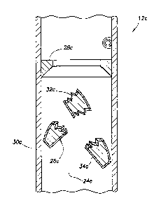
Referring additionally now to FIGS. 4A & B, another construction of the well
tool
12c is representatively illustrated. In FIG. 4A, the well tool 12c is depicted
in a configuration
in which downward flow through the flow path 24c is prevented, but upward flow
through
the flow path is permitted. In FIG. 4B, the well tool 12c is depicted in a
configuration in
which both upward and downward flow through the flow path 24c are permitted.
One significant difference between the well tool 12c as depicted in FIGS. 4A &
B,
and the well tool 12c as depicted in FIGS. 2A & B, is that the structure 26c
of FIGS. 4A & B
is in the form of a flapper which sealingly engages a seat 28c. The flapper is
pivotably
mounted in the housing 30c.
Similar to the structure 26a described above, the structure 26c includes an
anhydrous
boron compound 32c and a barrier 34c which prevents exposure of the anhydrous
boron
compound to aqueous fluid in the well. When it is desired to permit fluid flow
in both
directions through the flow path 24c, the structure 26c is broken, thereby
compromising the
barrier 34c and permitting exposure of the anhydrous boron compound 32c to the
aqueous
fluid.
Preferably, the structure 26c is frangible, so that it may be conveniently
broken, for
example, by applying a predetermined pressure differential across the
structure, or by striking
the structure with another component, etc. Below the predetermined pressure
differential, the
structure 26c can resist pressure differentials to thereby prevent downward
flow through the
flow path 24c (for example, to prevent fluid loss to the formation 22, to
enable pressure to be
applied to the tubular string 14 to set a packer, operate a valve or other
well tool, etc.).
After the anhydrous boron compound 32c is exposed to the aqueous fluid in the
well,
it eventually dissolves. In this manner, no debris remains to obstruct the
flow path 24c.
Note that the barrier 34c could be made of a material, such as a coating,
which
dissolves at a slower rate than the anhydrous boron compound 32c, in order to
delay exposure
of the anhydrous boron compound to the aqueous fluid.
CA 02868758 2014-10-24
- II_ -
Referring additionally now to FIG. 5, a schematic cross-sectional view of the
well
tool 12d is representatively illustrated. The well tool 12d comprises a well
screen assembly
which includes a filter portion 38a overlying a base pipe 40a. The base pipe
40a may be
provided with suitable threads, etc. for interconnection in the tubular string
14.
The filter portion 38a excludes sand, fines, debris, etc. from fluid which
flows inward
through the well screen assembly and into the interior of the base pipe 40a
and tubular string
14. However, when the well screen assembly is initially installed in the well,
a structure 26d
prevents fluid flow between the interior and the exterior of the base pipe
40a.
By preventing fluid flow through the well screen assembly, clogging of the
filter
portion 38a can be avoided and fluid can be circulated through the tubular
string 14 during
installation. In this manner, use of a washpipe in the well screen assembly
can be eliminated,
thereby providing for a more economical completion operation.
After a predetermined period of time (e.g., after installation of the well
tool 12d, after
a completion operation, after gravel packing, etc.), a barrier 34d dissolves
and permits
exposure of an anhydrous boron compound 32d to an aqueous fluid in the well.
The
anhydrous boron compound 32d eventually dissolves, thereby permitting fluid
flow through a
flow path 24d. Thereafter, relatively unimpeded flow of fluid is permitted
through the filter
portion 38a and the flow path 24d between the exterior and the interior of the
well screen
assembly.
Referring additionally now to FIG. 6, another construction of the well tool
12d is
representatively illustrated. The well tool 12d depicted in FIG. 6 is similar
in many respects
to the well tool depicted in FIG. 5. However, the well tool 12d of FIG. 6 also
includes a
check valve 42 which permits inward flow of fluid through the well screen
assembly, but
prevents outward flow of fluid through the well screen assembly.
The check valve 42 includes a flexible closure device 44 which seals against
the base
pipe 40b to prevent outward flow of fluid through the filter portion 38b. This
allows fluid to
be circulated through the tubular string 14 during installation (without the
fluid flowing
outward through the filter portion 38b), but also allows fluid to subsequently
be produced
inward through the well screen assembly (i.e., inward through the filter
portion and check
valve 42). A flow path 46 permits fluid flowing inward through the check valve
42 to flow
into the interior of the base pipe 40b (and, thus, into the tubular string
14).
CA 02868758 2014-10-24
- 12 -
After a predetermined period of time (e.g., after installation of the well
tool 12d, after
a completion operation, after gravel packing, etc.), a barrier 34e dissolves
and permits
exposure of an anhydrous boron compound 32e to an aqueous fluid in the well.
The
anhydrous boron compound 32e eventually dissolves, thereby permitting fluid
flow through a
flow path 24e. Thereafter, relatively unimpeded flow of fluid is permitted
through the filter
portion 38b and the flow path 24e between the exterior and the interior of the
well screen
assembly.
In this manner, the check valve 42 is bypassed by the fluid flowing through
the flow
path 24e. That is, fluid which flows inward through the filter portion 38b
does not have to
flow through the check valve 42 into the base pipe 40b. Instead, the fluid can
flow relatively
unimpeded through the flow path 24e after the structure 26e has dissolved.
Note that the structure 26a-e in each of the well tools described above
comprises a
flow blocking device which at least temporarily blocks flow through a flow
path 24a-e.
However, it should be clearly understood that it is not necessary for a
structure embodying
principles of this disclosure to comprise a flow blocking device.
Furthermore, the structure 26a-e in each of the well tool described above can
be
considered a closure device in a valve of the well tool. Thus, the structure
26a-e in each of
the well tools initially prevents flow in at least one direction through a
flow path, but can
selectively permit flow through the flow path when desired.
One advantage of using the anhydrous boron compound 32a-e in the structures
26a-e
can be that the anhydrous boron compound, having a relatively high melting
point of about
742 degrees Celsius, can be positioned adjacent a structure which is welded
and then stress-
relieved. For example, in the well tool 12d configurations of FIGS. 5 & 6, the
filter portion
38a,b or housing of the check valve 42 may be welded to the base pipe 40a,b
and then stress-
relieved (e.g., by heat treating), without melting the anhydrous boron
compound 32a-e.
It may now be fully appreciated that the above disclosure provides significant
improvements to the art of constructing well tools for use in subterranean
wells. In
particular, use of the anhydrous boron compound permits convenient, reliable
and
economical actuation and operation of well tools.
Those skilled in the art will recognize that the above disclosure provides to
the art a
method of constructing a downhole well tool 12a-e. The method can include
forming a
CA 02868758 2014-10-24
- 13 -
structure 26a-e of a solid mass comprising an anhydrous boron compound 32a-e;
and
incorporating the structure 26a-e into the well tool 12a-e.
Forming the structure 26a-e can include at least one of molding, machining,
abrading
and cutting the solid mass.
The structure 26a-e can comprise a flow blocking device, and the incorporating
step
can include blocking a flow path 24a-e in the well tool 12a-e with the
structure 26a-e.
The anhydrous boron compound 32a-e may comprise at least one of anhydrous
boric
oxide and anhydrous sodium borate.
The method can include the step of providing a barrier 34a-e which at least
temporarily prevents the anhydrous boron compound 32a-e from hydrating. The
barrier 34a-
e may comprise a coating, and may comprise polylactic acid.
The barrier 34a-e may dissolve in an aqueous fluid at a rate slower than a
rate at
which the anhydrous boron compound 32a-e dissolves in the aqueous fluid. The
barrier 34a-
e may be insoluble in an aqueous fluid.
The barrier 34a-e can prevent hydrating of the anhydrous boron compound 32a-e
until
after the well tool 12a-e is installed in a wellbore 16. A pressure
differential may be applied
across the structure 26a-e prior to the barrier 34a-e permitting the anhydrous
boron
compound 32a-e to hydrate.
The structure 26a-e may selectively permit fluid communication between an
interior
and an exterior of a tubular string 14.
The structure 26a-e may selectively block fluid which flows through a filter
portion
38a,b of a well screen assembly.
The well tool 12d may comprise a well screen assembly which includes a check
valve
42, with the check valve preventing flow outward through the well screen
assembly and
permitting flow inward through the well screen assembly. Flow inward and
outward through
the well screen assembly may be permitted when the anhydrous boron compound
32d,e
dissolves.
The structure 26a-c can selectively block a flow path 24a-c which extends
longitudinally through a tubular string 14.
CA 02868758 2014-10-24
- 14 -
The structure 26a-e may comprise a closure device of a valve. The closure
device
may comprise a flapper (e.g., structure 26c) or a ball (e.g., structure 26a),
and the closure
device may be frangible (e.g., structures 26a,c). The anhydrous boron compound
32a,c can
hydrate in response to breakage of the closure device.
The method may include forming the solid mass by heating a granular material
comprising the anhydrous boron compound 32a-e, and then cooling the material.
The
granular material may comprise a powdered material.
Also provided by the above disclosure is a well tool 12a-e which can include a
flow
path 24a-e, and a flow blocking device (e.g., structures 26a-e) which
selectively prevents
flow through the flow path. The device may include an anhydrous boron compound
32a-e.
The flow blocking device may be positioned adjacent a welded and stress-
relieved
structure.
The anhydrous boron compound 32a-e may comprise a solid mass formed from a
granular material.
In a specific example described above, a method of constructing a downhole
well tool
12a-e includes forming a frangible structure 26a-e, the frangible structure
comprising a solid
mass including an anhydrous boron compound; and incorporating the frangible
structure 26a-
e into a valve of the well tool 12a-e.
In another specific example described above, a well screen assembly (well tool
12d)
includes a filter portion 38, a flow path 24e arranged so that fluid which
flows through the
flow path also flows through the filter portion 38, and a flow blocking device
(structure 26e)
which selectively prevents flow through the flow path 24e, the device
including an anhydrous
boron compound 32e.
In other specific examples described above, a well tool 12d includes a flow
path 24d,e
which provides fluid communication between an interior and an exterior of a
tubular string
14, and a flow blocking device (structure 26d,e) which selectively prevents
flow through the
flow path 24d,e. The flow blocking device includes an anhydrous boron compound
32d,e.
Another example described above comprises a well tool 12c which includes a
flow
path 24c and a flapper (structure 26c) which selectively prevents flow through
the flow path.
The flapper includes an anhydrous boron compound 32c.
CA 02868758 2014-10-24
- 15-
ft
is to be understood that the various examples described above may be utilized
in
various orientations, such as inclined, inverted, horizontal, vertical, etc.,
and in various
configurations, without departing from the principles of the present
disclosure. The
embodiments illustrated in the drawings are depicted and described merely as
examples of
useful applications of the principles of the disclosure, which are not limited
to any specific
details of these embodiments.
In the above description of the representative examples of the disclosure,
directional
terms, such as "above," "below," "upper," "lower," etc., are used for
convenience in referring
to the accompanying drawings. In general, "above," "upper," "upward" and
similar terms
refer to a direction toward the earth's surface along a wellbore, and "below,"
"lower,"
"downward" and similar terms refer to a direction away from the earth's
surface along the
wellbore.
Of course, a person skilled in the art would, upon a careful consideration of
the above
description of representative embodiments, readily appreciate that many
modifications,
additions, substitutions, deletions, and other changes may be made to these
specific
embodiments, and such changes are within the scope of the principles of the
present
disclosure. Accordingly, the foregoing detailed description is to be clearly
understood as
being given by way of illustration and example only, the spirit and scope of
the present
invention being limited solely by the appended claims and their equivalents.