Note : Les descriptions sont présentées dans la langue officielle dans laquelle elles ont été soumises.
81783000
INTERFERENCE MITIGATION BASED ON ADAPTIVE TIME DIVISION DUPLEXING
(TDD) CONFIGURATIONS
CROSS-REFERENCE TO RELATED APPLICATION
[0001] This application claims priority to United States Provisional Patent
Application No.
61/641,211 entitled "ANCHOR SUBFRAME ADAPTIVE TDD," filed on May 1, 2012.
BACKGROUND
Field
[0002] Aspects of the present disclosure relate generally to wireless
communication systems, and
more particularly to adjusting downlink/uplink communications based on the
time division
duplexing (TDD) configurations of serving cells and neighbor cells.
Background
[0003] Wireless communication systems are widely deployed to provide various
telecommunication services such as telephony, video, data, messaging, and
broadcasts. Typical
wireless communication systems may employ multiple-access technologies capable
of supporting
communication with multiple users by sharing available system resources (e.g.,
bandwidth,
transmit power). Examples of such multiple-access technologies include code
division multiple
access (CDMA) systems, time division multiple access (TDMA) systems, frequency
division
multiple access (FDMA) systems, orthogonal frequency division multiple access
(OFDMA)
systems, single-carrier frequency divisional multiple access (SC-FDMA)
systems, and time
division synchronous code division multiple access (TD-SCDMA) systems.
[0004] These multiple access technologies have been adopted in various
telecommunication
standards to provide a common protocol that enables different wireless devices
to communicate
on a municipal, national, regional, and even global level. An example of an
emerging
telecommunication standard is Long Term Evolution (LTE). LTE is a set of
enhancements to the
Universal Mobile Telecommunications System (UMTS) mobile standard promulgated
by Third
Generation Partnership Project
- 1 -
CA 2869930 2019-08-09
CA 02869930 2014-10-07
WO 2013/166054 PCT/US2013/038924
(3GPP). It is designed to better support mobile broadband Internet access by
improving
spectral efficiency, lower costs, improve services, make use of new spectrum,
and better
integrate with other open standards using OFDMA on the downlink (DL), SC-FDMA
on the uplink (UL), and multiple-input multiple-output (MIMO) antenna
technology.
However, as the demand for mobile broadband access continues to increase,
there exists
a need for further improvements in LTE technology. Preferably, these
improvements
should be applicable to other multi-access technologies and the
telecommunication
standards that employ these technologies.
[0005] This has outlined, rather broadly, the features and technical
advantages of the
present disclosure in order that the detailed description that follows may be
better
understood. Additional features and advantages of the disclosure will be
described
below. It should be appreciated by those skilled in the art that this
disclosure may be
readily utilized as a basis for modifying or designing other structures for
carrying out
the same purposes of the present disclosure. It should also be realized by
those skilled
in the art that such equivalent constructions do not depart from the teachings
of the
disclosure as set forth in the appended claims. The novel features, which are
believed to
be characteristic of the disclosure, both as to its organization and method of
operation,
together with further objects and advantages, will be better understood from
the
following description when considered in connection with the accompanying
figures. It
is to be expressly understood, however, that each of the figures is provided
for the
purpose of illustration and description only and is not intended as a
definition of the
limits of the present disclosure.
SUMMARY
[0006] According to an aspect of the present disclosure, a method mitigates
interference
in a wireless Time Division Duplex (TDD) network environment. The method
includes
an eNodeB and/or a HE identifying interference on subframes configured for
mismatched uplink and downlink transmissions. The eNodeB may identify the
interfering TDD configurations based on a downlink signal of a neighboring
eNodeB
received during an uplink timeslot for a UE associated with the eNodeB.
Likewise, the
UE may identify an interfering UE based on an uplink signal received during a
downlink timeslot for an eNodeB associated with the UE. The eNodeB performs
interference management based at least in part on the identified interference.
In one
- 2 -
CA 02869930 2014-10-07
WO 2013/166054 PCT/US2013/038924
configuration, the interference management may include specifying different
scheduling
and/or power control for subframes that are mismatched based on the
interfering TDD
configuration. In another configuration, the interference management may
include
cancelling the interfering downlink signal or the interfering uplink signal.
100071 In one aspect of the present disclosure, a method of wireless
communication is
disclosed. The method includes identifying an interfering TDD configuration,
and
interference resulting from a mismatch between an uplink communication of a
first base
station and a downlink communication of a second base station. The method also
includes performing interference management based at least in part on the
identified
interfering TDD configuration.
[0008] Another aspect of the present disclosure discloses an apparatus
including means
for identifying an interfering TDD configuration, and interference resulting
from a
mismatch between an uplink communication of a first base station and a
downlink
communication of a second base station. The apparatus also includes means for
performing interference management based at least in part on the identified
interfering
TDD configuration
[0009] In another aspect of the present disclosure, a computer program product
for
wireless communications in a wireless network having a non-transitory computer-
readable medium is disclosed. The computer readable medium has non-transitory
program code recorded thereon which, when executed by the processor(s), causes
the
processor(s) to perform operations of identifying an interfering TDD
configuration, and
interference resulting from a mismatch between an uplink communication of a
first base
station and a downlink communication of a second base station. The program
code also
causes the processor(s) to perform interference management based at least in
part on the
identified interfering TDD configuration.
[0010] Another aspect of the present disclosure discloses a wireless
communication
apparatus having a memory and at least one processor coupled to the memory.
The
processor(s) is configured to identify an interfering TDD configuration, and
interference
resulting from a mismatch between an uplink communication of a first base
station and
a downlink communication of a second base station. The processor(s) is further
configured to perform interference management based at least in part on the
identified
- 3 -
CA 02869930 2014-10-07
WO 2013/166054 PCT/US2013/038924
interfering TDD configuration.
[0011] In one aspect of the present disclosure, a method of wireless
communication is
disclosed. The method includes measuring, by a UE, uplink interference in a
downlink
subframe of the UE. The method also includes reporting the uplink interference
to an
eNodeB.
[0012] Another aspect of the present disclosure discloses an apparatus
including means
for measuring, by a UE, uplink interference in a downlink subframe of the UE.
The
apparatus also includes means for reporting the uplink interference to an
eNodeB.
[0013] In another aspect of the present disclosure, a computer program product
for
wireless communications in a wireless network having a non-transitory computer-
readable medium is disclosed. The computer readable medium has non-transitory
program code recorded thereon which, when executed by the processor(s), causes
the
processor(s) to perform operations of measuring, by a UE, uplink interference
in a
downlink subframe of the UE. The program code also causes the processor(s) to
report
the uplink interference to an eNodeB.
[0014] Another aspect of the present disclosure discloses a wireless
communication
apparatus having a memory and at least one processor coupled to the memory.
The
processor(s) is configured to measure, by a UE, uplink interference in a
downlink
subframe of the UE. The processor(s) is also configured to report the uplink
interference to an eNodeB.
100151 In one aspect of the present disclosure, a method of wireless
communication is
disclosed. The method includes defining an anchor set of subframes that are
common
across uplink configurations and downlink configurations. The method also
includes
defining a non-anchor set of subframes that are potentially not common across
different
uplink configurations and downlink configurations. The method further includes
signaling the anchor set, and/or the non-anchor set to at least one UE.
[0016] Another aspect of the present disclosure discloses an apparatus
including means
for defining an anchor set of subframes that are common across uplink
configurations
and downlink configurations. The apparatus also includes means for defining a
non-
anchor set of subframes that are potentially not common across different
uplink
- 4 -
81783000
configurations and downlink configurations. The apparatus further includes
means for
signaling the anchor set, and/or the non-anchor set to at least one UE.
[0017] In another aspect of the present disclosure, a computer program product
for wireless
communications in a wireless network having a non-transitory computer-readable
medium is
disclosed. The computer readable medium has non-transitory program code
recorded thereon
which, when executed by the processor(s), causes the processor(s) to perform
operations of
defining an anchor set of subframes that are common across uplink
configurations and
downlink configurations. The program code also causes the processor(s) to
define a non-
anchor set of subframes that are potentially not common across different
uplink configurations
and downlink configurations. The program code further causes the processor(s)
to signal the
anchor set, and/or the non-anchor set, to at least one UE.
[0018] Another aspect of the present disclosure discloses a wireless
communication apparatus
having a memory and at least one processor coupled to the memory. The
processor(s) is
configured to define an anchor set of subframes that are common across uplink
configurations
and downlink configurations. The processor(s) is also configured to define a
non-anchor set of
subframes that are potentially not common across different uplink
configurations and
downlink configurations. The processor(s) is further configured to signal the
anchor set,
and/or the non-anchor set to at least one UE.
[0018a] According to another aspect of the present invention, there is
provided a method for
mitigating interference in a wireless network, comprising: identifying, at a
base station, an
interfering time division duplexing (TDD) configuration; scheduling, by the
base station, a
first channel state information (CSI) report for non-anchor subframes common
to a first TDD
configuration and the interfering TDD configuration; scheduling, by the base
station, a second
CSI report for anchor subframes common to the first TDD configuration and the
interfering
TDD configuration; identifying, at the base station, interference resulting
from a mismatch
between a first non-anchor subframe of the first TDD configuration and a
second non-anchor
subframe of the interfering TDD configuration based at least in part on the
first CSI report and
the second CSI report; and performing, at the base station, interference
management by
- 5 -
CA 2869930 2019-08-09
81783000
modifying at least one of a modulation and coding scheme (MCS), power control,
or a
combination thereof for the first non-anchor subframe.
[0018131 According to another aspect of the present invention, there is
provided a base station
for wireless communications, comprising: a memory; and at least one processor
coupled to the
memory, the at least one processor being configured: to identify an
interfering time division
duplexing (TDD) configuration; to schedule a first channel state information
(C SI) report for
non-anchor subframes common to a first TDD configuration and the interfering
TDD
configuration; to schedule a second CSI report for anchor subframes common to
the first TDD
configuration and the interfering TDD configuration; to identify interference
resulting from a
mismatch between a first non-anchor subframe of the first TDD configuration
and a second
non-anchor subframe of the interfering TDD configuration based at least in
part on the first
CSI report and the second CSI report; and to perform interference management
by modifying
at least one of a modulation and coding scheme (MCS), power control, or a
combination
thereof for the first non-anchor subframe.
[0018c] According to another aspect of the present invention, there is
provided an apparatus
for wireless communications, comprising: means for identifying, at a base
station, an
interfering time division duplexing (TDD) configuration; means for scheduling,
by the base
station, a first channel state information (C SI) report for non-anchor
subframes common to a
first TDD configuration and the interfering TDD configuration; means for
scheduling, by the
base station, a second CSI report for anchor subframes common to the first TDD
configuration and the interfering TDD configuration; means for identifying, at
the base
station, interference resulting from a mismatch between a first non-anchor
subframe of the
first TDD configuration and a second non-anchor subframe of the interfering
TDD
configuration based at least in part on the first CSI report and the second
CSI report; and
means for performing, at the base station, interference management by
modifying at least one
of a modulation and coding scheme (MCS), power control, or a combination
thereof for the
first non-anchor subframe.
- 5a -
CA 2869930 2019-08-09
81783000
[0018d] According to another aspect of the present invention, there is
provided anon-
transitory computer-readable medium having computer executable code stored
thereon that
when executed causes a processor on a base station to perform method steps
comprising:
identifying an interfering time division duplexing (TDD) configuration;
identifying a first
channel state information (CSI) report for non-anchor subframes common to a
first TDD
configuration and the interfering TDD configuration; identifying a second CSI
report for
anchor subframes common to the first TDD configuration and the interfering TDD
configuration; identifying, interference resulting from a mismatch between a
first non-anchor
subframe of the first TDD configuration and a second non-anchor subframe of
the interfering
TDD configuration based at least in part on the first CS1 report and the
second CSI report; and
identifying interference management by modifying at least one of a modulation
and coding
scheme (MCS), power control, or a combination thereof for the first non-anchor
subframe.
[0019] Additional features and advantages of the disclosure will be described
below. It should
be appreciated by those skilled in the art that this disclosure may be readily
utilized as a basis
for modifying or designing other structures for carrying out the same purposes
of the present
disclosure. It should also be realized by those skilled in the art that such
equivalent
constructions do not depart from the teachings of the disclosure as set forth
in the appended
claims. The novel features, which are believed to be characteristic of the
disclosure, both as to
its organization and method of operation, together with further objects and
advantages, will be
better understood from the following description when considered in connection
with the
accompanying figures. It is to be expressly understood, however, that each of
the figures is
provided for the purpose of illustration and description only and is not
intended as a definition
of the limits of the present disclosure.
- 5b -
CA 2869930 2020-03-19
CA 02869930 2014-10-07
WO 2013/166054 PCT/US2013/038924
BRIEF DESCRIPTION OF THE DRAWINGS
[0020] The features, nature, and advantages of the present disclosure will
become more
apparent from the detailed description set forth below when taken in
conjunction with
the drawings in which like reference characters identify correspondingly
throughout.
[0021] FIGURE 1 is a diagram illustrating an example of a network
architecture.
[0022] FIGURE 2 is a diagram illustrating an example of an access network.
[0023] FIGURE 3 is a diagram illustrating an example of a downlink frame
structure in
LTE.
[0024] FIGURE 4 is a diagram illustrating an example of an uplink frame
structure in
LTE.
[0025] FIGURE 5 is a diagram illustrating an example of a radio protocol
architecture
for the user and control plane.
[0026] FIGURE 6 is a diagram illustrating an example of an evolved Node B and
user
equipment in an access network.
[0027] FIGURE 7 is a block diagram illustrating uplink-downlink subframe
configurations in an LTE network.
[0028] FIGURE 8 is a block diagram illustrating examples various interference
scenarios.
[0029] FIGURES 9A and 9B illustrate examples of anchor subframe configurations
and non-anchor subframe configurations according to an aspect of the present
disclosure.
[0030] FIGURES 10-12 are block diagrams illustrating a method for mitigating
interference according to an aspect of the present disclosure.
[0031] FIGURES 13-15 are conceptual data flow diagrams illustrating data flows
between different modules/means/components in an exemplary apparatus.
[0032] FIGURES 16-18 are block diagrams illustrating different
- 6 -
CA 02869930 2014-10-07
WO 2013/166054 PCT/US2013/038924
modules/means/components in an exemplary apparatus.
DETAILED DESCRIPTION
[0033] The detailed description set forth below, in connection with the
appended
drawings, is intended as a description of various configurations and is not
intended to
represent the only configurations in which the concepts described herein may
be
practiced. The detailed description includes specific details for the purpose
of providing
a thorough understanding of the various concepts. However, it will be apparent
to those
skilled in the art that these concepts may be practiced without these specific
details. In
some instances, well-known structures and components are shown in block
diagram
form in order to avoid obscuring such concepts.
[0034] Aspects of the telecommunication systems are presented with reference
to
various apparatus and methods. These apparatus and methods arc described in
the
following detailed description and illustrated in the accompanying drawings by
various
blocks, modules, components, circuits, steps, processes, algorithms, etc.
(collectively
referred to as "elements"). These elements may be implemented using electronic
hardware, computer software, or any combination thereof. Whether such elements
are
implemented as hardware or software depends upon the particular application
and
design constraints imposed on the overall system.
[0035] By way of example, an element, or any portion of an element, or any
combination of elements may be implemented with a "processing system" that
includes
one or more processors. Examples of processors include microprocessors,
microcontrollers, digital signal processors (DSPs), field programmable gate
arrays
(FPGAs), programmable logic devices (PLDs), state machines, gated logic,
discrete
hardware circuits, and other suitable hardware configured to perform the
various
functionality described throughout this disclosure. One or more processors in
the
processing system may execute software. Software shall be construed broadly to
mean
instructions, instruction sets, code, code segments, program code, programs,
subprograms, software modules, applications, software applications, software
packages,
routines, subroutines, objects, executables, threads of execution, procedures,
functions,
etc., whether referred to as software, firmware, middleware, microcode,
hardware
description language, or otherwise.
- 7 -
CA 02869930 2014-10-07
WO 2013/166054 PCT/US2013/038924
[0036] Accordingly, in one or more exemplary embodiments, the functions
described
may be implemented in hardware, software, firmware, or any combination
thereof. If
implemented in software, the functions may be stored on or encoded as one or
more
instructions or code on a non-transitory computer-readable medium. Computer-
readable
media includes computer storage media. Storage media may be any available
media
that can be accessed by a computer. By way of example, and not limitation,
such
computer-readable media can comprise RAM, ROM, EEPROM, CD-ROM or other
optical disk storage, magnetic disk storage or other magnetic storage devices,
or any
other medium that can be used to carry or store desired program code in the
form of
instructions or data structures and that can be accessed by a computer. Disk
and disc, as
used herein, includes compact disc (CD), laser disc, optical disc, digital
versatile disc
(DVD), floppy disk and Blu-ray disc where disks usually reproduce data
magnetically,
while discs reproduce data optically with lasers. Combinations of the above
should also
be included within the scope of computer-readable media.
[0037] FIGURE 1 is a diagram illustrating an LTE network architecture 100. The
LTE
network architecture 100 may be referred to as an Evolved Packet System (EPS)
100.
The EPS 100 may include one or more user equipment (UE) 102, an Evolved UMTS
Terrestrial Radio Access Network (E-UTRAN) 104, an Evolved Packet Core (EPC)
110, a Home Subscriber Server (HSS) 120, and an Operator's IP Services 122.
The
EPS can interconnect with other access networks, but for simplicity those
entities/interfaces are not shown. As shown, the EPS provides packet-switched
services, however, as those skilled in the art will readily appreciate, the
various concepts
presented throughout this disclosure may be extended to networks providing
circuit-
switched services.
[0038] The E-UTRAN includes the evolved Node B (eNodeB) 106 and other eNodeBs
108. The eNodeB 106 provides user and control plane protocol transmissions
toward
the UE 102. The eNodeB 106 may be connected to the other eNodeBs 108 via a
backhaul (e.g., an X2 interface). The eNodeB 106 may also be referred to as a
base
station, a base transceiver station, a radio base station, a radio
transceiver, a transceiver
function, a basic service set (BSS), an extended service set (ESS), or some
other suitable
terminology. The eNodeB 106 provides an access point to the EPC 110 for a UE
102.
Examples of UEs 102 include a cellular phone, a smart phone, a session
initiation
- 8 -
CA 02869930 2014-10-07
WO 2013/166054 PCT/US2013/038924
protocol (SIP) phone, a laptop, a personal digital assistant (PDA), a
satellite radio, a
global positioning system, a multimedia device, a video device, a digital
audio player
(e.g., MP3 player), a camera, a game console, or any other similar functioning
device.
The UE 102 may also be referred to by those skilled in the art as a mobile
station, a
subscriber station, a mobile unit, a subscriber unit, a wireless unit, a
remote unit, a
mobile device, a wireless device, a wireless communications device, a remote
device, a
mobile subscriber station, an access terminal, a mobile terminal, a wireless
terminal, a
remote terminal, a handset, a user agent, a mobile client, a client, or some
other suitable
terminology.
[0039] The eNodeB 106 is connected to the EPC 110 via, e.g., an Si interface.
The
EPC 110 includes a Mobility Management Entity (MME) 112, other MMEs 114, a
Serving Gateway 116, and a Packet Data Network (PDN) Gateway 118. The MME 112
is the control node that processes the signaling between the UE 102 and the
EPC 110.
Generally, the MME 112 provides bearer and connection management. All user IP
packets are transferred through the Serving Gateway 116, which itself is
connected to
the PDN Gateway 118. The PDN Gateway 118 provides UE IP address allocation as
well as other functions. The PDN Gateway 118 is connected to the Operator's IP
Services 122. The Operator's IF Services 122 may include the Internet, an
intranet, an
IP Multimedia Subsystem (IMS), and a PS Streaming Service (PSS).
[0040] FIG. 2 is a diagram illustrating an example of an access network 200 in
an LTE
network architecture. In this example, the access network 200 is divided into
a number
of cellular regions (cells) 202. One or more lower power class eNodeBs 208 may
have
cellular regions 210 that overlap with one or more of the cells 202. A lower
power class
eNodeB 208 may be a remote radio head (RRH), a femto cell (e.g., home eNodeB
(HeNB)), a pico cell, or a micro cell. The macro eNodeBs 204 are each assigned
to a
respective cell 202 and are configured to provide an access point to the EPC
110 for all
the UEs 206 in the cells 202. There is no centralized controller in this
example of an
access network 200, but a centralized controller may be used in alternative
configurations. The eNodeBs 204 are responsible for all radio related
functions
including radio bearer control, admission control, mobility control,
scheduling, security,
and connectivity to the serving gateway 116.
[0041] The modulation and multiple access scheme employed by the access
network
- 9 -
CA 02869930 2014-10-07
WO 2013/166054 PCT/US2013/038924
200 may vary depending on the particular telecommunications standard being
deployed.
In LTE applications, OFDM is used on the downlink and SC-FDMA is used on the
uplink to support both frequency division duplexing (FDD) and time division
duplexing
(TDD). As those skilled in the art will readily appreciate from the detailed
description
to follow, the various concepts presented herein are well suited for LTE
applications.
However, these concepts may be readily extended to other telecommunication
standards
employing other modulation and multiple access techniques. By way of example,
these
concepts may be extended to Evolution-Data Optimized (EV-DO) or Ultra Mobile
Broadband (UMB). EV-DO and UMB are air interface standards promulgated by the
3rd Generation Partnership Project 2 (3GPP2) as part of the CDMA2000 family of
standards and employs CDMA to provide broadband Internet access to mobile
stations.
These concepts may also be extended to Universal Terrestrial Radio Access
(UTRA)
employing Wideband-CDMA (W-CDMA) and other variants of CDMA, such as TD-
SCDMA; Global System for Mobile Communications (GSM) employing TDMA; and
Evolved UTRA (E-UTRA), Ultra Mobile Broadband (UMB), IEEE 802.11 (Wi-Fi),
IEEE 802.16 (WiMAX), IEEE 802.20, and Flash-OFDM employing OFDMA. UTRA,
E-UTRA, UMTS, LTE and GSM are described in documents from the 3GPP
organization. CDMA2000 and UMB are described in documents from the 3GPP2
organization. The actual wireless communication standard and the multiple
access
technology employed will depend on the specific application and the overall
design
constraints imposed on the system.
[0042] The eNodeBs 204 may have multiple antennas supporting MIMO technology.
The use of MIMO technology enables the eNodeBs 204 to exploit the spatial
domain to
support spatial multiplexing, beamforming, and transmit diversity. Spatial
multiplexing
may be used to transmit different streams of data simultaneously on the same
frequency.
The data steams may be transmitted to a single UE 206 to increase the data
rate or to
multiple UEs 206 to increase the overall system capacity. This is achieved by
spatially
precoding each data stream (i.e., applying a scaling of an amplitude and a
phase) and
then transmitting each spatially precoded stream through multiple transmit
antennas on
the downlink. The spatially precoded data streams arrive at the UE(s) 206 with
different
spatial signatures, which enables each of the UE(s) 206 to recover the one or
more data
streams destined for that UE 206. On the uplink, each UE 206 transmits a
spatially
precoded data stream, which enables the eNodeB 204 to identify the source of
each
- 10 -
CA 02869930 2014-10-07
WO 2013/166054 PCT/US2013/038924
spatially precoded data stream.
[0043] Spatial multiplexing is generally used when channel conditions are
good. When
channel conditions are less favorable, beamforming may be used to focus the
transmission energy in one or more directions. This may be achieved by
spatially
precoding the data for transmission through multiple antennas. To achieve good
coverage at the edges of the cell, a single stream beamforming transmission
may be
used in combination with transmit diversity.
[0044] In the detailed description that follows, various aspects of an access
network will
be described with reference to a MIMO system supporting OFDM on the downlink.
OFDM is a spread-spectrum technique that modulates data over a number of
subcarricrs
within an OFDM symbol. The subcarriers are spaced apart at precise
frequencies. The
spacing provides "orthogonality" that enables a receiver to recover the data
from the
subcarriers. In the time domain, a guard interval (e.g., cyclic prefix) may be
added to
each OFDM symbol to combat inter-OFDM-symbol interference. The uplink may use
SC-FDMA in the form of a DFT-spread OFDM signal to compensate for high peak-to-
average power ratio (PAPR).
[0045] FIGURE 3 is a diagram 300 illustrating an example of a downlink frame
structure in LTE. A frame (10 ms) may be divided into 10 equally sized
subframes.
Each subframe may include two consecutive time slots. A resource grid may be
used to
represent two time slots, each time slot including a resource block. The
resource grid is
divided into multiple resource elements. In LTE, a resource block contains 12
consecutive subcarriers in the frequency domain and, for a normal cyclic
prefix in each
OFDM symbol, 7 consecutive OFDM symbols in the time domain, or 84 resource
elements. For an extended cyclic prefix, a resource block contains 6
consecutive
OFDM symbols in the time domain and has 72 resource elements. Some of the
resource
elements, as indicated as R 302, 304, include downlink reference signals (DL-
RS). The
DL-RS include Cell-specific RS (CRS) (also sometimes called common RS) 302 and
UE-specific RS (UE-RS) 304. UE-RS 304 are transmitted only on the resource
blocks
upon which the corresponding physical downlink shared channel (PDSCH) is
mapped.
The number of bits carried by each resource element depends on the modulation
scheme. Thus, the more resource blocks that a UE receives and the higher the
modulation scheme, the higher the data rate for the UE.
- 11 -
CA 02869930 2014-10-07
WO 2013/166054 PCT/US2013/038924
[0046] FIGURE 4 is a diagram 400 illustrating an example of an uplink frame
structure
in LTE. The available resource blocks for the uplink may be partitioned into a
data
section and a control section. The control section may be formed at the two
edges of the
system bandwidth and may have a configurable size. The resource blocks in the
control
section may be assigned to UEs for transmission of control information. The
data
section may include all resource blocks not included in the control section.
The uplink
frame structure results in the data section including contiguous subcarriers,
which may
allow a single UE to be assigned all of the contiguous subcarriers in the data
section.
[0047] A UE may be assigned resource blocks 410a, 410b in the control section
to
transmit control information to an eNodeB. The UE may also be assigned
resource
blocks 420a, 420b in the data section to transmit data to the eNodeB. The UE
may
transmit control information in a physical uplink control channel (PUCCH) on
the
assigned resource blocks in the control section. The UE may transmit only data
or both
data and control information in a physical uplink shared channel (PUSCH) on
the
assigned resource blocks in the data section. An uplink transmission may span
both
slots of a sub frame and may hop across frequency.
[0048] A set of resource blocks may be used to perform initial system access
and
achieve uplink synchronization in a physical random access channel (PRACH)
430.
The PRACH 430 carries a random sequence. Each random access preamble occupies
a
bandwidth corresponding to six consecutive resource blocks. The starting
frequency is
specified by the network. That is, the transmission of the random access
preamble is
restricted to certain time and frequency resources. There is no frequency
hopping for
the PRACH. The PRACH attempt is carried in a single subframc (1 ms) or in a
sequence of few contiguous subframes and a UE can make only a single PRACH
attempt per frame (10 ms).
[0049] FIGURE 5 is a diagram 500 illustrating an example of a radio protocol
architecture for the user and control planes in LTE. The radio protocol
architecture for
the UE and the eNodeB is shown with three layers: Layer 1, Layer 2, and Layer
3.
Layer 1 (L1 layer) is the lowest layer and implements various physical layer
signal
processing functions. The Li layer will be referred to herein as the physical
layer 506.
Layer 2 (L2 layer) 508 is above the physical layer 506 and is responsible for
the link
between the UE and eNodeB over the physical layer 506.
- 12 -
CA 02869930 2014-10-07
WO 2013/166054 PCT/US2013/038924
[0050] In the user plane, the L2 layer 508 includes a media access control
(MAC)
sublayer 510, a radio link control (RLC) sublayer 512, and a packet data
convergence
protocol (PDCP) 514 sublayer, which are terminated at the eNodeB on the
network side.
Although not shown, the UE may have several upper layers above the L2 layer
508
including a network layer (e.g., IP layer) that is terminated at the PDN
gateway 118 on
the network side, and an application layer that is terminated at the other end
of the
connection (e.g., far end UE, server, etc.).
[0051] The PDCP sublayer 514 provides multiplexing between different radio
bearers
and logical channels. The PDCP sublayer 514 also provides header compression
for
upper layer data packets to reduce radio transmission overhead, security by
ciphering
the data packets, and handover support for UEs between eNodeBs. The RLC
sublayer
512 provides segmentation and reassembly of upper layer data packets,
retransmission
of lost data packets, and reordering of data packets to compensate for out-of-
order
reception due to hybrid automatic repeat request (HARQ). The MAC sublayer 510
provides multiplexing between logical and transport channels. The MAC sublayer
510
is also responsible for allocating the various radio resources (e.g., resource
blocks) in
one cell among the UEs. The MAC sublayer 510 is also responsible for HARQ
operations.
100521 In the control plane, the radio protocol architecture for the UE and
eNodeB is
substantially the same for the physical layer 506 and the L2 layer 508 with
the exception
that there is no header compression function for the control plane. The
control plane
also includes a radio resource control (RRC) sublayer 516 in Layer 3 (L3
layer). The
RRC sublayer 516 is responsible for obtaining radio resources (i.e., radio
bearers) and
for configuring the lower layers using RRC signaling between the eNodeB and
the UE.
[0053] FIGURE 6 is a block diagram of an eNodeB 610 in communication with a UE
650 in an access network. In the downlink, upper layer packets from the core
network
are provided to a controller/processor 675. The controller/processor 675
implements the
functionality of the L2 layer. In the downlink, the controller/processor 675
provides
header compression, ciphering, packet segmentation and reordering,
multiplexing
between logical and transport channels, and radio resource allocations to the
UE 650
based on various priority metrics. The controller/processor 675 is also
responsible for
HARQ operations, retransmission of lost packets, and signaling to the UE 650.
- 13 -
CA 02869930 2014-10-07
WO 2013/166054 PCT/US2013/038924
[0054] The TX processor 616 implements various signal processing functions for
the
Li layer (i.e., physical layer). The signal processing functions includes
coding and
interleaving to facilitate forward error correction (FEC) at the UE 650 and
mapping to
signal constellations based on various modulation schemes (e.g., binary phase-
shift
keying (BPSK), quadrature phase-shift keying (QPSK), M-phase-shift keying (M-
PSK),
M-quadrature amplitude modulation (M-QAM)). The coded and modulated symbols
are then split into parallel streams. Each stream is then mapped to an OFDM
subcarricr,
multiplexed with a reference signal (e.g., pilot) in the time and/or frequency
domain,
and then combined together using an Inverse Fast Fourier Transform (1FFT) to
produce
a physical channel carrying a time domain OFDM symbol stream. The OFDM stream
is spatially precoded to produce multiple spatial streams. Channel estimates
from a
channel estimator 674 may be used to determine the coding and modulation
scheme, as
well as for spatial processing. The channel estimate may be derived from a
reference
signal and/or channel condition feedback transmitted by the UE 650. Each
spatial
stream is then provided to a different antenna 620 via a separate transmitter
618TX.
Each transmitter 618TX modulates an RF carrier with a respective spatial
stream for
transmission.
100551 At the UE 650, each receiver 654RX receives a signal through its
respective
antenna 652. Each receiver 654RX recovers information modulated onto an RF
carrier
and provides the information to the receiver (RX) processor 656. The RX
processor 656
implements various signal processing functions of the Li layer. The RX
processor 656
performs spatial processing on the information to recover any spatial streams
destined
for the UE 650. If multiple spatial streams are destined for the UE 650, they
may be
combined by the RX processor 656 into a single OFDM symbol stream. The RX
processor 656 then converts the OFDM symbol stream from the time-domain to the
frequency domain using a Fast Fourier Transform (FFT). The frequency domain
signal
comprises a separate OFDM symbol stream for each subcarrier of the OFDM
signal.
The symbols on each subcarrier, and the reference signal, is recovered and
demodulated
by determining the most likely signal constellation points transmitted by the
eNodeB
610. These soft decisions may be based on channel estimates computed by the
channel
estimator 658. The soft decisions are then decoded and deinterleaved to
recover the
data and control signals that were originally transmitted by the eNodeB 610 on
the
physical channel. The data and control signals are then provided to the
- 14 -
CA 02869930 2014-10-07
WO 2013/166054 PCT/US2013/038924
controller/processor 659.
[0056] The controller/processor 659 implements the L2 layer. The
controller/processor
can be associated with a memory 660 that stores program codes and data. The
memory
660 may be referred to as a computer-readable medium. In the uplink, the
controller/processor 659 provides demultiplexing between transport and logical
channels, packet reassembly, deciphering, header decompression, control signal
processing to recover upper layer packets from the core network. The upper
layer
packets are then provided to a data sink 662, which represents all the
protocol layers
above the L2 layer. Various control signals may also be provided to the data
sink 662
for L3 processing. The controller/processor 659 is also responsible for error
detection
using an acknowledgement (ACK) and/or negative acknowledgement (NACK) protocol
to support HARQ operations.
[0057] In the uplink, a data source 667 is used to provide upper layer packets
to the
controller/processor 659. The data source 667 represents all protocol layers
above the
L2 layer. Similar to the functionality described in connection with the
downlink
transmission by the eNodeB 610, the controller/processor 659 implements the L2
layer
for the user plane and the control plane by providing header compression,
ciphering,
packet segmentation and reordering, and multiplexing between logical and
transport
channels based on radio resource allocations by the eNodeB 610. The
controller/processor 659 is also responsible for HARQ operations,
retransmission of lost
packets, and signaling to the eNodeB 610.
[0058] Channel estimates derived by a channel estimator 658 from a reference
signal or
feedback transmitted by the eNodeB 610 may be used by the TX processor 668 to
select
the appropriate coding and modulation schemes, and to facilitate spatial
processing.
The spatial streams generated by the TX processor 668 are provided to
different antenna
652 via separate transmitters 654TX. Each transmitter 654TX modulates an RF
carrier
with a respective spatial stream for transmission.
[0059] The uplink transmission is processed at the eNodeB 610 in a manner
similar to
that described in connection with the receiver function at the UE 650. Each
receiver
618RX receives a signal through its respective antenna 620. Each receiver
618RX
recovers information modulated onto an RF carrier and provides the information
to a
- 15 -
CA 02869930 2014-10-07
WO 2013/166054 PCT/US2013/038924
RX processor 670. The RX processor 670 may implement the Li layer.
[0060] The controller/processor 675 implements the L2 layer. The
controller/processor
675 can be associated with a memory 676 that stores program codes and data.
The
memory 676 may be referred to as a computer-readable medium. In the uplink,
the
controller/processor 675 provides demultiplexing between transport and logical
channels, packet reassembly, deciphering, header decompression, control signal
processing to recover upper layer packets from the UE 650. Upper layer packets
from
the controller/processor 675 may be provided to the core network. The
controller/processor 675 is also responsible for error detection using an ACK
and/or
NACK protocol to support HARQ operations.
ADAPTIVE TDD CONFIGURATIONS
[0061] One aspect of the present disclosure is directed to adjusting
downlink/uplink
communications based on the time division duplexing (TDD) configurations of
serving
cells and neighbor cells. Additionally, aspects of the present disclosure are
directed to
mitigating eNodeB to eNodeB interference and/or UE to UE interference.
Furthermore,
aspects of the present disclosure are also directed to improving a transition
from one
TDD configuration to another TDD configuration.
[0062] FIGURE 7 illustrates different TDD subframe configurations for LTE TDD
systems. The different subframe configurations specify different downlink (DL)
and
uplink (UL) resource allocations. For example, configuration 0 includes a
downlink
subframe at sub frame 0, a special subframe at sub frame 1, uplink subframes
at
subframes 2 - 4, a downlink subframe for subframe 5, another special subframe
at
subframe 6, and uplink subframes at subframes 7 - 9.
[0063] Compared with FDD systems, where the downlink and uplink resources are
split
across frequency, the TDD configurations illustrated in FIGURE 7 may provide
additional gain when the downlink load and the uplink load vary. The following
description includes adaptive uplink/downlink subframe configurations, which
can be
applied in a TDD network. Those skilled in the art will understand that
special
subframes may also be adaptive.
[0064] The TDD configurations may provide adaptation for downlink and/or
uplink
- 16 -
CA 02869930 2014-10-07
WO 2013/166054 PCT/US2013/038924
resource allocation according to the cell loading. For example, adaptive TDD
configurations may increase the gain for bursty traffic in single cell
networks.
Additionally, adaptive TDD configurations may reduce transmission overhead
when a
cell is lightly loaded.
100651 Interference based on the TDD configurations may include same operator
or
different operator scenarios. In particular, for the same operator scenarios,
adjacent
cells may experience interference from each other when the adjacent cells have
different
TDD configurations. Additionally, if different operators use different TDD
configurations, then the TDD configurations may be different in the macro cell
boundary region.
[0066] In other cases, when pico cells are deployed, such as deployment in a
hot spot,
the traffic conditions may be different from the macro cell or another pico
cell.
Moreover, in some cases, the TDD configurations between pico cells and/or pico
to
macro cells may be different. Additionally, in some cases, the hotspots may
have
different configurations. Moreover, different TDD configurations may be
applied to
different carriers. For example, in some carriers, the frequency separation of
adjacent
carriers may be 2.5 MHz
[0067] FIGURE 8 illustrates an example of a system having a first eNodeB 801
and a
second eNodeB 802. As shown in FIGURE 8, a first UE 803 may attempt to
communicate with the first eNodeB 801, and similarly, a second UE 804 may
attempt to
communicate with the second eNodeB 802. The first eNodeB 801 may communicate
according to TDD configuration 1 and the second eNodeB 802 may communicate
according to TDD configuration 2. Subframes (SF) 0-4 of TDD configurations 1
and 2
are illustrated in FIGURE 8. In this example, interference occurs at subframc
3.
[0068] That is, in an exemplary illustration of eNodeB to eNodeB interference,
the first
eNodeB 801 expects to receive an uplink signal 813 from the first UE 803.
However,
because the second eNodeB 802 transmits at the same band as the first eNodeB
801, the
downlink signal of the second eNodeB 802 may cause interference 810 during the
uplink timeslot of the first eNodeB 801. The interference 810 may affect the
first
eNodeB's ability to receive the uplink signal 813.
- 17 -
CA 02869930 2014-10-07
WO 2013/166054 PCT/US2013/038924
[0069] In an example of UE-to-UE interference, the second UE 804 expects a
downlink
transmission 814 from the second eNodeB 802 while the first UE 803 is
attempting to
transmit an uplink signal 813 to the first eNodeB 801. The uplink signal 813
of the first
UE 803 may cause interference 809 to the downlink reception of the second UE
804.
The interference could be large if the UEs are near each other.
[0070] Implementation based solutions for interference management may be
applied to
address transition issues. In one configuration, interference avoidance may be
specified
for semi-static TDD configurations. That is, the eNodeB or UE may attempt to
detect a
particular TDD configuration and adjust a transmission schedule to mitigate
and/or
prevent the interference. More specifically, the eNodeB and/or UE may
determine
which subframes may potentially mismatch with the adjacent eNodeB and/or UE
based
on the seven uplink/downlink configurations. The eNodeB and/or UE may detect
the
TDD configuration when the TDD configuration is semi-static (e.g., not rapidly
changing).
[0071] In one configuration, an eNodeB identifies the configuration from the
interfering
eNodeB by detecting the downlink signal of an interfering eNodeB during an
uplink
reception time of a UE associated with the eNodeB. That is, a eNodeB may
receive a
downlink transmission from an adjacent eNodeB during a time period when the
eNodeB
is expecting an uplink signal. Thus, the eNodeB may identify the
uplink/downlink
configuration from the adjacent eNodeB based on the received downlink
transmission.
In some cases, the received downlink transmission may be considered an
interference
signal. The eNodeB may manage the mismatch after the mismatch has been
detected.
[0072] In one configuration, the eNodeB may use energy detection of the common
reference signal (CRS) tones or channel state information reference signal
(CSI-RS)
tones to identify the mismatched subframes in terms of uplink/downlink
configuration.
In the present configuration, the CSI-RS tones may identify the mismatched
subframes
if the CSI-RS tones are uniquely mapped to a low power node. The eNodeB may
treat
the mismatched subframes with different scheduling, modulation and coding
schemes
(MCS), and/or power control.
[0073] In another configuration, a UE may identify neighbor UEs based on a
neighbor
UE's uplink signal. After detecting a neighbor UE, the UE may signal the
network to
- 18 -
CA 02869930 2014-10-07
WO 2013/166054 PCT/US2013/038924
indicate identified interference and/or the presence of the neighbor UE. The
impact of
the interference on sounding reference signals (SRSs), uplink control
channels, and
random access channels may be limited. Specifically, the sounding reference
signal is
confined within the last symbol of each subframe, the uplink control channel
is within
one resource block (RB), and the random access channel is sparse. Therefore,
the
impact of the interference on the aforementioned channels may be limited.
Still, in one
configuration, when the main interference source is a shared uplink channel,
the
interference may be mitigated by a scheduler. That is, a schedule of the UE or
interfering neighbor UE may be changed to mitigate the potential interference.
[0074] In one configuration an eNodeB may apply enhanced inter-cell
interference
coordination (eICIC) mechanisms for interference management. In particular, an
eNodeB may identify different subframe configurations via interference signal
detection, and/or information received from an interface between eNodeBs
(e.g., X2
interface or fiber interface).
[0075] After identifying the different subframe configurations, the eNodeB my
schedule
UEs to report dual channel state information (CSI) reports. Specifically, some
subframes may have interference and some the subframes may not be affected by
interference. Therefore, two different CSI reports may be scheduled. A first
report may
be scheduled to report clean CSI on the subframes that do not collide with
other TDD
configurations. Additionally, a second report may be specified for unclean CSI
on the
subframes that potentially collide with other TDD configurations. Based on the
reports,
the eNodeB may identify the UEs that experience interference from other UEs.
Additionally, the eNodeB may schedule the identified UEs to a resource (e.g.,
frequency/time) to avoid interference.
100761 Another configuration of the interference cancellation scheme may be
applied
when an orthogonal frequency division multiplexing (OFDM) signal is canceled
from
single carrier frequency division multiplexing (SC-FDM) signal or vice versa.
The
typical TIE interference cancellation schemes focus on cancelling an
interfering uplink
signal to detect another uplink signal or canceling the interfering downlink
portion from
a different downlink signal. In one aspect of the present disclosure, for
adaptive TDD
configurations, the UE cancels the uplink signal (e.g., PUSCH, PUCCH, PRACH,
and/or SRS) to detect a downlink signal (e.g., CRS, PDCCH, and/or PDSCH).
- 19 -
CA 02869930 2014-10-07
WO 2013/166054 PCT/US2013/038924
[0077] In another configuration, for adaptive TDD configurations, the eNodeB
cancels
the downlink signal (e.g., PBCH, CRS, PDCCH, and/or PDSCH) to detect an uplink
signal (e.g., PUSCH, PUCCH, PRACH, and/or SRS). The PSS and SSS are not
cancelled because they are typically aligned because they are on subframes
that are
common across the configurations. Because some of these signals are in known
time/frequency locations, the cancellations for these signals are relatively
easier if
configurations can be exchanged via an X2 interface or fiber connection. Given
the
known interference tones (e.g., from CRS), the eNodeB may perform the
appropriate
log likelihood ration (LLR) scaling to account for the punctured tones by
these signals.
[0078] Another aspect of the present disclosure is directed to anchor subframe
based
design. Referring back to the TDD configurations of FIGURE 7, four of the
subframes
are aligned among all subframes (i.e., subframes 0, 1, 2 and 5). In addition,
in subframe
6, the downlink transmissions are partially aligned. The subframes that align
(i.e., the
subframes that do not change across configurations) may also be referred to as
the
anchor subframes.
[0079] In one configuration, the adaptive TDD configurations may be improved
based
on the anchor subframes. Furthermore, another aspect of the present disclosure
is
directed to reducing signaling as well as hybrid automatic repeat request
(HARQ)
timeline changes. Additionally, if only some configurations are allowed,
(e.g.,
configurations 1 and 2), then the anchor subframes can be further extended to
eight
subframes.
[0080] Examples of anchor subframes are illustrated in FIGURES 9A and 9B.
FIGURE 9A illustrates the anchor subframes 902 across all seven of the TDD
configurations. Specifically, anchor subframes 902 may include subframes 0, 1,
2 and
5. Further, subframe 6 may be considered an anchor subframe because the
downlink
transmissions are partially aligned. The subframes that do not align (i.e.,
the sub Frames
that change across different configurations) may be referred to as non-anchor
subframes
904.
[0081] In another aspect of the present disclosure, the anchor subframes are
determined
based on only two configurations. Specifically, referring to FIGURE 9B, the
TDD
uplink/downlink configurations 1 and 2 may be considered to determine the
anchor
- 20 -
CA 02869930 2014-10-07
WO 2013/166054 PCT/US2013/038924
subframes. Subframes 0, 1, 2, 4, 5, 6, 7, and 9 are common across
configurations 1 and
2. Accordingly, these subframes are defined as the anchor subframes 902. The
remaining subframes 3 and 8 are referred to as the non-anchor subframes 904.
[0082] In one aspect of the present disclosure, a first set of subframes that
are common
across different configurations may be defined as anchor subframes. In one
configuration, the HARQ timing as well as ACK/NACK locations for the anchor
subframes do not change. Additionally, a second set of subframes that may
suffer
interference may be defined as non-anchor subframes. The non-anchor subframes
may
adaptively change uplink and downlink directions (i.e., a downlink subframe
may be
changed to an uplink subframe, and vice versa). The non-anchor subframes may
also
include subframes that are different amongst cells (e.g., uplink in one cell
and downlink
in a neighboring cell). In one configuration, the HARQ timing and ACK/NACK
locations may be changed for non-anchor subframes in the adaptive TDD case.
Additionally or alternatively, the ACK/NACK locations may be changed depending
on
the interference level for the case when the subframes differ across cells.
For example,
in some cases, the ACK is not transmitted on an uplink subframe when the
uplink
subframe is changed to a downlink subframe.
[0083] Another aspect of the present disclosure is directed to signaling
methods. In
particular, anchor subframe information may be broadcast via the system
information
block (SIB) or signaled via radio resource control (RRC) messaging. The eNodeB
signals the anchor subframe configurations to indicate the subframes that will
not
change directions. The anchor subframe information may or may not include
detailed
TDD configurations. Additionally, anchor subframe information may be exchanged
via
an interface between eNodeBs, such as the X2 interface or a fiber connection.
Further,
radio resource control (RRC) signaling or dynamic signaling may be specified
to enable
or disable non-anchor subframe options on a per UE basis.
[0084] In one example, the eNodeB may use bitmaps to indicate the anchor
subframe
configurations. When more than two configurations are specified, the indicated
subframes are the subset of subframes that are fully aligned. When all seven
configurations are specified, the indicated subframes are subframes 0, 1, 2,
5, 6. The
subframe types may be differentiated based on common subframes and subframes
that
can dynamically change uplink/downlink directions.
- 21 -
CA 02869930 2014-10-07
WO 2013/166054 PCT/US2013/038924
[0085] Additionally, in one configuration, channel state information (CSI)
reporting is
separated according to the anchor subframe set and the non-anchor subframe
set. For
example, a first set of CSI reporting may be directed to the anchor subframe
set and a
second set of CSI reporting may be directed to the non-anchor subframe set. In
another
configuration, cross subframe scheduling may be specified. That is, the
scheduling
grants may be transmitted on the anchor subframes and cross subframe
scheduling is
used for the non-anchor subframe transmissions.
[0086] For adaptive TDD configurations, the anchor subframes indicate the
subframes
without downlink/uplink direction changes. In the case of different TDD
configurations
across different cells, the anchor subframes are subframes that do not
experience
eNodeB-to-eNodeB or UE-to-UE interference between adjacent cells. In one
configuration, the eNodeB may determine whether to change a HARQ timeline
based
on the interference level. That is, in the case of an adaptive TDD
configuration, the
HARQ timeline is redefined for non-anchor subframes. In some cases, when the
HARQ
transmissions, (e.g., retransmission) or ACK are within anchor subframes,
there is no
change to the HARQ timeline before and after the adaptation. Alternatively,
when the
HARQ retransmissions or ACK are within the non-anchor subframes, the HARQ
timeline is redesigned during the transition. For example, the ACK is moved
into an
anchor subframe when the new direction of transmission does not allow ACK
transmission. In another configuration, the ACK is delayed until the next
anchor
subframe or bundled into the ACK scheduled on the next anchor subframe.
[0087] For different TDD configurations across cells, some of the subframes
will
experience interference. Still, due to their different geographical positions,
not all UEs
will have the same impact. For example, UEs on the far side of a serving cell,
relative to
an interfering cell, may be less impacted by the TDD uplink/downlink mismatch.
Therefore, various signaling configurations may be implemented to leverage the
varying
amounts and profiles of interference experienced by the different UEs.
Similarly,
certain UEs may be capable of different levels of interference cancellation.
Therefore,
the signaling may be UE specific, or UE's may be grouped and signaled based on
interference and/or interference cancelation capability.
[0088] Once identified, a UE experiencing interference may be signaled with
the anchor
subframes where UE-to-UE or eNodeB-to-eNodeB interference is expected.
- 22 -
CA 02869930 2014-10-07
WO 2013/166054 PCT/US2013/038924
Furthermore, certain UEs may be signaled with the non-anchor subframes, where
interference is not expected or not strong. The eNodeB may signal to a UE to
enable or
disable a new HARQ timeline for non-anchor subframes depending on the UE's
location and interference level. Further, different UEs within a cell can be
signaled with
different anchor subframe configurations. For example, two UEs at different
locations
within a cell may experience uplink/downlink mismatches on different subframes
due to
different nearby interfering cells (or combinations of interfering cells). As
such, these
two UEs may be signaled with different anchor subframes by the same serving
eNodeB.
[0089] In one configuration, one or more specific UEs, such as a low cost UE,
a power
saving UE, a high mobility UE, and/or a guaranteed service UE, may be
configured to
operate only on the common subframes. For example, the specific UEs may only
operate on subframes 0, 1, 2, 5, and 6 so that the specific UEs are not
affected by the
adaptive TDD and intercell interference due to different TDD configurations.
[0090] The anchor subframe design provides individual TDD configuration
signaling,
where the eNodeB and UE treat each TDD configuration separately. Additionally,
the
anchor subframe based signaling and interference management scheme provide a
common framework to signal subframes that do not change or do not suffer from
interference compared to other subframes. Further, the anchor subframe design
provides flexibility for the eNodeB to control what the UE assumes for HARQ
transmissions or other reconfiguration issues.
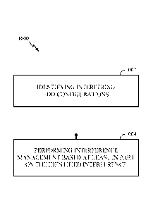
[0091] FIGURE 10 illustrates a method 1000 for mitigating interference in a
wireless
network based on an aspect of the present disclosure.
[0092] In block 1002, an eNodeB identifies interfering TDD configurations. In
one
configuration, the eNodeB may identify the interfering TDD configurations
based on a
downlink signal of a neighboring cNodeB received during an uplink timeslot for
a UE
associated with the eNodeB. In another configuration, the eNodeB may user an
energy
detector for CRS and/or CSI-RS tones to identify the interfering TDD
configuration.
[0093] In block 1004, the eNodeB performs interference management based at
least in
part on the identified interference. In one configuration, the interference
management
may include specifying different scheduling and/or power control for subframes
that are
- 23 -
CA 02869930 2014-10-07
WO 2013/166054 PCT/US2013/038924
mismatched based on the interfering TDD configuration. In another
configuration, the
interference management may include cancelling the downlink signal of the
interfering
eNodeB to detect the uplink signal of the TIE. The downlink signal may
include, for
example, a physical broadcast channel, a CRS, a downlink control channel,
and/or a
shared channel.
[0094] FIGURE 11 illustrates a method 1100 for mitigating interference in a
wireless
network based on an aspect of the present disclosure.
[0095] In block 1102, a UE measures uplink interference in a downlink
subframe. The
interference may be caused by a neighboring UE. In one configuration, the
interference source is the shared channel transmission of the neighboring UE.
[0096] In block 1104, the UE reports the interference to an eNodeB. In one
configuration, after being notified of the interference, the eNodeB may adjust
the
scheduling of the UE. In another configuration, the UE may perform
interference
cancellation on the uplink signal of the neighboring UE. The uplink signal may
be a
shared uplink channel, an uplink control channel, a random access channel,
and/or a
sounding reference signal.
[0097] FIGURE 12 illustrates a method 1200 for mitigating interference in a
wireless
network based on an aspect of the present disclosure.
[0098] In block 1202, an eNodeB defines an anchor set of subframes that are
common
across uplink configurations and downlink configurations. In one
configuration, the
HARQ timing and the ACK/NACK locations for the anchor subframes are not
changed.
100991 In block 1204, the eNodeB defines a non-anchor set of subframes that
are
potentially not common across different uplink configurations and downlink
configurations. In one configuration, the HARQ timing and ACK/NACK locations
for
the non-anchor subframes are changed for adaptive TDD configurations and/or
based on
an interference level. The anchor set of subframes and the non-anchor set of
subframes
may be selected from all possible TDD configurations or only the TDD
configurations
specified for a specific network/system.
[00100] In block 1206, the eNodeB signals one or more of the anchor set,
the
- 24 -
CA 02869930 2014-10-07
WO 2013/166054 PCT/US2013/038924
non-anchor set, or a combination thereof to at least one UE. The signaling may
be SIB
or RRC signaling. The signaling may include detailed TDD configuration
information,
and may be broadcast or unicast as a bitmap or an index value.
1001011 FIGURE 13 is a conceptual data flow diagram illustrating the data
flow
between different modules/means/components in an exemplary apparatus 1300. The
apparatus 1300 includes an interference identifying module 1302 that
identifies
interfering TDD configurations. The interference may result from a mismatch
between
an uplink communication of a first base station and a downlink communication
of a
second base station. The interference identifying module 1302 may receive a
downlink
transmission of an interfering eNodeB during an uplink timeslot of a UE. The
downlink
transmission may be received via the signal 1310 received at the receiving
module
1306. In one configuration, the receiving module 1306 may notify the
interference
identifying module 1302 that the downlink transmission has been received. In
another
configuration, the receiving module 1306 communicates the downlink
transmission to
the interference identifying module 1302.
[00102] The apparatus 1300 also includes an interference management
module
1304 that manages the identified interference. As previously discussed, in one
configuration, the interference management module may specify different
scheduling
and/or power control for subframes that are mismatched based on the
interfering TDD
configuration. In another configuration, the interference management module
may
cancel the downlink signal of the interfering eNodeB to detect the uplink
signal of the
UE. That is, the interference management module 1304 may use the transmission
module 1308 to transmit a signal 1313 to manage the interference. The signal
1313 may
cancel the downlink interference and/or control subframc scheduling and/or
power. The
apparatus may include additional modules that perform each of the steps of the
process
in the aforementioned flow chart of FIGURE 10. As such, each step in the
aforementioned flow chart FIGURE 10 may be performed by a module and the
apparatus may include one or more of those modules. The modules may be one or
more
hardware components specifically configured to carry out the stated
processes/algorithm, implemented by a processor configured to perform the
stated
processes/algorithm, stored within a computer-readable medium for
implementation by
a processor, or some combination thereof
- 25 -
CA 02869930 2014-10-07
WO 2013/166054 PCT/US2013/038924
[00103] FIGURE 14 is a conceptual data flow diagram illustrating the data
flow
between different modules/means/components in an exemplary apparatus 1400. The
apparatus 1400 includes an interference measurement module 1402 that measures
uplink interference in a downlink subframe of the UE. The interference
measurement
module 1402 may receive a downlink transmission of an interfering UE during a
downlink timeslot of a UE. The uplink transmission may be received via the
signal
1410 received at the receiving module 1406. In one configuration, the
receiving module
1406 may notify the interference measurement module 1402 that the uplink
transmission has been received. In another configuration, the receiving module
1406
communicates the uplink transmission received via signal 1410 to the
interference
measurement module 1402.
[00104] The apparatus 1400 also includes an interference reporting module
1404
that reports the identified interference to an eNodeB. Specifically, the
interference
reporting module 1404 may use the transmission module 1408 to transmit a
signal 1412
to report the interference to the eNodeB. The apparatus may include additional
modules
that perform each of the steps of the process in the aforementioned flow chart
of
FIGURE 11. As such, each step in the aforementioned flow chart FIGURE 11 may
be
performed by a module and the apparatus may include one or more of those
modules.
The modules may be one or more hardware components specifically configured to
carry
out the stated processes/algorithm, implemented by a processor configured to
perform
the stated processes/algorithm, stored within a computer-readable medium for
implementation by a processor, or some combination thereof.
[00105] FIGURE 15 is a conceptual data flow diagram illustrating the data
flow
between different modules/means/components in an exemplary apparatus 1500. The
apparatus 1500 includes an anchor subframe defining module 1502 that defines
an
anchor set of subframes that are common across uplink configurations and
downlink
configurations (e.g., TDD configurations). The apparatus 1500 also includes an
non-
anchor subframe defining module 1504 that defines a non-anchor set of
subframes that
are potentially not common across different uplink configurations and downlink
configurations (e.g., TDD configurations).
[00106] The anchor subframe defining module 1502 and/or non-anchor
subframe
defining module 1504 may be informed of the TDD configurations of a specific
network
- 26 -
CA 02869930 2014-10-07
WO 2013/166054 PCT/US2013/038924
based on a signal 1510 received at the receiving module 1506. In one
configuration, the
receiving module 1506 may notify the anchor subframe defining module 1502
and/or
the non-anchor subframe defining module 1504 of the TDD configurations. In
another
configuration, the receiving module 1506 communicates the TDD configurations
received via signal 1510 to the anchor subframe defining module 1502 and/or
the non-
anchor subframe defining module 1504.
[00107] Additionally, the transmission module 1508 may be specified to
transmit
a signal 1512 to signal one or more of the anchor set, and the non-anchor set
to at least
one UE. The transmission module 1508 may be notified of the non-anchor set
and/or
the anchor set directly from each of the anchor subframe defining module 1502
and the
non-anchor subframe defining module 1504. The apparatus may include additional
modules that perform each of the steps of the process in the aforementioned
flow chart
of FIGURE 12. As such, each step in the aforementioned flow chart FIGURE 12
may
be performed by a module and the apparatus may include one or more of those
modules.
The modules may be one or more hardware components specifically configured to
carry
out the stated processes/algorithm, implemented by a processor configured to
perform
the stated processes/algorithm, stored within a computer-readable medium for
implementation by a processor, or some combination thereof.
1001081 FIGURE 16 is a diagram illustrating an example of a hardware
implementation
for an apparatus 1600 employing a processing system 1614. The processing
system
1614 may be implemented with a bus architecture, represented generally by the
bus
1624. The bus 1624 may include any number of interconnecting buses and bridges
depending on the specific application of the processing system 1614 and the
overall
design constraints. The bus 1624 links together various circuits including one
or more
processors and/or hardware modules, represented by the processor 1622 the
modules
1602, 1604 and the computer-readable medium 1626. The bus 1624 may also link
various other circuits such as timing sources, peripherals, voltage
regulators, and power
management circuits, which are well known in the art, and therefore, will not
be
described any further.
[00109] The apparatus includes a processing system 1614 coupled to a
transceiver
1630. The transceiver 1630 is coupled to one or more antennas 1620. The
transceiver
1630 enables communicating with various other apparatus over a transmission
medium.
-27 -
CA 02869930 2014-10-07
WO 2013/166054 PCT/US2013/038924
The processing system 1614 includes a processor 1622 coupled to a computer-
readable
medium 1626. The processor 1622 is responsible for general processing,
including the
execution of software stored on the computer-readable medium 1626. The
software,
when executed by the processor 1622, causes the processing system 1614 to
perform the
various functions described for any particular apparatus. The computer-
readable
medium 1626 may also be used for storing data that is manipulated by the
processor
1622 when executing software.
[00110] The processing system 1614 includes an interference identifying
module
1602 for identifying interfering time division duplexing (TDD) configurations.
The
processing system 1614 also includes an interference management module 1604
for
performing interference management based at least in part on the identified
interference.
The modules may be software modules running in the processor 1622,
resident/stored in
the computer-readable medium 1626, one or more hardware modules coupled to the
processor 1622, or some combination thereof. The processing system 1614 may be
a
component of the UE 650 and may include the memory 660, and/or the
controller/processor 659.
[00111] FIGURE 17 is a diagram illustrating an example of a hardware
implementation
for an apparatus 1700 employing a processing system 1714. The processing
system
1714 may be implemented with a bus architecture, represented generally by the
bus
1724. The bus 1724 may include any number of interconnecting buses and bridges
depending on the specific application of the processing system 1714 and the
overall
design constraints. The bus 1724 links together various circuits including one
or more
processors and/or hardware modules, represented by the processor 1722 the
modules
1702, 1704 and the computer-readable medium 1726. The bus 1724 may also link
various other circuits such as timing sources, peripherals, voltage
regulators, and power
management circuits, which are well known in the art, and therefore, will not
be
described any further.
[00112] The apparatus includes a processing system 1714 coupled to a
transceiver
1730. The transceiver 1730 is coupled to one or more antennas 1720. The
transceiver
1730 enables communicating with various other apparatus over a transmission
medium.
The processing system 1714 includes a processor 1722 coupled to a computer-
readable
medium 1726. The processor 1722 is responsible for general processing,
including the
- 28 -
CA 02869930 2014-10-07
WO 2013/166054 PCT/US2013/038924
execution of software stored on the computer-readable medium 1726. The
software,
when executed by the processor 1722, causes the processing system 1714 to
perform the
various functions described for any particular apparatus. The computer-
readable
medium 1726 may also be used for storing data that is manipulated by the
processor
1722 when executing software.
[00113] The processing system 1714 includes an interference measurement module
1702 for measuring, by a UE, uplink interference in a downlink subframe of the
UE.
The processing system 1714 also includes an interference reporting module 1704
for
reporting the identified interference to an eNodeB. The modules may be
software
modules running in the processor 1722, resident/stored in the computer-
readable
medium 1726, one or more hardware modules coupled to the processor 1722, or
some
combination thereof. The processing system 1714 may be a component of the UE
650
and may include the memory 660, and/or the controller/processor 659.
[00114] FIGURE 18 is a diagram illustrating an example of a hardware
implementation
for an apparatus 1800 employing a processing system 1814. The processing
system
1814 may be implemented with a bus architecture, represented generally by the
bus
1824. The bus 1824 may include any number of interconnecting buses and bridges
depending on the specific application of the processing system 1814 and the
overall
design constraints. The bus 1824 links together various circuits including one
or more
processors and/or hardware modules, represented by the processor 1822 the
modules
1802, 1804, 1806 and the computer-readable medium 1826. The bus 1824 may also
link various other circuits such as timing sources, peripherals, voltage
regulators, and
power management circuits, which are well known in the art, and therefore,
will not be
described any further.
[00115] The apparatus includes a processing system 1814 coupled to a
transceiver
1830. The transceiver 1830 is coupled to one or more antennas 1820. The
transceiver
1830 enables communicating with various other apparatus over a transmission
medium.
The processing system 1814 includes a processor 1822 coupled to a computer-
readable
medium 1826. The processor 1822 is responsible for general processing,
including the
execution of software stored on the computer-readable medium 1826. The
software,
when executed by the processor 1822, causes the processing system 1814 to
perform the
various functions described for any particular apparatus. The computer-
readable
- 29 -
CA 02869930 2014-10-07
WO 2013/166054 PCT/US2013/038924
medium 1826 may also be used for storing data that is manipulated by the
processor
1822 when executing software.
1001161 The processing system 1814 includes an anchor subframe defining module
1802 for defining an anchor set of subframes that are common across a
plurality of
uplink configurations and downlink configurations. The processing system 1814
also
includes a non-anchor subframe defining module 1804 for defining a non-anchor
set of
subframes that are potentially not common across different uplink
configurations and
downlink configurations. The processing system 1814 may further include an
anchor
set signaling module 1806 for signaling one or more of the anchor set, the non-
anchor
set, or a combination thereof to at least one UE. The modules may be software
modules
running in the processor 1822, resident/stored in the computer-readable medium
1826,
one or more hardware modules coupled to the processor 1822, or some
combination
thereof. The processing system 1814 may be a component of the UE 650 and may
include the memory 660, and/or the controller/processor 659.
[00117] In one configuration, the eNodeB 610 is configured for wireless
communication including means for identifying interference. In one
configuration, the
interference identifying means may be the controller/processor 675, memory
676,
receive processor 670, demodulators 618, and/or antenna 620, configured to
perform the
functions recited by the interference identifying means. The eNodeB 610 is
also
configured to include a means for managing the interference. In one aspect,
the
interference management means may be the controller/processor 675, memory 676,
transmit processor 616, modulators 618, and/or antenna 620 configured to
perform the
functions recited by the interference management means. In another
configuration, the
aforementioned means may be any module or any apparatus configured to perform
the
functions recited by the aforementioned means.
[00118] In one configuration, the UE 650 is configured for wireless
communication
including means for measuring interference. In one aspect, the interference
measuring
means may be the controller/processor 659, memory 660, receive processor 656,
modulators 654, and/or antenna 652 configured to perform the functions recited
by the
interference measuring means. The UE 650 is also configured for wireless
communication including means for reporting the measured interference. In one
configuration, the interference reporting means may be the
controller/processor 659,
- 30 -
CA 02869930 2014-10-07
WO 2013/166054 PCT/US2013/038924
memory 660, modulators 654, antenna 652, and/or transmit processor 668
configured to
perform the functions recited by the interference reporting means. In another
configuration, the aforementioned means may be any module or any apparatus
configured to perform the functions recited by the aforementioned means.
1001191 In one configuration, the eNodeB 610 is configured for wireless
communication including means for defining anchor subframe sets and non-anchor
subframes sets. In one configuration, the anchor subframe set and non-anchor
subframes set defining means may be the controller/processor 675, memory 646,
receive
processor 670, demodulators 618, and/or antenna 620 configured to perform the
functions recited by the anchor subframe set and non-anchor subframes set
defining.
The eNodeB 610 is also configured to include a means for signaling the anchor
subframe sets and/or non-anchor subframe sets. In one aspect, the anchor
subframe set
and/or non-anchor subframe set signaling means may be the controller/processor
675,
memory 646, transmit processor 616, modulators 618, and/or antenna 620
configured to
perform the functions recited by the anchor subframe set and/or non-anchor
subframe
set signaling means. In another configuration, the aforementioned means may be
any
module or any apparatus configured to perform the functions recited by the
aforementioned means.
1001201 Those of skill would further appreciate that the various illustrative
logical
blocks, modules, circuits, and algorithm steps described in connection with
the
disclosure herein may be implemented as electronic hardware, computer
software, or
combinations of both. To clearly illustrate this interchangeability of
hardware and
software, various illustrative components, blocks, modules, circuits, and
steps have been
described above generally in terms of their functionality. Whether such
functionality is
implemented as hardware or software depends upon the particular application
and
design constraints imposed on the overall system. Skilled artisans may
implement the
described functionality in varying ways for each particular application, but
such
implementation decisions should not be interpreted as causing a departure from
the
scope of the present disclosure.
[00121] For purposes of disclosure, combinations such as "at least one of A,
B, or C,"
"at least one of A, B, and C," and "A, B, C, or any combination thereof"
include any
combination of A, B, and/or C, and may include multiples of A, multiples of B,
or
- 31 -
CA 02869930 2014-10-07
WO 2013/166054 PCT/US2013/038924
multiples of C. Specifically, combinations such as "at least one of A, B, or
C," "at least
one of A, B, and C," and "A, B, C, or any combination thereof" may be A only,
B only,
C only, A and B, A and C, B and C, or A and B and C, where any such
combinations
may contain one or more member or members of A, B, or C.
1001221 The various illustrative logical blocks, modules, and circuits
described in
connection with the disclosure herein may be implemented or performed with a
general-
purpose processor, a digital signal processor (DSP), an application specific
integrated
circuit (ASIC), a field programmable gate array (FPGA) or other programmable
logic
device, discrete gate or transistor logic, discrete hardware components, or
any
combination thereof designed to perform the functions described herein. A
general-
purpose processor may be a microprocessor, but in the alternative, the
processor may be
any conventional processor, controller, microcontroller, or state machine. A
processor
may also be implemented as a combination of computing devices, e.g., a
combination of
a DSP and a microprocessor, a plurality of microprocessors, one or more
microprocessors in conjunction with a DSP core, or any other such
configuration.
[00123] The steps of a method or algorithm described in connection with the
disclosure
herein may be embodied directly in hardware, in a software module executed by
a
processor, or in a combination of the two. A software module may reside in RAM
memory, flash memory, ROM memory, EPROM memory, EEPROM memory,
registers, hard disk, a removable disk, a CD-ROM, or any other form of storage
medium
known in the art. An exemplary storage medium is coupled to the processor such
that
the processor can read information from, and write information to, the storage
medium.
In the alternative, the storage medium may be integral to the processor. The
processor
and the storage medium may reside in an ASIC. The ASIC may reside in a user
terminal. In the alternative, the processor and the storage medium may reside
as
discrete components in a user terminal.
[00124] In one or more exemplary designs, the functions described may be
implemented in hardware, software, firmware, or any combination thereof. If
implemented in software, the functions may be stored on or transmitted over as
one or
more instructions or code on a computer-readable medium. Computer-readable
media
includes both computer storage media and communication media including any
medium
that facilitates transfer of a computer program from one place to another. A
storage
- 32 -
CA 02869930 2014-10-07
WO 2013/166054 PCT/US2013/038924
media may be any available media that can be accessed by a general purpose or
special
purpose computer. By way of example, and not limitation, such computer-
readable
media can comprise RAM, ROM, EEPROM, CD-ROM or other optical disk storage,
magnetic disk storage or other magnetic storage devices, or any other medium
that can
be used to carry or store desired program code means in the form of
instructions or data
structures and that can be accessed by a general-purpose or special-purpose
computer,
or a general-purpose or special-purpose processor. Also, any connection is
properly
termed a computer-readable medium. For example, if the software is transmitted
from a
website, server, or other remote source using a coaxial cable, fiber optic
cable, twisted
pair, digital subscriber line (DSL), or wireless technologies such as
infrared, radio, and
microwave, then the coaxial cable, fiber optic cable, twisted pair, DSL, or
wireless
technologies such as infrared, radio, and microwave are included in the
definition of
medium. Disk and disc, as used herein, includes compact disc (CD), laser disc,
optical
disc, digital versatile disc (DVD), floppy disk and blu-ray disc where disks
usually
reproduce data magnetically, while discs reproduce data optically with lasers.
Combinations of the above should also be included within the scope of computer-
readable media.
1001251 The previous description of the disclosure is provided to enable any
person
skilled in the art to make or use the disclosure. Various modifications to the
disclosure
will be readily apparent to those skilled in the art, and the generic
principles defined
herein may be applied to other variations without departing from the spirit or
scope of
the disclosure. Thus, the disclosure is not intended to be limited to the
examples and
designs described herein but is to be accorded the widest scope consistent
with the
principles and novel features disclosed herein.
- 33 -