Sélection de la langue

Search

Sommaire du brevet 2871367 

Énoncé de désistement de responsabilité concernant l'information provenant de tiers

Une partie des informations de ce site Web a été fournie par des sources externes. Le gouvernement du Canada n'assume aucune responsabilité concernant la précision, l'actualité ou la fiabilité des informations fournies par les sources externes. Les utilisateurs qui désirent employer cette information devraient consulter directement la source des informations. Le contenu fourni par les sources externes n'est pas assujetti aux exigences sur les langues officielles, la protection des renseignements personnels et l'accessibilité.

Disponibilité de l'Abrégé et des Revendications

L'apparition de différences dans le texte et l'image des Revendications et de l'Abrégé dépend du moment auquel le document est publié. Les textes des Revendications et de l'Abrégé sont affichés :

  • lorsque la demande peut être examinée par le public;
  • lorsque le brevet est émis (délivrance).
(12) Demande de brevet: (11) CA 2871367
(54) Titre français: DISPOSITIF D'ENTREE D'ORDINATEUR A ACTIONNEMENT PNEUMATIQUE
(54) Titre anglais: PNEUMATICALLY ACTUATED COMPUTER INPUT DEVICE
Statut: Réputée abandonnée et au-delà du délai pour le rétablissement - en attente de la réponse à l’avis de communication rejetée
Données bibliographiques
(51) Classification internationale des brevets (CIB):
  • G06F 03/01 (2006.01)
  • A61B 01/247 (2006.01)
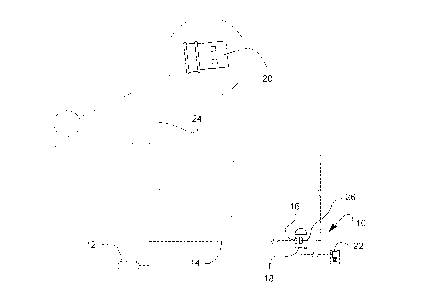
  • A61C 19/00 (2006.01)
  • G05G 01/30 (2009.01)
(72) Inventeurs :
  • K-LAFLAMME, ERIC (Canada)
(73) Titulaires :
  • ERIC K-LAFLAMME
(71) Demandeurs :
  • ERIC K-LAFLAMME (Canada)
(74) Agent:
(74) Co-agent:
(45) Délivré:
(22) Date de dépôt: 2014-11-14
(41) Mise à la disponibilité du public: 2015-05-15
Licence disponible: S.O.
Cédé au domaine public: S.O.
(25) Langue des documents déposés: Anglais

Traité de coopération en matière de brevets (PCT): Non

(30) Données de priorité de la demande:
Numéro de la demande Pays / territoire Date
1320238.7 (Royaume-Uni) 2013-11-15

Abrégés

Abrégé anglais


A pneumatically actuated computer input device comprises an input device
circuit member
having a hollow body, at least one switch member within the hollow body
adapted to send
electronic signals to a computer terminal, and a pneumatic actuator within the
hollow body
adapted to be inflated and press against and activate the at least one switch
member. A
pneumatic hose connected at a distal end to the pneumatic actuator and
extending outward
from the hollow body at a predetermined length and adapted to supply air
thereto, and a foot
pedal connected to the pneumatic hose at an opposite end from the distal end
and adapted to
control the air supply through the pneumatic hose and to the pneumatic
actuator, such that
when the foot pedal is pressed the pneumatic actuator is filled with air,
expands, and presses
against the at least one switch member which then sends an electronic signal
to the computer
terminal.

Revendications

Note : Les revendications sont présentées dans la langue officielle dans laquelle elles ont été soumises.


CLAIMS
1.) A pneumatically actuated computer input device comprising an
input device circuit member having a hollow body, at least one switch
member within said hollow body adapted to send electronic signals to
a computer terminal, and a pneumatic actuator within said hollow body
adapted to be inflated and press against and activate said at least one
switch member; a pneumatic hose connected at a distal end to said
pneumatic actuator and extending outward from said hollow body at a
predetermined length and adapted to supply air thereto; and a foot
pedal connected to said pneumatic hose at an opposite end from said
distal end and adapted to control said air supply through said
pneumatic hose and to said pneumatic actuator, such that when said
foot pedal is pressed the pneumatic actuator is filled with air, expands,
and presses against said at least one switch member which then
sends an electronic signal to said computer terminal.
2.) The pneumatically actuated computer input of claim 1, further
comprising a power source to provide electricity to said input device
circuit member, which is then used to send said electronic signals.
3.) The pneumatically actuated computer input of claim 2, wherein said
power source is formed as an AC (alternating current) power source.
4.) The pneumatically actuated computer input of claim 2, wherein said
power source comprises a battery member.
5.) The pneumatically actuated computer input of claim 1, wherein said
input device circuit member further comprises an electrical wire
connected to said at least one switch member and is adapted to

connect with said computer terminal, to thereby send electronic
signals to said computer terminal.
6.) The pneumatically actuated computer input of claim 1, further
comprising a signal receiver adapted to be connected to said
computer terminal; and wherein said input device circuit member
further comprises a signal transmitter connected to said at least one
switch member that is adapted to wirelessly connect with said signal
receiver on said computer terminal, to thereby wirelessly send
electronic signals to said computer terminal.
7.) The pneumatically actuated computer input of claim 1, wherein
said pneumatic hose is a pass through having an entry point into said
input device different than an exit point.
8.) A pneumatically actuated computer device comprising a computer
terminal and a pneumatically actuated computer input device, said
pneumatically actuated computer input device comprising an input
device circuit member having a hollow body, at least one switch
member within said hollow body adapted to send electronic signals to
said computer terminal, and a pneumatic actuator within said hollow
body adapted to be inflated and press against and activate said at
least one switch member; a pneumatic hose connected at a distal end
to said pneumatic actuator and extending outward from said hollow
body at a predetermined length and adapted to supply air thereto; and
a foot pedal connected to said pneumatic hose at an opposite end
from said distal end and adapted to control said air supply through
said pneumatic hose and to said pneumatic actuator, such that when
said foot pedal is pressed the pneumatic actuator is filled with air,
expands, and presses against said at least one switch member which
then sends an electronic signal to said computer terminal.

9.) The pneumatically actuated computer input of claim 8, further
comprising a power source to provide electricity to said input device
circuit member, which is then used to send said electronic signals.
10.) The pneumatically actuated computer input of claim 9, wherein
said power source is formed as an AC (alternating current) power
source.
11.) The pneumatically actuated computer input of claim 9, wherein
said power source comprises a battery member.
12.) The pneumatically actuated computer input of claim 8, wherein
said input device circuit member further comprises an electrical wire
connected between said at least one switch member and said
computer terminal, to thereby send electronic signals to said computer
terminal.
13.) The pneumatically actuated computer input of claim 8, further
comprising a signal receiver connected to said computer terminal; and
wherein said input device circuit member further comprises a signal
transmitter connected to said at least one switch member that is
adapted to wirelessly connect with said signal receiver on said
computer terminal, to thereby wirelessly send electronic signals to said
computer terminal.
14.) The pneumatically actuated computer input of claim 8, wherein
said pneumatic hose is a pass through having an entry point into said
input device different than an exit point.

Description

Note : Les descriptions sont présentées dans la langue officielle dans laquelle elles ont été soumises.

CA 02871367 2014-11-14
Pneumatically actuated computer input device
FIELD OF THE INVENTION
[001] The present invention relates generally to computer input interface but
more particularly to a pneumatically actuated computer input device.
BACKGROUND OF THE INVENTION
[002] Dentists rely increasingly on the use of computers in their practice. It
can be for imagery purposes such as taking photos or videos of a
patient's mouth, for example. The problem is in how to computer can be
made to do an action while the dentist has his hands busy without
having to add a second pneumatic or electronic pedal, as each added
piece of equipment makes keeping the room aseptic more complicated.
SUMMARY OF THE INVENTION
[003] It is a main advantage of this invention to provide for an easy way for
a
dentist to operate a computer input device such as a mouse or game
port device that is used for controlling various devices such as an intra
oral camera by simply using a foot pedal which controls the flow of a
pneumatic hose. The air pressure presses down on a switch on a
computer input device circuit. Pneumatic pedals are well known in the
art of dentistry and controlling a switch using air makes it easy for

CA 02871367 2014-11-14
dentists to learn how to use the device. Generally, dentists use a foot
pedal to actuate certain tools such as a pneumatic drill for example. The
response to a switch can be programmed by existing software. For
example, a click can actuate a macro that opens a video application. A
double click can actuate another macro. These macros can be re-
initialised quickly by redefining the action that a click (or double click, or
click and hold) can do so as to allow pre defined functions depending on
the task to be performed on a specific patient.
[004] Each press on the pedal that controls the pneumatic hose presses on a
switch which sends a signal is sent to the computer. If the computer
software is in "stop" mode, the signal will have no effect. When the
software is "on", each received signal effects a function. For example, if
a dentist wants to use a drill while at the same time taking pictures with
an intra oral camera, all he has to do is put the software on and each
time he stops and restarts the drill, by releasing and pressing the pedal,
a picture is taken (or a video clip). The dentist does not have to choose
with a pedal click if he will use the drill or any other air instrument, since
each pedal click is sent to the computer no matter what he wants to do.
If no other action programmed in the computer is needed, all the dentist
has to do is to put the software in "off' (or pause, stop).

CA 02871367 2014-11-14
[005] In order to do so, the invention comprises an input device circuit
member having a hollow body, at least one switch member within the
hollow body adapted to send electronic signals to a computer terminal,
and a pneumatic actuator within the hollow body adapted to be inflated
and press against and activate the at least one switch member. A
pneumatic hose connected at a distal end to the pneumatic actuator and
extending outward from the hollow body at a predetermined length and
adapted to supply air thereto, and a foot pedal connected to the
pneumatic hose at an opposite end from the distal end and adapted to
control the air supply through the pneumatic hose and to the pneumatic
actuator, such that when the foot pedal is pressed the pneumatic
actuator is filled with air, expands, and presses against the at least one
switch member which then sends an electronic signal to the computer
terminal.
15[006] The pneumatically actuated computer further comprises a power source
to provide electricity to the input device circuit member, which is then
used to send the electronic signals.
[007] The pneumatically actuated computer has the power source formed as
an AC (alternating current) power source.
20[008] The pneumatically actuated computer has the power source comprising
battery member.

CA 02871367 2014-11-14
[009] The pneumatically actuated computer input has the input device circuit
member further comprising an electrical wire connected to the at least
one switch member and is adapted to connect with the computer
terminal, to thereby send electronic signals to the computer terminal.
5[0010] The pneumatically actuated computer input is further comprised of a
signal receiver adapted to be connected to the computer terminal, and
the input device circuit member id further comprised of a signal
transmitter connected to the at least one switch member that is adapted
to wirelessly connect with the signal receiver on the computer terminal,
to thereby wirelessly send electronic signals to the computer terminal.
[0011] The pneumatically actuated computer input has the pneumatic hose
being pass through so as to have an entry point into the input device
different than an exit point.
[0012] The pneumatically actuated computer device is comprised of a
computer terminal and a pneumatically actuated computer input device.
Since pneumatically actuated triggers (pedals) are known in the art and
that the circuitry of an input device for a computer is also known in the
art, no discussion about these components is given since they are
known in different arts.

CA 02871367 2014-11-14
[0013] There has thus been outlined, rather broadly, the more important
features of the invention in order that the detailed description thereof
that follows may be better understood, and in order that the present
contribution to the art may be better appreciated. There are additional
features of the invention that will be described hereinafter and which will
form the subject matter of the claims appended hereto.
[0014] In this respect, before explaining at least one embodiment of the
invention in detail, it is to be understood that the invention is not limited
in its application to the details of construction and to the arrangements
of the components set forth in the following description or illustrated in
the drawings. The invention is capable of other embodiments and of
being practiced and carried out in various ways.
[0015] Also, it is to be understood that the phraseology and terminology
employed herein are for the purpose of description and should not be
regarded as limiting. As such, those skilled in the art will appreciate that
the conception, upon which this disclosure is based, may readily be
utilized as a basis for the designing of other structures, methods and
systems for carrying out the several purposes of the present invention.
For example, although described primarily as a tool for dentists, it
should be understood that such a device can be used by other
professionals or artisans. Such a device could also be used by people
having reduced mobility. It is important, therefore, that the claims be

CA 02871367 2014-11-14
regarded as including such equivalent constructions insofar as they do
not depart from the spirit and scope of the present invention.
[0016] These together with other objects of the invention, along with the
various
features of novelty which characterize the invention, are pointed out with
particularity in the claims annexed to and forming a part of this
disclosure. For a better understanding of the invention, its operating
advantages and the specific objects attained by its uses, reference
should be made to the accompanying drawings and descriptive matter
which contains illustrated preferred embodiments of the invention.
BRIEF DESCRIPTION OF THE DRAWINGS
[0017] Fig. 1 Side elevation of the invention in context of use.
15[0018] Fig. 2 Side elevation of the invention in context of use with an
alternate
air hose configuration.
[0019] Fig. 3 Top view of the invention.
[0020] Figs. 4a-b Top views of an input device with micro switch.

CA 02871367 2014-11-14
[0021] Fig. 5a Top view of a variant of the input device wherein the air hose
has an entry and an exit point.
DETAILED DESCRIPTION
[0022] A pneumatically actuated computer input device (10) is actuated by a
foot pedal (12). The foot pedal (12) itself controls the flow of pressurized
air inside a pneumatic hose (14). The pressure inflates a pneumatic
actuator (16) which then presses down on a switch member (26) located
on the input device circuit member (18). Once a click is made (or any
combination thereof), the rest works like a usual input device click ¨
including macros -- whether the input device circuit (18) is wireless, --in
which case a signal receiver (20) connected to a computer (24), or
keyboard (25) is required -- or wire based (not shown). The input device
circuit member (18) is generally connected to a power source such as
an AC source (22) for example, or a DC source such as a battery
member (26), for example. The input device circuit member (18) also
comprises a signal transmitter (21) to communicate with the signal
receiver (20).
[0023] Fig. 5 shows a variant, the input device member (18) wherein the
pneumatic hose (14) is a pass through hose having an entry point into
the input device (10) different than the exit point so as to operate
another device such as those available in the dentistry industry.

Dessin représentatif
Une figure unique qui représente un dessin illustrant l'invention.
États administratifs

2024-08-01 : Dans le cadre de la transition vers les Brevets de nouvelle génération (BNG), la base de données sur les brevets canadiens (BDBC) contient désormais un Historique d'événement plus détaillé, qui reproduit le Journal des événements de notre nouvelle solution interne.

Veuillez noter que les événements débutant par « Inactive : » se réfèrent à des événements qui ne sont plus utilisés dans notre nouvelle solution interne.

Pour une meilleure compréhension de l'état de la demande ou brevet qui figure sur cette page, la rubrique Mise en garde , et les descriptions de Brevet , Historique d'événement , Taxes périodiques et Historique des paiements devraient être consultées.

Historique d'événement

Description Date
Demande non rétablie avant l'échéance 2019-11-14
Le délai pour l'annulation est expiré 2019-11-14
Lettre envoyée 2019-11-14
Représentant commun nommé 2019-10-30
Réputée abandonnée - omission de répondre à un avis sur les taxes pour le maintien en état 2018-11-14
Requête visant le maintien en état reçue 2017-09-21
Requête visant le maintien en état reçue 2016-10-13
Inactive : Page couverture publiée 2015-05-25
Demande publiée (accessible au public) 2015-05-15
Inactive : CIB attribuée 2014-11-28
Inactive : CIB attribuée 2014-11-26
Inactive : CIB en 1re position 2014-11-26
Inactive : CIB attribuée 2014-11-26
Inactive : Certificat dépôt - Aucune RE (bilingue) 2014-11-25
Demande reçue - nationale ordinaire 2014-11-21
Inactive : CQ images - Numérisation 2014-11-14
Déclaration du statut de petite entité jugée conforme 2014-11-14
Inactive : Pré-classement 2014-11-14

Historique d'abandonnement

Date d'abandonnement Raison Date de rétablissement
2018-11-14

Taxes périodiques

Le dernier paiement a été reçu le 2017-09-21

Avis : Si le paiement en totalité n'a pas été reçu au plus tard à la date indiquée, une taxe supplémentaire peut être imposée, soit une des taxes suivantes :

  • taxe de rétablissement ;
  • taxe pour paiement en souffrance ; ou
  • taxe additionnelle pour le renversement d'une péremption réputée.

Les taxes sur les brevets sont ajustées au 1er janvier de chaque année. Les montants ci-dessus sont les montants actuels s'ils sont reçus au plus tard le 31 décembre de l'année en cours.
Veuillez vous référer à la page web des taxes sur les brevets de l'OPIC pour voir tous les montants actuels des taxes.

Historique des taxes

Type de taxes Anniversaire Échéance Date payée
Taxe pour le dépôt - petite 2014-11-14
TM (demande, 2e anniv.) - petite 02 2016-11-14 2016-10-13
TM (demande, 3e anniv.) - petite 03 2017-11-14 2017-09-21
Titulaires au dossier

Les titulaires actuels et antérieures au dossier sont affichés en ordre alphabétique.

Titulaires actuels au dossier
ERIC K-LAFLAMME
Titulaires antérieures au dossier
S.O.
Les propriétaires antérieurs qui ne figurent pas dans la liste des « Propriétaires au dossier » apparaîtront dans d'autres documents au dossier.
Documents

Pour visionner les fichiers sélectionnés, entrer le code reCAPTCHA :


Pour visualiser une image, cliquer sur un lien dans la colonne description du document. Pour télécharger l'image (les images), cliquer l'une ou plusieurs cases à cocher dans la première colonne et ensuite cliquer sur le bouton "Télécharger sélection en format PDF (archive Zip)" ou le bouton "Télécharger sélection (en un fichier PDF fusionné)".

Liste des documents de brevet publiés et non publiés sur la BDBC .

Si vous avez des difficultés à accéder au contenu, veuillez communiquer avec le Centre de services à la clientèle au 1-866-997-1936, ou envoyer un courriel au Centre de service à la clientèle de l'OPIC.


Description du
Document 
Date
(aaaa-mm-jj) 
Nombre de pages   Taille de l'image (Ko) 
Dessin représentatif 2015-04-16 1 17
Description 2014-11-13 7 194
Abrégé 2014-11-13 1 22
Revendications 2014-11-13 3 103
Dessins 2014-11-13 5 106
Certificat de dépôt 2014-11-24 1 177
Avis de rappel: Taxes de maintien 2016-08-15 1 120
Courtoisie - Lettre d'abandon (taxe de maintien en état) 2018-12-26 1 177
Avis de rappel: Taxes de maintien 2017-08-14 1 128
Avis de rappel: Taxes de maintien 2018-08-14 1 120
Deuxième avis de rappel: taxes de maintien 2019-05-14 1 130
Rappel - requête d'examen 2019-07-15 1 123
Avis de rappel: Taxes de maintien 2019-08-14 1 120
Avis du commissaire - Requête d'examen non faite 2019-12-04 1 536
Avis du commissaire - non-paiement de la taxe de maintien en état pour une demande de brevet 2019-12-26 1 533
Paiement de taxe périodique 2016-10-12 1 24
Paiement de taxe périodique 2017-09-20 1 25