Note : Les descriptions sont présentées dans la langue officielle dans laquelle elles ont été soumises.
CA 02872441 2014-11-24
LOCKNUT WITH CAGE
BACKGROUND OF THE INVENTION
[0001] The present invention relates to locknuts, and more particularly to
locknuts
that include a locking coil.
[0002] Locknuts can include a locking coil, such as a spring coil or a
spring band, as
a locking element. In the tightening direction, the nut creates compression on
the locking
coil, which causes the coil to loosen its grip on the threaded member to
permit relative
rotation. In the loosening direction, the nut creates tension on the locking
coil, which causes
the coil to tighten its grip on the threaded member to prevent unintended
relative rotation (i.e.
loosening).
[0003] Locknuts having locking coils are disclosed in U.S. Patents
8,021,093 issued
September 20, 2011; 8,425,168 issued April 23, 2013; and 8,439,616 issued May
14, 2013,
all to Campau, and in U.S. Patent Application 13/359,942 filed January 27,
2012 by Campau.
These locknuts include nut bodies that must be machined, for example to form
slots,
passages, and notches in the nut body to receive the tangs of the locking
coil. Such
machining can be difficult, labor-intensive, and expensive.
SUMMARY OF THE INVENTION
[0004] The aforementioned problems are overcome in the present invention in
which
a cage is included in the fastener. The cage reduces the amount of machining
required on the
fastener body, and thereby reduces the cost of manufacturing the fastener.
[0005] As disclosed, the locking fastener includes a fastener body, a
locking coil, and
a cage. The locking coil is located within the cage, and the cage is secured
within the
fastener body. The cage includes first and second stops, and the locking coil
includes first
and second tangs proximate the first and second stops. The tangs are
positioned to engage
the stops when the nut body is rotated, so that the coil is loosened when the
fastener body is
turned in a first direction and tightened with the fastener body is turned in
a second direction.
[0006] These and other advantages and features of the invention will be
more fully
understood and appreciated by reference to the description of the current
embodiments and
the drawings.
BRIEF DESCRIPTION OF THE DRAWINGS
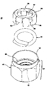
[0007] Fig. 1 is a perspective, exploded view of the current embodiment of
the
locknut;
CA 02872441 2014-11-24
[0008] Fig. 2 is a top perspective view of the body of the locknut;
[0009] Fig. 3 is top view of the locking band of the locknut;
[00010] Fig. 4 is a bottom perspective view of the cage of the locknut;
[00011] Fig. 5 is a bottom perspective view of the cage and locking band of
the
locknut;
[00012] Fig. 6 is a bottom perspective view of the cage and the locking
band
illustrating the deformation of the lower edge of the cage for capturing the
locking band;
[00013] Fig. 7 schematically depicts steps A-E of the assembly of the
locknut; and
[00014] Fig. 8 is a cross-sectional view of the locknut, taken along line
VIII-VIII of
Fig. 7.
DESCRIPTION OF THE CURRENT EMBODIMENT
[00015] Before the current embodiment of the invention is described, it is
pointed out
that the invention is not limited to the details of operation, the details of
construction, or the
arrangement of the components set forth in the following description or
illustrated in the
drawings. The invention may be implemented in various other embodiments and
may be
practiced or carried out in alternative ways not expressly disclosed herein.
Also, it is pointed
out that the terminology used herein is for the purpose of description and
should not be
regarded as limiting. The use of "including" and "comprising" and variations
thereof
encompasses the items listed thereafter and equivalents thereof as well as
additional items
and equivalents thereof Further, enumeration may be used in the description of
various
embodiments. Unless otherwise expressly stated, the use of enumeration should
not be
construed as limiting the invention to any specific order or number of
components. Nor
should the use of enumeration be construed as excluding from the scope of the
invention any
additional steps or components that might be combined with or into the
enumerated steps or
components.
[00016] A locknut constructed in accordance with one embodiment of the
invention is
illustrated in Figs. 1-8 and generally designated 40. Though shown in Figs. 1-
8 as a retaining
nut or a locknut, the concepts of the present invention can be incorporated
into a variety of
fasteners as will be recognized by those skilled in the art.
[00017] The locknut 40 includes a fastener body 42, a locking coil,
element, spring, or
band 44, and a cage 80. The fastener body 42 includes a hex-shaped outer
portion 46
configured to be engaged and driven by a conventional driving tool (not
shown). The hex-
shaped portion 46 includes a plurality of corners 48 and a plurality of flats
50 extending
therebetween. Alternatively, the fastener body 42 may be square, otherwise
polygonal, or
- 2 -
CA 02872441 2014-11-24
any other shape. The fastener body 42 may also be shaped to be engaged by any
conventional driving tool, now known or later developed.
[00018] The fastener body 42 defines a bore 52, which is at least partially
threaded
along its length. As shown in Fig. 2, the bore 52 includes a first portion 54
that is threaded
and a second portion, pocket, recess, or counterbore 56 that is unthreaded.
The diameter of
the unthreaded portion 56 is greater than the diameter of the threaded portion
54 and a
shoulder 60 separates the first and second portions 54, 56.
[00019] Referring now to Fig. 3, the locking band 44 includes a coil or
continuously
curved portion 70 having a circular cross-section extending between a first
tang or end
portion 72 and a second tang or end portion 74. Though illustrated with a
circular cross-
section, other cross-sectional shapes are contemplated including square,
rectangular, oval,
triangular, and any other suitable shape.
[00020] In the illustrated example, the first and second tangs or end
portions 72, 74 are
straight, but other shapes, including smooth curves and angles, are also
contemplated. Both
tangs 72, 74 extend tangentially outward from the curved portion 70. Also, the
locking band
44 may include a single turn, with the first tang 72 overlapping the second
tang 74. The
locking band 44 may alternatively include less than a single turn, or two or
more helical turns
so that adjacent turns are substantially in contact with each other. If the
locking band 44
includes less than a single turn, the locking band 44 may extend entirely
within a single plane
oriented perpendicularly to the bore 52, or may extend helically. As shown in
Fig. 3, the
locking band 44 may be symmetrical to simplify manufacturing.
[00021] Referring now to Figs. 4-6, the locknut 40 also includes a spring
retainer or
cage 80. The cage 80 is a generally cup-shaped element having a rim 84 that
defines a
central opening 82 in an upper surface of the cage 80. The cage 80 further
includes a skirt or
circumferential wall. As illustrated, the skirt is formed by a plurality of
projections or tabs 86
separated by a plurality of slots, spaces, or openings 88, each tab 86
defining two side edges
or stops 90. Further, at least two of the tabs can be truncated tabs 92. The
truncated tabs 92
are shorter than the tabs 86.
[00022] The cage 80 may be manufactured of a flat metal that is formed in a
progressive stamping operation or any other suitable material or forming
operation. It should
be noted that while the illustrated example shows eight spaces 88 between the
tabs 86, 92,
more or fewer spaces 88 are contemplated. As will be described hereinafter,
some of the
spaces 88 are included for reasons of functionality for the locknut 40, while
others are
included for reasons of manufacturability of the cage 80. Additionally, the
cage 80 with its
- 3 -
CA 02872441 2014-11-24
plurality of tabs 86, 92 may be rotationally symmetrical about its central
axis to simplify
manufacturing and assembly thereof.
[00023] The locking band 44 is located within the cage 80 and is oriented
such that the
tangentially-extending first tang 72 is positioned beneath the truncated tab
92, as shown in
the orientation of Fig. 1, and may extend into the space 88. An end of the
second tang 74 is
positioned within the space 88. As can be seen in Fig. 5, angular movement of
the first and
second tangs 72, 74 is therefore constrained by the side edges 90 of the
adjacent tabs 86,
which act as stops. For example, during rotation of the fastener body 42 in an
installation or
clockwise direction, the end of the second tang 74 may contact side edge 90 of
the adjacent
tab 86, and in a removal or counterclockwise direction, the end of the first
tang 72 may
contact side edge 90 of the adjacent tab 86. Accordingly, the angular movement
of the first
and second tangs 72, 74 is limited relative to the fastener body 42. The
curved portion 70 of
the locking band 44 rests upon the interior surface of the rim 84. When the
locking band 44
is installed in the cage 80, a lower edge of one or more of the tabs 86 may be
locally
deformed, as illustrated in Fig. 6, to capture the locking band 44 and create
a subassembly for
subsequent installation in the locknut 40.
[00024] Both the cage 80 and the locking band 44 may be sized to fit the
desired
fastener body 42 and externally threaded member 45. As can be seen in Fig. 8,
the outside
diameter of the cage 80 may be selected to closely fit within the internal
diameter of the
collar 56, and the central opening 82 may be selected to match the inner
diameter of the
threaded first portion 54 of the fastener body 42. The diameter of the locking
band 44 may
be sized to fit within the cage 80, but includes sufficient clearance to
enable the locking band
44 to expand when the locknut 40 is mounted to the externally threaded member
45. Further,
the diameter of the circular cross-section of the locking band 44 generally
corresponds to the
pitch of the threaded member 45, such that the locking band 44 fits within the
threads of the
threaded member 45. In a locking band with a non-circular cross-section, the
dimension of
the surface engaging the threads of the threaded member 45 may be less than,
generally the
same as, or greater than the pitch of the threaded member.
[00025] The fastener body 42, locking band 44, and cage 80 may be
manufactured
from any suitable materials, including metals and composites. Additionally,
the locking band
44 may be manufactured from relatively low-cost materials such as round steel
wire.
[00026] Referring back now to Fig. 7, the assembly of the locknut 40 will
be described
in steps A-E. In step A, the fastener body 42 is spun or threaded onto a
threaded post 100,
leaving a portion of the post 100 extending beyond the fastener body 42. The
cage 80 and
locking band 44 sub-assembly is threaded, in step B, onto the post 100, above
the fastener
- 4 -
CA 02872441 2014-11-24
body 42, and then the fastener body 42 is rotated toward the cage 80 in step
C. The cage 80
and locking band 44 sub-assembly remains stationary on the post 100 while the
fastener body
42 draws closer, until the shoulder 60 of the fastener body 42 bottoms out on
the lower
surface of the cage 80 tabs 86. In this position of step C, the cage 80 and
locking band 44
sub-assembly and the fastener body 42 are now indexed and aligned.
[00027] To retain the cage 80 and locking band 44 sub-assembly within the
fastener
body 42 and to maintain alignment of the components, the collar 56 of the
fastener body 42
may be controllably deformed, as in step D. It is contemplated that
manufacturing methods
such as swaging, crimping, or orbital forming may be utilized. Of course, any
other suitable
means for bending the collar 56 over the cage 80 may also be used. Once the
collar 56 is
deformed, the locknut 40 is complete and may be rotated off the post 100, as
in step E.
[00028] Installing the fastener body 42, the cage 80, and locking band 44
onto the post
100 aligns the components such that the threads of the fastener body 42 and
the helical coil of
the locking band 44 are indexed and may be mounted to the externally threaded
member 45.
For proper performance of the completed locknut 40, the cage 80 and locking
band 44 sub-
assembly must not rotate relative the fastener body 42. Accordingly, the rim
84 of the cage
80 may include knurling or notches, to enhance engagement with the deformed
collar 56.
[00029] Installation of the locknut 40 in a first or generally clockwise
direction onto
the externally threaded member 45 expands the locking band 44, so that the
locking band 44
does not interfere with or inhibit movement of the locknut 40 onto the
externally threaded
member 45. However, rotation of the locknut 40 in a removal or generally
counterclockwise
direction operates to draw the locking band 44 securely against the threads,
whereby the
locknut 40 is effectively prevented from undesired, unintentional, or
unexpected loosening,
for example, due to vibration.
[00030] The locking band 44 allows desired loosening of the locknut 40 if
sufficient
torque is applied to the fastener body 42. When the fastener body 42 is
rotated in a second or
counterclockwise direction with sufficient torque, the first tang 72 contacts
the adjacent side
edges 90 of the tabs 86. This contact reduces or potentially eliminates any
further increase in
stress on the locking element 44 as removal torque is applied to rotate the
locknut 40 off the
externally threaded member 45. Consequently, there is little or no damage to
either the
external thread or the locking element 44. When the locknut 40 is fully
disengaged with the
external thread, the band 44 elastically returns to its original position.
[00031] The disclosed locknut 40 provides a lower cost alternative to
traditional
machined notch locknuts. Each of the presently described fastener body 42,
cage 80, and
locking band 44 may be produced at relatively high volumes, and at a
relatively low cost.
- 5 -
CA 02872441 2015-03-03
.Additionally, the configuration of the locknut 40 and. its components as
described herein
enables efficient, high speed, automated assembly. Consequently, the locknut
provides an
improved balance of simplicity, cost, and performance.
100032.1 The above description is that of a current embodiment of the
invention.
Various alterations and changes can be made without departing from the scope
of the
invention as defined in the appended claims..
1000331 This disclosure is presented for illustrative purposes and
should not be
interpreted as an exhaustive description of all embodiments of the invention
or to limit the
scope of the claims to the specific elements illustrated or described in
connection with these
embodiments. For example, and without 'initiation, any individual element(s)
of the
described invention may be replaced by alternative elements that provide
substantially
similar functionality or otherwise provide adequate operation. This includes,
for example,
presently known alternative elements, such as those that might be currently
known to one
skilled in the art. Further, the disclosed embodiments include a plurality of
features that are
described in concert and that might cooperatively provide a collection of
benefits. The
present invention is not limited to only those embodiments that include all of
these features
or that provide all of the stated benefits, except to the extent otherwise
expressly set forth in
the issued claims.
1000341 Directional terms, such as "vertical," "horizontal," "top,"
"bottom," "upper,"
"lower," "inner," "inwardly," "outer," "outwardly," 'clockwise," and
"counterclockwise" arc
used to assist in describing the invention based on the orientation of the
embodiments shown
in the illustrations. The use of directional terms should not be interpreted
to limit the
invention to any specific orientation(s).
- 6 -
õ