Note : Les descriptions sont présentées dans la langue officielle dans laquelle elles ont été soumises.
CA 02872638 2014-11-04
WO 2014/035501 PCT/US2013/042798
POLYMERIC FOAM INSULATION SYSTEM FOR PIPES
BACKGROUND OF THE INVENTION
Field of the Invention
The present invention relates to a polymeric foam insulation system for pipes.
Introduction
Effective 1 July 2012, new standards shall take effect governing
classifications of
fire testing for building material in Europe. Prior to that date,
classifications were
determined by classifying the fire testing performance of individual
components of a
building structure. The new standards require testing of building systems
containing all
components together. This constitutes a paradigm shift in fire performance
testing in
Europe.
The new standard classifies fire test performance under EN13501-1.
Classifications
for linear pipe insulation fall into a range of AIL-FL. Classifications above
FL correspond to
increasing (improved) fire resistant performance as the classification
approaches AIL. A
classification of FL corresponds to failing to achieve a Class E rating under
EN ISO 11925-2
testing. A classification of EL corresponds to passing EN ISO 11925-2 testing,
yet such a
classification is sill insufficient for many applications. In order to achieve
a classification of
DL, CL or BL, the pipe insulation must pass tests under both EN ISO 11925-2
and EN 13823.
Thermoplastic polymer foam-based insulation systems for vertically oriented
linear
pipes have struggled under the EN13501-1 classification rating, in particular
they have
struggled to achieve a classification of DL or better, especially CL or
better. Therefore, there
is a need to develop an insulating system that is suitable insulating linear
pipes, particularly
vertically oriented pipes, that improves performance over current
thermoplastic polymer
foam-based pipe insulation under this new European fire test standard.
BRIEF SUMMARY OF THE INVENTION
The present invention provides a thermoplastic polymer foam-based insulation
system for linear pipes that has improved performance over current
thermoplastic polymer
foam based insulation under the European EN13501-1 classification for linear
pipe
insulation. Embodiments of the present invention can achieve a classification
of CL or
higher with a thermoplastic polymer foam thickness of 40 millimeters or more
under the
-1-
CA 02872638 2014-11-04
WO 2014/035501 PCT/US2013/042798
European EN13501-1 standard. Embodiments of the present invention can achieve
a
classification of DL or higher with a thermoplastic polymer foam thickness of
50 millimeters
or more under the European EN13501-1 standard.
Improving performance under the new fire performance classification required
more
than optimizing flame retardant properties of each individual component of the
insulating
system. Rather, the present invention is a result of analyzing how a pipe
insulating system
comprising thermoplastic polymer foam performs as a whole in a fire test and
then
designing system modifications to the insulating system as a whole in order to
improve test
performance. Without being bound by theory, the present invention addresses a
possible
concern that thermoplastic foam structures tend to collapse more quickly than
desired under
an EN13823 test conditions as the thermoplastic polymer melts and channels
form (chimney
effect), channels through which fire and heat can travel to accelerate
decomposition of the
polymer foam. Attempting to merely enclose the thermoplastic polymer foam more
tightly
from the source of flame proved counterproductive by trapping heat in with the
foam and
accelerating melting of the foam and the chimney effect.
The present invention provides an insulation system specifically designed to
restrict
flow of molten thermoplastic polymer foam insulation formation of channels
that cause a
chimney effect.
In a first aspect, the present invention is a pipe insulation system that
serves as
insulation for a length of pipe, the system comprising: (a) sections of
thermoplastic polymer
foam that fit circumferentially around the length of pipe where each section
extends
lengthwise along the length of pipe for a distance less than the entire length
of the pipe; (b)
rings of melt barrier material that fit circumferentially around the length of
pipe and abut
any adjacent section of thermoplastic foam, wherein the melt barrier material
has a melting
temperature of 800 degrees Celsius or higher or that decomposes instead of
melting; (c) a
mesh around the sections of thermoplastic polymer foam and rings of melt
barrier material
and extending along the length of the pipe covered by the insulation system,
the mesh
comprising mesh members spaced apart to define spaces between mesh members,
the spaces
having an average size of ten square millimeters or more and 200 square
millimeters or less
and the mesh members being made of material that either has a melting
temperature of 800
degrees Celsius or higher or that decomposes instead of melting residing; (d)
a metallic
covering enclosing the thermoplastic polymer foam, melt barrier material and
mesh; and (e)
-2-
CA 02872638 2014-11-04
WO 2014/035501 PCT/US2013/042798
a support band around that fits circumferentially around the metallic covering
and that holds
the pipe insulation system against a length pipe around which the pipe
insulation resides;
wherein a ring of melt barrier material is present at the top and bottom of
non-horizontal
lengths of pipe and between sections of thermoplastic polymer foam along the
length of pipe
so that at least a portion of a ring of melt barrier material is present
within any 250
centimeter distance along the length of the length of pipe.
The present invention is useful for insulating pipes, particularly vertically
oriented
pipes. The invention is particularly desirable for insulating pipes, even
vertically oriented
pipes, while achieving higher classifications under EN13501-1 than currently
known
thermoplastic polymer foam-based pipe insulation systems. The present
invention is useful
for achieving a linear pipe insulation that can achieve a classification of CL
or higher with a
thermoplastic polymer foam thickness of 40 millimeters or more under the
European
EN13501-1 standard. The present invention is also useful for achieving a
linear pipe
insulation that can achieve a classification of DL or higher under EN13501-1
while using
thermoplastic polymer foam having a thickness that is 50 millimeters or more.
BRIEF DESCRIPTION OF THE DRAWINGS
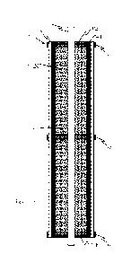
Figure la illustrates an embodiment of the present invention applied to a
vertical
length of pipe as viewed from the top of the pipe.
Figure lb illustrates a side cut-away view of the pipe and pipe insulation
system of
Figure la.
DETAILED DESCRIPTION OF THE INVENTION
Test methods refer to the most recent test method as of the priority date of
this
document when a date is not indicated with the test method number. References
to test
methods contain both a reference to the testing society and the test method
number. The
following test method abbreviations and identifiers apply herein: ASTM refers
to American
Society for Testing and Materials; EN refers to European Norm; DIN refers to
Deutsches
Institut fiir Normung; and ISO refers to International Organization for
Standards.
"Multiple" means two or more. "And/or" means "and, or as an alternative". All
ranges include endpoints unless otherwise indicated.
-3-
CA 02872638 2014-11-04
WO 2014/035501 PCT/US2013/042798
"Polymer", unless indicated otherwise, refers to both homopolymer and
copolymer.
Unless otherwise indicated, "copolymer" includes block copolymer, graft
copolymer,
alternating copolymer and random copolymer.
"Vertical" refers to alignment parallel to Earth's gravitational field at the
location of
the article being referenced. "Horizontal" refers to alignment perpendicular
to the Earth's
gravitational field at the location of the article being referenced.
"Vertically oriented" and
"non-horizontal" are synonymous and refer to an orientation having a vertical
component,
preferably entirely vertical. For example anything that is not perfectly
horizontal is
vertically oriented.
"Top" refers to the highest (most remote from the center of the Earth) portion
of a
vertically oriented article, generally the highest surface of that article.
"Bottom" refers to
the lowest, typically lowest surface, of an article where lowest refers to
closest to the center
of the Earth.
The present invention comprises sections of thermoplastic polymer foam.
Thermoplastic polymer foam comprises a thermoplastic polymer continuous phase
matrix
that defines multiple cells or void defined therein. The polymer foam can be
open-cell foam
or closed-cell foam. An open-cell foam has an open cell content of 30 percent
(%) or more,
and can have an open cell content of 50% or more, 60% or more, 70% or more 80%
or
more, 90% or more, 95% or more and can have 100% open cell content. Closed-
cell foam
has an open cell content of less than 30%, and can have an open cell content
of 20% or less,
10% or less, 5% or less and can have zero percent open cell content. Determine
percent
open cell content according to American Society for Testing and Materials
(ASTM) method
D6226-05. Desirably, the thermoplastic polymer foam is closed-cell foam in
order to be
more thermally insulating. The thermoplastic polymer foam desirably has a
density of 25
kilograms per cubic meter (kg/m3) or more, preferably 30 kg/m3 or more and
more
preferably 35 kg/m3 or more and at the same time desirably has a density of 80
kg/m3 or
lower and can have a density of 50 kg/m3 or less and even 40 kg/m3 or less.
Lower densities
are particularly desirable for thicker thermoplastic polymer foam in order to
minimize
polymer available for melting while maximizing insulation value. Determine
thermoplastic
polymer foam density according to ASTM D1622-08.
Suitable thermoplastic polymers that can form the continuous phase matrix of
the
thermoplastic polymer foam include any one or any combination of more than one
-4-
CA 02872638 2014-11-04
WO 2014/035501 PCT/US2013/042798
thermoplastic polymer. Olefinic polymers, alkenyl-aromatic homopolymers and
copolymers
comprising both olefinic and alkenyl aromatic components are suitable.
Examples of
suitable olefinic polymers include homopolymers and copolymers of ethylene and
propylene.
Desirably, the foam core is a polymeric foam core having a polymer matrix
comprising or consisting of one or more than one alkenyl-aromatic polymer. An
alkenyl-
aromatic polymer is a polymer containing alkenyl aromatic monomers polymerized
into the
polymer structure. Alkenyl-aromatic polymer can be homopolymers, copolymers or
blends
of homopolymers and copolymers. Alkenyl-aromatic copolymers can be random
copolymers, alternating copolymers, block copolymers or any combination
thereof and may
be linear, branched or a mixture thereof.
Styrenic polymers are particularly desirably alkenyl-aromatic polymers.
Styrenic
polymers have styrene monomer polymerized in the polymer backbone and include
styrene
homopolymer, copolymer and blends thereof.
Examples of styrenic copolymers suitable for the present invention include
copolymers of styrene with one or more of the following: acrylic acid,
methacrylic acid,
ethacrylic acid, maleic acid, itaconic acid, acrylonitrile, maleic anhydride,
methyl acrylate,
ethyl acrylate, isobutyl acrylate, n-butyl acrylate, methyl methacrylate,
vinyl acetate and
butadiene.
Styrene-acrylonitrile copolymer (SAN) is a particularly desirable alkenyl-
aromatic
polymer for use in the present invention because of its ease of manufacture
and monomer
availability. SAN copolymer can be a block copolymer or a random copolymer,
and can be
linear or branched. SAN has higher heat distortion temperature than
polystyrene
homopolymer, which provides for foam having a higher use temperature than
polystyrene
homopolymer foam. Desirable embodiments of the present process employ polymer
compositions that comprise, even consist of SAN. The one or more alkenyl-
aromatic
polymer, even the polymer composition itself may comprise or consist of a
polymer blend of
SAN with another polymer such as polystyrene homopolymer.
Whether the polymer composition contains only SAN, or SAN with other polymers,
the acrylonitrile (AN) component of the SAN is desirably present at a
concentration of one
weight-percent (wt%) or more, preferably five wt% or more, more preferably ten
wt% or
more based on the weight of all thermoplastic polymers in the thermoplastic
polymer
-5-
CA 02872638 2014-11-04
WO 2014/035501 PCT/US2013/042798
matrix. The AN component of the SAN is desirably present at a concentration of
fifty wt%
or less, typically thirty wt% or less based on the weight of all thermoplastic
polymers in the
thermoplastic polymer matrix.
The thermoplastic polymer foam can be any type of thermoplastic polymer foam
in
the broadest scope of the present invention including both extruded and
expanded foam,
however, extruded foam is most desirable. Expanded foam, such as expanded
polystyrene
(EPS) foam comprises multiple foam components, such as beads or strands, of
expandable
foam that are generally expanded within a constraint (for example, within a
mold or
between constraining plates) to force the expanding foam structures together
so that they
fuse to one another to form a composite foam structure. Expanded foams are
characterized
by having a skin of polymer extending throughout the polymer foam and
surrounding
groups of foam cells. These skins correspond to the surfaces of the expanding
foam
components that contacted and fused together during expansion and molding of
the resulting
foam composite. The skin of polymer has a greater density and/or thickness
than cell walls
on average or the resulting foam structure on average. Expanded bead foam and
strand
foam are two types of expanded polymer foams. Expanded bead foam comprises
multiple
foam beads that expand and fuse together to form a foam structure having
groupings of cells
enclosed in shells of polymer skin corresponding to surface of the individual
beads. Strand
foam comprises multiple strands of expanding polymer foam that contact one
another and
fuse together resulting in a foam structure having grouping of cells within
polymer skins
that generally extend in one dimension of the resulting foam.
In contrast to expanded polymer foam, extruded polymer foams such as extruded
polystyrene (XPS) foam are made by extruding and expanding a single expanding
mass of
polymer into polymer foam that is free of polymer skin networks having a
density or
thickness greater than the average cell wall or foam density that extend
throughout the
polymer foam and enclosing groups of cells. Extruded polymer foam expands from
a single
mass of polymer rather than result by fusing multiple expanding foam masses
together.
Each expanding mass has a relatively thick or high density skin around it.
Therefore,
expanded polymer foam has networks of this skin throughout the foam while
extruded
polymer foam only has such a skin around its outer surface.
Extruded polymer foam is more desirable for the thermoplastic polymer foam of
the
present invention. Extruded polymer foam tends to be a better thermal
insulator and more
-6-
CA 02872638 2014-11-04
WO 2014/035501 PCT/US2013/042798
moisture resistant than expanded polymer foam. The network of relatively high
density
polymer skin can result in thermal shorts throughout the polymer foam, which
are absent in
extruded foam. Moisture can also find its way through voids along fused skins
forming a
network throughout expanded foam and undesirably result in both a decrease in
thermal
insulation and other problems associated with moisture. Desirably, the
thermoplastic
polymer foam is closed-cell extruded polystyrene foam.
The thermoplastic polymer foam can comprise additives dispersed within the
polymer matrix of the thermoplastic polymer foam. Examples of suitable
additives include
any one or any combination of more than one of the following: flame retardant
components
(for example: brominated polymers, non-polymeric brominated compounds,
phosphorous
components, and chlorinated compounds), infrared attenuating agents (for
example:
graphite, carbon black, titanium dioxide, alumina boehmite, and metal flake),
processing
aids, colorants and pigments.
The sections of thermoplastic polymer foam fit circumferentially around the
length
of a pipe that the pipe insulation of the system of the present invention is
insulating, where
each section extends lengthwise along the pipe. Sections refer to lengths of
thermoplastic
polymer foam that extend lengthwise along the pipe. Fitting circumferentially
around a
length of pipe means wrapping around the pipe, preferably entirely around the
pipe, in a
plane perpendicular to the length dimension of the pipe while extending
lengthwise along
the length of pipe. Length corresponds to the largest dimension of an article
and, with
respect to a pipe, the direction though which something can flow within the
pipe. Sections
of thermoplastic polymer foam can comprise two or more pieces of thermoplastic
foam that
fit together to wrap circumferentially around a length of pipe.
The sections of thermoplastic polymer foam extend along the pipe for a
distance less
than the entire length of the pipe. The present pipe insulation system further
comprises
rings of melt barrier material that fit circumferentially around the length of
pipe and that are
located at the top and bottom ends of non-horizontal sections of the length of
pipe and
between sections of thermoplastic polymer foam along the length of pipe. The
spacing
between rings of melt barrier material are such that at least a portion of a
ring of melt barrier
material is present within any 250 centimeter distance, preferably within any
100 centimeter
distance, and more preferably within any 50 centimeter distance along the
length of the
length of pipe. The rings of melt barrier material abut any adjacent section
of thermoplastic
-7-
CA 02872638 2014-11-04
WO 2014/035501 PCT/US2013/042798
foam along the length of pipe. The rings of melt barrier material can either
be adhered to
adjacent sections of thermoplastic foam or be non-adhered and independent from
adjacent
section of thermoplastic foam.
The rings of melt barrier material desirably extend at least ten millimeters,
preferably
20 millimeters or more and can extend for 30 millimeters or more, 40
millimeter or more
even 50 millimeters or more and at the same time generally extends for 300
millimeters or
less, and can extend for 200 millimeter or less, 100 millimeter or less, 80
millimeters or
less, 50 millimeters or less and even 30 millimeter or less along the length
dimension of the
length of pipe.
The rings of melt barrier material serve at least the following functions in
the present
invention when a length of pipe insulated with the present invention is
exposed to fire: (1)
prevents free flow of molten thermoplastic polymer foam towards the bottom of
non-
horizontal lengths of pipe; (2) inhibits chimney effect during of flames
freely burning up
towards the top of non-horizontal lengths of pipe when exposed to fire; and
(3) in
combination with the support band the rings of melt barrier hold the pipe
insulation system
in place during a fire even when the thermoplastic polymer foam component
melts.
Therefore, the melt barrier material desirably remains intact when exposed to
a fire for a
longer period of time than the thermoplastic foam in the system. Preferably,
the melt barrier
material remains intact throughout the duration of exposure to a fire, at
least during the
testing method specified for EN13501-1 classifications. In that regard, the
melt barrier
material either decomposes instead of melting or has a melting temperature of
800 degrees
Celsius ( C) or higher, preferably 1000 or higher.
In the broadest scope of the present invention the melt barrier material can
be made
of, for example, any one or combination of materials selected from polymer,
metal or
mineral. At the same time, the melt barrier material can be solid, fibrous or
cellular. For
example, the melt barrier material can be foam (that is, a cellular structure
having a
continuous matrix of material that defines a plurality of cells therein) that
is made from
polymer, metal, mineral or any combination thereof. The melt barrier material
is desirably
foam in order to minimize the weight of the insulating system and increase the
thermal
resistance of the system. In particular, the melt barrier material is
desirably foam of a
material that is a thermal conductive material, such as a polymeric foam,
foamed glass,
foamed silicate or aerogel. For example, the melt barrier material is
desirably polymeric
-8-
CA 02872638 2014-11-04
WO 2014/035501 PCT/US2013/042798
foam such as a polyisocyanurate. Desirably, the melt barrier material is
polymeric foam,
such as polyisocyanurate foam, that has an open cell content of less than 30
percent as
determined by ASTM D6226-05 in order to optimize thermal insulating properties
through
the melt barrier material. Foamed glass is also a particularly melt barrier
material. In order
to keep the weight of the pipe insulation system to a minimum, it is desirable
for the melt
barrier material to have a density of 500 kilograms per cubic meter (kg/m3) or
less,
preferably 250 kg/m3 or less, more preferably 180 kg/m3 or less and can be 120
kg/m3 or
less, 100 kg/m3 or less, 80 kg/m3 or less and even 50 kg/m3 or less. At the
same time, is it
desirable for the melt barrier material to have a density of 30 kg/m3 or more,
more desirably
35 kg/m3 or more and can be 40 kg/m3 or more 80 kg/m3 or more, or even 100
kg/m3 or
more in order to optimize structural integrity when exposed to flames.
Determine foam
density according to ASTM D1622-08.
The thermoplastic polymer foam and the rings of melt barrier material can have
the
same thickness or have different thicknesses. "Thickness" refers to the
dimension
perpendicular the length and extending in a direction radially from the length
of pipe. The
thermoplastic polymer and the rings of melt barrier material can have the same
thickness.
However, the thermoplastic polymer and the rings of melt barrier material can
have different
thicknesses. Additionally, different rings of melt barrier material can have
different
thicknesses from one another. For example, the rings of melt barrier material,
or a selection
of rings of melt barrier material, can have a thickness greater than the
thermoplastic polymer
foam or thinner than the thermoplastic polymer foam.
The thermoplastic polymer foam and the rings of melt barrier material can
independently (meaning the thermoplastic polymer foam, the rings of melt
barrier material
or any selection of the thermoplastic polymer foam and one or more or all of
the rings of
melt barrier material) have a thickness of five millimeters or more, ten
millimeters or more
20 millimeters or more, 25 millimeters or more, 30 millimeters or more, 40
millimeters or
more, 50 millimeters or more, 60 millimeters or more, 70 millimeters or more
and even 75
millimeters or more. A the same time, the thickness of the thermoplastic
polymer foam and
the melt barrier material is generally 50 centimeters or less and can be 30
centimeters or
less, 10 centimeters or less, 80 millimeters or less, 75 millimeters or less,
even 50
millimeters or less. Increasing the thickness of the thermoplastic polymer
foam tends in to
decrease the thermal conduction through the foam. Increasing the thickness of
the melt
-9-
CA 02872638 2014-11-04
WO 2014/035501 PCT/US2013/042798
barrier material creates a greater barrier for molten thermoplastic polymer
foam from
draining downwards and flames from rising upwards along a length of pipe.
The pipe insulation system can be free of rubber-like material or fiber
reinforced
polyester and/or epoxy compounds between sections of thermoplastic polymer
foam. The
pipe insulation system can be completely free of rubber-like material or fiber
reinforced
polyester and/or epoxy compounds.
The pipe insulation system of the present invention further comprises a mesh
around
the sections of thermoplastic polymer foam and ring of melt barrier material
and extending
along the length of the pipe covered by the insulation system. The mesh can
be, for
example, a woven or non-woven type material. The mesh wraps around the
sections of
thermoplastic polymer foam and melt barrier material so that when the pipe
insulation
system is insulating a length of pipe the thermoplastic polymer foam and melt
barrier
material are between the mesh and the length of pipe. The mesh serves to
assist in holding
the thermoplastic polymer foam and melt barrier material in place when exposed
to heat and
fire.
The mesh comprises mesh members spaced apart to define spaces between mesh
members. The spaces between mesh members are important because if the spaces
are too
small then the mesh will trap heat against the thermoplastic polymer foam and
accelerate
melting of the thermoplastic polymer foam. If the spaces between mesh members
are too
large, then molten thermoplastic polymer foam will freely flow out through the
mesh. The
spaces between mesh members have an average size of ten square millimeters (sq
mm) or
more and can be 10 sq mm or more, 20 sq mm or more, 30 sq mm or more, 50 sq mm
or
more, 75 sq mm or more, 100 sq mm or more, even 150 sq mm or more. At the same
time,
the spaces between the mesh members have an average size of 200 sq mm or less
and can
have an average size of 175 sq mm or less, 150 sq mm or less, 125 sq mm or
less and even
100 sq mm or less.
The mesh members are made of material that either decomposes instead of
melting
or has a melting temperature of 800 C or higher, preferably 1000 C or higher.
Suitable
mesh member materials include, for example, glass, glass fiber, mineral fiber,
metal fiber,
and aramid fibers.
A metallic covering encloses the thermoplastic polymer foam, melt barrier
material
and mesh. The metallic covering is desirably made of aluminum. The thickness
(as
-10-
CA 02872638 2014-11-04
WO 2014/035501 PCT/US2013/042798
measured in a radial direction relative to a length of pipe around which the
pipe insulation
resides) is desirably 10 micrometers or more, preferably 20 micrometers or
more and can be
30 micrometer or more, 40 micrometers or more, 50 micrometers or more, 75
micrometers
or more, even 100 micrometers or more. At the same time, the thickness of the
metallic
covering is generally 1000 micrometers or less, and can be 500 micrometers or
less, even
100 micrometers or less.
The metallic covering can, for example, be in the form of a tube or a sheet
that wraps
around the mesh and thermoplastic polymer foam. When the metallic covering is
in the
form of a sheet that wraps around the mesh and thermoplastic polymer foam, it
is desirable
for the metallic covering to overlap itself, mechanically interlock with
itself or both overlap
and mechanically interlock with itself so as to ensure it remains in place
even if the
thermoplastic polymer foam inside of it melts away. If the metallic covering
overlaps itself
it desirably overlaps as much as 25% of the circumference or more, preferably
50% of the
circumference or more around the mesh and thermoplastic polymer foam. It is
further
desirable for the overlapping metallic covering to be adhered to itself either
using an
adhesive or by mechanically interlocking with itself or with both an adhesive
and by
mechanically interlocking. Lengths of metallic covering that extend less than
the full length
of the pipe insulation system also desirably overlap, mechanically interlock
with or both
overlap and mechanically interlock with adjacent lengths of metallic covering.
Overlapping
lengths of metallic covering are desirably adhered to one another,
mechanically interlocked
with one another or both adhered to one another and mechanically interlocked
with one
another. Suitable adhesives for adhering the metallic covering to itself
include epoxy
adhesives, acrylic adhesives and polyurethane adhesives.
Optionally, an epoxy adhesive and even a layer of epoxy coating reside between
the
mesh and the sections of thermoplastic polymer foam. Alternatively, or
additionally, an
epoxy adhesive or even a layer of epoxy coating can reside between the
metallic covering
and the mesh. Epoxy adhesives and coatings can be useful to adhere components
of the
present pipe insulation together.
Optionally, a metallic covering as described can also reside around the
thermoplastic
polymer foam between the mesh member and the thermoplastic polymer foam. Such
a
configuration sandwiches the mesh member between two metallic covering layers.
While
both metallic covering layers are as described herein, the two metallic
covering layers can be
-11-
CA 02872638 2014-11-04
WO 2014/035501 PCT/US2013/042798
different or the same with respect to one another. That is, the metallic
covering layers can,
for example, differ in metal composition, thickness, or both metal composition
and
thickness. It is desirable for the metallic covering between the mesh and the
polymeric
foam to be as thick or, more desirably, thicker than the metallic covering
enclosing the
thermoplastic polymer foam, melt barrier material and mesh.
Support bands around the pipe insulation system of the present invention hold
the
pipe insulation system to a pipe around which the pipe insulation system
resides. Support
bands fit circumferentially around the metallic covering of the pipe
insulation system and
squeeze or compress the pipe insulation system against a length of pipe around
which the
pipe insulation system resides. Desirably, position the support bands so that
they extend
around the pipe insulation system with a ring of melt barrier material between
the support
band and the length of pipe around which the pipe insulation system resides.
In such an
orientation the ring of melt barrier material serves as a firm and stable
component of the
pipe insulation system even if exposed to heat or fire, allowing the support
band to keep the
pipe insulation system in place even if the thermoplastic polymer foam
sections melt.
Support bands are desirably metal but can be made of any material that has a
melting
temperature of 800 degrees Celsius or higher or that decomposes instead of
melting.
Examples of suitable support band materials include steel, aluminum and glass-
reinforced
plastic banding. It is desirable to provide a support band around the rest of
the pipe
insulation system at each ring of melt barrier material so that at each ring
of melt barrier
material there is a support band squeezing the pipe insulation system against
a pipe around
which the pipe insulation system resides.
Figures la and lb illustrate (not to scale) an embodiment of the present
invention as
applied onto a length of pipe. Figure la illustrates an end-on view looking
down at the top
of the invention applied to a vertical pipe. Figure lb illustrates a cut-away
side view along
viewing lines A shown in Figure la.
Figures la and lb illustrate Example 1 in the form of pipe insulation system
10 is
around 22 millimeter diameter pipe 1. Pipe insulation system 10 comprises
sections of
extruded polystyrene foam 20 (only visible in Figure lb because ring of melt
barrier
material 30a precludes viewing in Figure la) that extend 950 millimeters
lengthwise along
pipe 1. Extruded polystyrene foam 20 has a density of about 35 kg/m3, an open
cell content
of less than 5% (for example STYROFOAMTm FB-X brand extruded polystyrene foam,
-12-
CA 02872638 2014-11-04
WO 2014/035501 PCT/US2013/042798
STYROFOAM is a trademark of The Dow Chemical Company). Ring of melt barrier
material 30a resides at the top of pipe insulation system 10. Ring of melt
barrier material
30b resides at the bottom of pipe insulation system 10. Rings of melt barrier
material 30
reside at spacings of 950 millimeters along the distance of the length of pipe
1. The rings of
melt barrier material 30a, 30b, and 30 are each 50 millimeters tall (that is,
they extend 50
millimeters along the length dimension of pipe 1). The rings of melt barrier
material are all
closed-cell polyisocyanurate foam having a density of about 35 kg/m3 (For
example,
TARECPIRTm brand insulation, TARECPIR is a trademark of Kinspand Tarec). Mesh
40
extends the length of the pipe insulation system and wraps around sections of
polystyrene
foam 20 and rings of melt barrier material 30a, 30b, and 30. Mesh 40 is glass
fibers having
a spacing between fibers of 25 square millimeters. An epoxy adhesive (not
shown) resides
between Mesh 40 and extruded polystyrene foam 20. Aluminum foil 50 wraps
around the
rest of pipe insulation system 10 and extends lengthwise along length of pipe
1. Aluminum
foil 50 has a thickness of 40-75 micrometers (ideally, approximately 70
micrometers) as
measured in a direction radially relative to length of pipe 1. Support bands
60 extend
around the rest of the pipe insulation system and are located around rings of
melt barrier
material 30.
Based on testing of similar systems, pipe insulation system 10 is expected to
achieve
a Class DL rating or better according to EN13501-1 classification ratings.
An additional example, Example 2, of a pipe insulation system of the present
invention is similar to that illustrated in Figures la and lb, but with the
following changes:
(a) there is a second metal barrier material (aluminum foil that is 30-50
micrometers thick, preferably about 50 micrometers) between the mesh material
40 and the thermoplastic polymer foam 20 so that mesh 40 is sandwiched
between the second metal barrier material and metal barrier material 50;
(b) Aluminum foil 50 (which is a metal barrier material) is 30-50 micrometers
(ideally, approximaetely 50 micrometers) thick;
(c) Rings of melt barrier material 30a, 30b and 30 are foamed glass having a
density
of 120 kg/m3; and
-13-
CA 02872638 2014-11-04
WO 2014/035501 PCT/US2013/042798
(d) The thickness of thermoplastic polymer foam 20 and rings of melt barrier
material 30, 30a and 30b are all at the same time either 25-30 millimeters, 40
millimeters, or 50 millimeters.
Under EN 13501-1, this additional example using a thickness of 25-30
millimeters
achieves a CL classification and is expected to achieve a classification of BL
by using a
thermoplastic polymer foam having a density of 33 kg/m3 or less. When the
thickness of the
thermoplastic polymer foam and rings of melt barrier material are all 40
millimeters or 50
millimeters this additional example achieves a DL classification and is
expected to achieve a
CL classification using a thermoplastic polymer foam having a density of 33
kg/m3 or less.
As a point of reference, Comparative Example A is similar to Example 2 except
the
extruded polystyrene foam is 35 kg/m3 density STYROFOAM TM FB-X brand extruded
polystyrene foam and has a thickness of 40 millimeters. There are no melt
barrier rings in
the pipe insulation system of Comparative Example A, only the extruded
polystyrene foam
in the aluminum foil/mesh/aluminum foil vapor barrier wrap. The burn
properties of
Comparative Example A are as follows: FIGRA 0.4 MJ of 285.20 Watts per second,
THR600 of 28.80 Mega Joules, SMOGRA of 156.60 square meters per second per
second,
and SPR600 of 1970 square meters. As a result, Example 3 achieves a SBI
Classification
under EN13501-1 of DL s3 dO.
Example 3 is similar to Example 2, but with the following changes: Pipe
insulation
system 10 is 1500 millimeters (mm) long. The extruded polystyrene foam
(STYROFOAM
IBTRBEX brand extruded polystyrene foam) has a density of 33 kg/m3 and a
thickness of 50
mm. Each ring of melt barrier material (30, 30a and 30b) are 100 mm tall and
50 mm thick.
Height is measured along pipe 1. Thickness is measured in the radial dimension
of the pipe.
The melt barrier material is 120 kg/m3 density foamed glass (FOAMGLASTm T4,
FOAMGLAS is a trademark of Pittsburgh corning Corporation). The spacing
between the
rings of melt barrier material is 450 mm as measured between the center of
rings of melt
barrier material. When subject to EN13823 burn property testing Example 3 has
the
following characteristics: FIGRA 0.4 MJ of 103.30 Watts per second, THR600 of
11.90
Mega Joules, SMOGRA of 68.0 square meters per second per second, and SPR600 of
668.4
-14-
CA 02872638 2014-11-04
WO 2014/035501
PCT/US2013/042798
square meters. As a result, Example 3 achieves a SBI Classification under
EN13501-1 of
CL s2 dO.
Example 3, as compared with Comparative Example A, reveals the tremendous
improvement in EN13501-1 classification due to the presence of the melt
barrier material
rings in the pipe insulation system of the present invention.
-15-