Sélection de la langue

Search

Sommaire du brevet 2873491 

Énoncé de désistement de responsabilité concernant l'information provenant de tiers

Une partie des informations de ce site Web a été fournie par des sources externes. Le gouvernement du Canada n'assume aucune responsabilité concernant la précision, l'actualité ou la fiabilité des informations fournies par les sources externes. Les utilisateurs qui désirent employer cette information devraient consulter directement la source des informations. Le contenu fourni par les sources externes n'est pas assujetti aux exigences sur les langues officielles, la protection des renseignements personnels et l'accessibilité.

Disponibilité de l'Abrégé et des Revendications

L'apparition de différences dans le texte et l'image des Revendications et de l'Abrégé dépend du moment auquel le document est publié. Les textes des Revendications et de l'Abrégé sont affichés :

  • lorsque la demande peut être examinée par le public;
  • lorsque le brevet est émis (délivrance).
(12) Demande de brevet: (11) CA 2873491
(54) Titre français: ENSEMBLE DE BUREAU PORTATIF
(54) Titre anglais: PORTABLE DESK ASSEMBLY
Statut: Réputée abandonnée et au-delà du délai pour le rétablissement - en attente de la réponse à l’avis de communication rejetée
Données bibliographiques
(51) Classification internationale des brevets (CIB):
  • A47B 3/02 (2006.01)
  • A47B 3/10 (2006.01)
  • A47B 9/16 (2006.01)
(72) Inventeurs :
  • ARISHENKOFF, MICHELE (Canada)
  • HICKS, GEOFFREY (Canada)
  • SICKLING, JOHN (Canada)
(73) Titulaires :
  • MICHELE ARISHENKOFF
  • GEOFFREY HICKS
  • JOHN SICKLING
(71) Demandeurs :
  • MICHELE ARISHENKOFF (Canada)
  • GEOFFREY HICKS (Canada)
  • JOHN SICKLING (Canada)
(74) Agent: GOWLING WLG (CANADA) LLP
(74) Co-agent:
(45) Délivré:
(22) Date de dépôt: 2014-12-03
(41) Mise à la disponibilité du public: 2015-12-13
Licence disponible: S.O.
Cédé au domaine public: S.O.
(25) Langue des documents déposés: Anglais

Traité de coopération en matière de brevets (PCT): Non

(30) Données de priorité de la demande:
Numéro de la demande Pays / territoire Date
14/303,732 (Etats-Unis d'Amérique) 2014-06-13

Abrégés

Abrégé anglais


A portable desk assembly for providing a work surface having an adjustable
height includes a pair of stands each movably coupled together. The pair of
stands is
positionable between a deployed position and a stored position. A panel is
coupled to the
pair of stands. The panel may provide a work surface. A lock is coupled
between the
pair of stands. The lock retains the panel at a selected height when the pair
of stands is
positioned in the deployed position.

Revendications

Note : Les revendications sont présentées dans la langue officielle dans laquelle elles ont été soumises.


WHAT IS CLAIMED IS:
1. A portable desk assembly configured to provide a work surface
having an
adjustable height, said assembly comprising:
a pair of stands each movably coupled together, said pair of stands being
positionable between a deployed position and a stored position;
a panel coupled to said pair of stands wherein said panel is configured to
provide
the work surface; and
a lock coupled between said pair of stands, said lock retaining said panel at
a
selected height when said pair of stands is positioned in said deployed
position.
2. The assembly according to claim 1, wherein said pair of stands each
comprising a pair of longitudinal arms, each of said pair of longitudinal arms
of said pair
of stands having a first end and a second end, said first end of each of said
pair of
longitudinal arms of said pair of stands being coupled to a lateral arm of
each of said pair
of stands such that each of said pair of stands each has a U-shape.
3. The assembly according to claim 2, further comprising each of a first
one
of said pair of longitudinal arms of said pair of stands being rotatably
coupled together,
each of a second one of said pair of longitudinal arms of said pair of stands
being
rotatably coupled together.
4. The assembly according to claim 3, further comprising said pair of
stands
forming an X-shape when said pair of stands are positioned in said deployed
position
having said lateral arm of each of said pair of stands abutting a support
surface, said
second end of each of said pair of longitudinal arms of said pair of stands
being directed
upwardly from the support surface.
6

5. The assembly according to claim 3, wherein each of said first
longitudinal
arms of said pair of stands being coextensive with one another and each of
said second
longitudinal arms of said pair of stands being coextensive with one another
when said
pair of stands is positioned in said stored position.
6. The assembly according to claim 1, wherein said panel having a primary
end and a secondary end, said panel having an exterior edge of said panel
extending
between a top surface and a bottom surface of said panel, each of a first
lateral side and a
second lateral side of said exterior edge of said panel being directed
downwardly from
said top surface of said panel such that a pair of lips is defined on said
panel.
7. The assembly according to claim 6, further comprising a second end of
each of a pair of longitudinal arms of a first one of said pair of stands
being movably
coupled to an inner surface of an associated one of said pair of lips on said
panel, said
second end of said pair of longitudinal arms of said first leg each being
positioned
proximate said primary end of said panel.
8. The assembly according to claim 7, further comprising said panel
extending between said second end of each of said pair of longitudinal arms of
each of
said pair of stands when said pair of stands is positioned in said deployed
position such
that said panel is supported above the support surface.
9. The assembly according to claim 2, wherein a primary arm coupled to and
extending between said pair of longitudinal arms of a first one of said pair
of stands, said
primary arm being positioned proximate said second end of each of said pair of
longitudinal arms of said first stands.
7

10. The assembly according to claim 2, wherein said lock having a basic end
and an alternative end, each of said basic and alternative ends of said lock
being rotatably
coupled to an associated one of said pair of longitudinal arms of a second one
of said pair
of stands, said lock being positioned proximate said second end of each of
said pair of
longitudinal arms of said second leg.
11. The assembly according to claim 1, further comprising a slide arm
having
a fixed end and a sliding end, said fixed end of said slide arm being hingedly
coupled to a
lower side of a primary arm, said fixed end of said slide arm being centrally
positioned on
said primary arm.
12. The assembly according to claim 11, further comprising said sliding end
of
said slide arm extending through a front edge and a back edge of said lock
such that said
slide arm is slidably coupled to said lock, said lock engaging said slide arm
such that a
second end of each of a pair of longitudinal arms of each of said pair of
stands are
retained a selected distance apart when said pair of stands is positioned in
said deployed
position.
13. The assembly according to claim 12, further comprising said panel being
supported a selected distance above the support surface when said lock engages
said slide
arm.
14. A portable desk assembly configured to provide a work surface having an
adjustable height, said assembly comprising:
a pair of stands each comprising a pair of longitudinal arms, each of said
pair of
longitudinal arms of said pair of stands having a first end and a second
end, said first end of each of said pair of longitudinal arms of said pair of
stands being coupled to a lateral arm of each of said pair of stands such
that each of said pair of stands each has a U-shape.,
8

each of a first one of said pair of longitudinal arms of said pair of stands
being
rotatably coupled together, each of a second one of said pair of
longitudinal arms of said pair of stands being rotatably coupled together,
said pair of stands forming an X-shape when said pair of stands are
positioned in a deployed position having said lateral arm of each of said
pair of stands abutting a support surface, said second end of each of said
pair of longitudinal arms of said pair of stands being directed upwardly
from the support surface;
each of said first longitudinal arms of said pair of stands being coextensive
with
one another and each of said second longitudinal arms of said pair of
stands being coextensive with one another when said pair of stands is
positioned in a stored position;
a panel having a primary end and a secondary end, said panel having an
exterior
edge of said panel extending between a top surface and a bottom surface of
said panel, each of a first lateral side and a second lateral side of said
exterior edge of said panel being directed downwardly from said top
surface of said panel such that a pair of lips is defined on said panel;
said second end of each of said pair of longitudinal arms of a first one of
said pair
of stands being movably coupled to an inner surface of an associated one
of said pair of lips on said panel, said second end of said pair of
longitudinal arms of said first stand each being positioned proximate said
primary end of said panel;
said panel extending between said second end of each of said pair of
longitudinal
arms of each of said pair of stands when said pair of stands is positioned in
said deployed position such that said panel is supported above the support
surface wherein said panel is configured to provide the work surface;
a primary arm coupled to and extending between said pair of longitudinal arms
of
said first stand, said primary arm being positioned proximate said second
end of each of said pair of longitudinal arms of said first stand;
9

a lock having a basic end and an alternative end, each of said basic and
alternative
ends of said lock being rotatably coupled to an associated one of said pair
of longitudinal arms of a second one of said pair of stands, said lock being
positioned proximate said second end of each of said pair of longitudinal
arms of said second stand;
a slide arm having a fixed end and a sliding end, said fixed end of said slide
arm
being hingedly coupled to a lower side of said primary arm, said fixed end
of said slide arm being centrally positioned on said primary arm; and
said sliding end of said slide arm extending through a front edge and a back
edge
of said lock such that said slide arm is slidably coupled to said lock, said
lock engaging said slide arm such that said second end of each of said pair
of longitudinal arms of each of said pair of stands are retained a selected
distance apart when said pair of stands is positioned in said deployed
position, said panel being supported a selected distance above the support
surface when said lock engages said slide arm.

Description

Note : Les descriptions sont présentées dans la langue officielle dans laquelle elles ont été soumises.

CA 02873491 2014-12-03
,
,
PORTABLE DESK ASSEMBLY
TECHNICAL FIELD
The disclosure relates to desk devices and more particularly pertains to a new
desk
device for providing a work surface having an adjustable height.
SUMMARY
An embodiment of the disclosure meets the needs presented above by generally
comprising a pair of stands each movably coupled together. The pair of stands
is
positionable between a deployed position and a stored position. A panel is
coupled to the
pair of stands. The panel may provide a work surface. A lock is coupled
between the
pair of stands. The lock retains the panel at a selected height when the pair
of stands is
positioned in the deployed position.
There has thus been outlined, rather broadly, the more important features of
the
disclosure in order that the detailed description thereof that follows may be
better
understood, and in order that the present contribution to the art may be
better appreciated.
There are additional features of the disclosure that will be described
hereinafter and
which will form the subject matter of the claims appended hereto.
The objects of the disclosure, along with the various features of novelty
which
characterize the disclosure, are pointed out with particularity in the claims
annexed to and
forming a part of this disclosure.
BRIEF DESCRIPTION OF THE DRAWINGS
The disclosure will be better understood and objects other than those set
forth
above will become apparent when consideration is given to the following
detailed
description thereof. Such description makes reference to the annexed drawings
wherein:
1

CA 02873491 2014-12-03
,
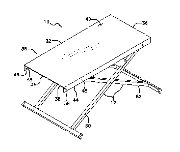
Figure 1 is a top perspective view of a portable desk assembly according to an
embodiment of the disclosure.
Figure 2 is a front perspective view of an embodiment of the disclosure.
Figure 3 is a front view of an embodiment of the disclosure.
Figure 4 is a perspective view of an embodiment of the disclosure in a stored
position.
Figure 5 is a bottom view of an embodiment of the disclosure.
DETAILED DESCRIPTION
With reference now to the drawings, and in particular to Figures 1 through 5
thereof, a new desk device embodying the principles and concepts of an
embodiment of
the disclosure and generally designated by the reference numeral 10 will be
described.
As best illustrated in Figures 1 through 5, the portable desk assembly 10
generally
comprises a pair of stands 12. The pair of stands 12 each includes a pair of
longitudinal
arms 14. Each of the pair of longitudinal arms 14 of the pair of stands 12 has
a first end
16 and a second end 18. The first end 16 of each of the pair of longitudinal
arms 14 of
the pair of stands 12 is coupled to a lateral arm 20 of each of the pair of
stands 12. Each
of the pair of stands 12 each has a U-shape. The lateral arm 20 of each of the
pair of
stands 12 has a front end 22 and a back end 24. Each of the pair of
longitudinal arms 14
of each of the pair of stands 12 is spaced inwardly from an associated one of
the front 22
and back 24 ends of the associated one of each of the lateral arms 20 of the
pair of stands
12.
2

CA 02873491 2014-12-03
Each of a first one 26 of the pair of longitudinal arms 14 of the pair of
stands 12 is
rotatably coupled together. Additionally, each of a second one 28 of the pair
of
longitudinal arms 14 of the pair of stands 12 is rotatably coupled together.
The pair of
stands 12 forms an X-shape when the pair of stands 12 are positioned in a
deployed
position. Moreover, the lateral arm 20 of each of the pair of stands 12 abuts
a support
surface 30. The second end 18 of each of the pair of longitudinal arms 14 of
the pair of
stands 12 is directed upwardly from the support surface 30. Each of the first
longitudinal
arms 26 of the pair of stands 12 is coextensive with one another and each of
the second
longitudinal arms 28 of the pair of stands 12 is coextensive with one another
when the
pair of stands 12 is positioned in a stored position.
A panel 32 is provided. The panel 32 has a primary end 34 and a secondary end
36. The panel 32 has an exterior edge 38 of the panel 32 extending between a
top surface
40 and a bottom surface 42 of the panel 32. Each of a first lateral side 44
and a second
lateral side 46 of the exterior edge 38 of the panel 32 is directed downwardly
from the top
surface 40 of the panel 32. A pair of lips 48 is defined on the panel 32.
The second end 18 of each of the pair of longitudinal arms 14 of a first one
50 of
the pair of stands 12 is movably coupled to an inner surface 52 of an
associated one of the
pair of lips 48 on the panel 32. The second end 18 of the pair of longitudinal
arms 14 of
the first stand 50 is each positioned proximate the primary end 34 of the
panel 32. The
panel 32 lies flat on the pair of longitudinal arms 14 of each of the pair of
stands 12 when
the pair of stands 12 is positioned in the stored position. The panel 32
extends between
the second end 18 of each of the pair of longitudinal arms 14 of each of the
pair of stands
12 when the pair of stands 12 is positioned in the deployed position. The
panel 32 is
supported above the support surface 30 so the panel 32 may provide a work
surface.
3

CA 02873491 2014-12-03
,
A primary arm 54 is provided. The primary arm 54 is coupled to and extends
between the
pair of longitudinal arms 14 of the first stand 50. The primary arm 54 is
positioned
proximate the second end 18 of each of the pair of longitudinal arms 14 of the
first stand
50.
A lock 56 is provided. The lock 56 has a basic end 58 and an alternative end
60.
Each of the basic 58 and alternative 60 ends of the lock 56 is rotatably
coupled to an
associated one of the pair of longitudinal arms 14 of a second one 62 of the
pair of stands
12. The lock 56 is positioned proximate the second end 18 of each of the pair
of
longitudinal arms 14 of the second stand 62. A back edge 64 of the lock 56
extends
rearwardly from a front edge 66 of the lock 56. Moreover, the lock 56 has an A-
shape.
A slide arm 68 has a fixed end 70 and a sliding end 72. The fixed end 70 of
the
slide arm 68 is hingedly coupled to a lower side 74 of the primary arm 54. The
fixed end
70 of the slide arm 68 is centrally positioned on the primary arm 54. The
fixed end 70 of
the slide arm 68 may have a width that is greater than a width of the sliding
end 72 of the
slide arm 68.
The sliding end 72 of the slide arm 68 extends through each of the front 66
and
back 64 edges of the lock 56. The slide arm 68 is slidably coupled to the lock
56. The
lock 56 engages the slide arm 68. The second end 18 of each of the pair of
longitudinal
arms 14 of each of the pair of stands 12 are retained a selected distance
apart when the
pair of stands 12 is positioned in the deployed position. The panel 32 is
supported a
selected distance above the support surface 30 when the lock 56 engages the
slide arm 68.
A release 76 is movably coupled to the lock 56. The release 76 may be engaged
by a user 78. The slide arm 68 is freely movable in the lock 56 while the
release 76 is
engaged by the user 78. The lock 56 engages the slide arm 68 when the release
76 is not
engaged by the user 78 so the slide arm 68 is retained at a selected position
in the lock 56.
4

CA 02873491 2014-12-03
A stop 80 is coupled to the sliding end 72 of the slide arm 68. The stop 80
abuts
the back edge 64 of the lock 56 when the pair of stands 12 are positioned in
the stored
position. The stop 80 prevents the slide arm 68 from sliding out of the lock
56.
In use, the panel 32 is positioned in an extended position so the panel 32
extends
upwardly from the first stand 50. The release 76 is engaged and the first 50
and second
62 stands are positioned in the deployed position. The first 50 and second 62
stands are
positioned so the second ends 18 of each of the pair of longitudinal arms 14
of the pair of
stands 12 are positioned at a selected distance above the support surface 30.
The panel 32
is positioned in a lateral position so the bottom surface 42 of the panel 32
abuts the
second end 18 of each of the pair of longitudinal arms 14 of the second stand
62. The
pair of stands 12 are positioned in the stored position when the assembly 10
is not in use.
With respect to the above description then, it is to be realized that the
optimum
dimensional relationships for the parts of an embodiment enabled by the
disclosure, to
include variations in size, materials, shape, form, function and manner of
operation,
assembly and use, are deemed readily apparent and obvious to one skilled in
the art, and
all equivalent relationships to those illustrated in the drawings and
described in the
specification are intended to be encompassed by an embodiment of the
disclosure.
Therefore, the foregoing is considered as illustrative only of the principles
of the
disclosure. Further, since numerous modifications and changes will readily
occur to
those skilled in the art, it is not desired to limit the disclosure to the
exact construction
and operation shown and described, and accordingly, all suitable modifications
and
equivalents may be resorted to, falling within the scope of the disclosure.

Dessin représentatif
Une figure unique qui représente un dessin illustrant l'invention.
États administratifs

2024-08-01 : Dans le cadre de la transition vers les Brevets de nouvelle génération (BNG), la base de données sur les brevets canadiens (BDBC) contient désormais un Historique d'événement plus détaillé, qui reproduit le Journal des événements de notre nouvelle solution interne.

Veuillez noter que les événements débutant par « Inactive : » se réfèrent à des événements qui ne sont plus utilisés dans notre nouvelle solution interne.

Pour une meilleure compréhension de l'état de la demande ou brevet qui figure sur cette page, la rubrique Mise en garde , et les descriptions de Brevet , Historique d'événement , Taxes périodiques et Historique des paiements devraient être consultées.

Historique d'événement

Description Date
Demande non rétablie avant l'échéance 2019-12-03
Le délai pour l'annulation est expiré 2019-12-03
Lettre envoyée 2019-12-03
Représentant commun nommé 2019-10-30
Réputée abandonnée - omission de répondre à un avis sur les taxes pour le maintien en état 2018-12-03
Requête pour le changement d'adresse ou de mode de correspondance reçue 2018-01-16
Inactive : Page couverture publiée 2016-01-06
Demande publiée (accessible au public) 2015-12-13
Inactive : CIB en 1re position 2015-01-30
Inactive : CIB attribuée 2015-01-30
Demande reçue - nationale ordinaire 2014-12-09
Inactive : Certificat dépôt - Aucune RE (bilingue) 2014-12-09
Inactive : CQ images - Numérisation 2014-12-03
Inactive : Pré-classement 2014-12-03

Historique d'abandonnement

Date d'abandonnement Raison Date de rétablissement
2018-12-03

Taxes périodiques

Le dernier paiement a été reçu le 2017-11-22

Avis : Si le paiement en totalité n'a pas été reçu au plus tard à la date indiquée, une taxe supplémentaire peut être imposée, soit une des taxes suivantes :

  • taxe de rétablissement ;
  • taxe pour paiement en souffrance ; ou
  • taxe additionnelle pour le renversement d'une péremption réputée.

Les taxes sur les brevets sont ajustées au 1er janvier de chaque année. Les montants ci-dessus sont les montants actuels s'ils sont reçus au plus tard le 31 décembre de l'année en cours.
Veuillez vous référer à la page web des taxes sur les brevets de l'OPIC pour voir tous les montants actuels des taxes.

Historique des taxes

Type de taxes Anniversaire Échéance Date payée
Taxe pour le dépôt - générale 2014-12-03
TM (demande, 2e anniv.) - générale 02 2016-12-05 2016-11-21
TM (demande, 3e anniv.) - générale 03 2017-12-04 2017-11-22
Titulaires au dossier

Les titulaires actuels et antérieures au dossier sont affichés en ordre alphabétique.

Titulaires actuels au dossier
MICHELE ARISHENKOFF
GEOFFREY HICKS
JOHN SICKLING
Titulaires antérieures au dossier
S.O.
Les propriétaires antérieurs qui ne figurent pas dans la liste des « Propriétaires au dossier » apparaîtront dans d'autres documents au dossier.
Documents

Pour visionner les fichiers sélectionnés, entrer le code reCAPTCHA :


Pour visualiser une image, cliquer sur un lien dans la colonne description du document (Temporairement non-disponible). Pour télécharger l'image (les images), cliquer l'une ou plusieurs cases à cocher dans la première colonne et ensuite cliquer sur le bouton "Télécharger sélection en format PDF (archive Zip)" ou le bouton "Télécharger sélection (en un fichier PDF fusionné)".

Liste des documents de brevet publiés et non publiés sur la BDBC .

Si vous avez des difficultés à accéder au contenu, veuillez communiquer avec le Centre de services à la clientèle au 1-866-997-1936, ou envoyer un courriel au Centre de service à la clientèle de l'OPIC.

({010=Tous les documents, 020=Au moment du dépôt, 030=Au moment de la mise à la disponibilité du public, 040=À la délivrance, 050=Examen, 060=Correspondance reçue, 070=Divers, 080=Correspondance envoyée, 090=Paiement})


Description du
Document 
Date
(aaaa-mm-jj) 
Nombre de pages   Taille de l'image (Ko) 
Description 2014-12-02 5 209
Revendications 2014-12-02 5 196
Abrégé 2014-12-02 1 12
Dessins 2014-12-02 5 87
Dessin représentatif 2015-11-16 1 9
Certificat de dépôt 2014-12-08 1 177
Rappel de taxe de maintien due 2016-08-03 1 112
Courtoisie - Lettre d'abandon (taxe de maintien en état) 2019-01-13 1 174
Rappel - requête d'examen 2019-08-06 1 117
Avis du commissaire - Requête d'examen non faite 2019-12-23 1 537
Avis du commissaire - non-paiement de la taxe de maintien en état pour une demande de brevet 2020-01-13 1 534
Taxes 2016-11-20 1 25