Note : Les descriptions sont présentées dans la langue officielle dans laquelle elles ont été soumises.
CA 02873849 2014-11-17
WO 2013/170340
PCT/CA2012/050322
RECEIVER COIL ASSEMBLY WITH AIR AND FERROMAGNETIC CORED
SENSORS FOR GEOPHYSICAL SURVEYING
BACKGROUND
[0001] Embodiments of the described invention relate to the field of
airborne geological mapping and receiver systems used for such mapping.
[0002] Active source electromagnetic surveying such as time domain
electromagnetic (TDEM) surveying is a rapidly developing area of geophysical
surveying. It encompasses ground based and airborne applications. TDEM
geological mapping involves measuring the magnetic response of the earth to a
primary magnetic field transmitted by the survey system. The relation between
the transmitted field and the response is used to calculate the electrical
resistivity structure of the earth, from which geological information is
inferred.
[0003] An example of a TDEM surveying system and method is shown in
U.S. Patent No. 7,157,914.
[0004] Natural source electromagnetic surveying has traditionally been
performed using ground based techniques such as the magnetotelluric (MT)
technique. Recently, airborne surveying using natural source electromagnetic
techniques has become practical. In these techniques, two or more components
of naturally occurring random fluctuations of the electromagnetic field of the
earth are measured (possibly at different locations), and the frequency
dependent transfer functions between the measured components are calculated.
As in active source methods, the transfer functions are interpreted in terms
of
the electrical resistivity structure of the earth, from which geological
information
is inferred.
[0005] An example of a natural source electromagnetic surveying system
is
shown in U.S. Patent No. 6,876,202
[0006] An active source electromagnetic survey system has a
transmitter
and a receiver, while a natural source system has only a receiver. Typically a
transmitter includes a coil of one or more turns of electrical wire. When an
electric current is passed through the wire, a magnetic field is transmitted.
In
TDEM surveying, a pulsed current of alternating polarity is used, and the
1
CA 02873849 2014-11-17
WO 2013/170340
PCT/CA2012/050322
response of the earth is sensed in the "off" time between transmitter current
pulses.
[0007] A receiver or sensor typically includes of one or more
multiturn coils
of electrical wire. In the presence of a changing magnetic field, an
electrical
voltage appears across the terminals of each coil. This voltage can be
amplified
and recorded. Coils may have different orientations, making them sensitive to
variations in magnetic field components having different directions. Other
things
being equal, the sensitivity and noise floor of a receiver coil improve as the
coil
is scaled up in size. The signals used in natural source systems are typically
weaker, requiring larger receiver coils, compared to active source systems.
[0008] The response to movement and vibration of receivers used in
active
and natural source surveying systems is a significant noise source, especially
in
a turbulent airborne environment, becoming increasingly important as the
signal
frequency decreases below 100 Hz. A major contribution to this type of noise
is
caused by the motion of the receiver coil(s) relative to the static
geomagnetic
field. Motion or vibration that changes the total geomagnetic flux passing
through a receiver coil causes a electrical voltage to appear across the
terminals
of the coil. In the case of a rigid receiver coil, this can be caused by
rotation of
the coil. No receiver coil is perfectly rigid, so flexing of the coil also
contributes
to such voltages. These voltages are a type of noise that interferes with the
desired signal. Techniques for reduction of noise are important.
[0009] In some electromagnetic survey systems, the receiver is
sensitive
to changes in one component of the magnetic field, typically a nominally
vertical
component. Receivers that independently measure changes in two or three
substantially orthogonal components of the magnetic field provide improved
geological information, but are bulkier than single axis receivers.
[0010] Improved receiver systems for airborne geophysical survey
systems
are desirable.
SUMMARY
[0011] According to one example embodiment there is provided a receiver
coil assembly for performing geophysical surveys. The receiver coil assembly
includes a hollow outer shell defining a continuous internal passage that
forms a
loop; a multiturn receiver air coil extending around the continuous internal
2
CA 02873849 2014-11-17
WO 2013/170340
PCT/CA2012/050322
passage; and a first cored coil comprising multiturn solenoid windings about a
ferromagnetic core, the first cored coil located adjacent a region of the air
coil
within the internal passage and having a sensing axis in a different direction
than a sensing axis of the air coil.
[0012] According to another example embodiment is a receiver coil
assembly for performing geophysical surveys, including a multiturn air coil
receiver defining a loop; at least one receiver coil having a ferromagnetic
core
and a solenoid winding, supported immediately adjacent a region of the air
coil,
with a long axis of the core being substantially parallel to turns of the
adjacent
region of the air coil.
[0013] According to an example embodiment is a receiver coil assembly
for
performing geophysical surveys, including an outer shell including a tubular
outer portion enclosing a space defining a polygonal or circular loop; a
multiturn
air coil receiver extending around and within the tubular outer portion; a
first
cored coil receiver comprising one or more multiturn solenoid windings about
one or more ferromagnetic cores, located in the outer shell, each core being
positioned substantially parallel to the segments of the air coil receiver
adjacent
to it; and a second cored coil receiver comprising one or more multiturn
solenoid
windings about one or more ferromagnetic cores, located in the outer shell,
each
core being positioned substantially parallel to the segments of the air coil
receiver adjacent to it; with the two cored coil receivers positioned so that
the
air coil receiver and the two cored coil receivers each sense changes in a
different component of a magnetic field.
[0014] According to another example embodiment is a receiver coil
assembly as described in the previous paragraph, in which the cored coil
receivers are attached to the turns of the air coil receiver, thereby
mitigating
noise which could be induced (especially in the air coil) by relative motion
between the cored coils and the air coils in the presence of an external
magnetic
field.
[0015] Accoording to another example embodiment is a receiver coil
assembly as described in the previous paragraph, in which the cored coil
receivers are embedded within the turns of the air coil, such that the turns
of the
air coil lie substantially parallel to the axes of the adjacent cores and are
distributed symmetrically around two or more sides of the adjacent cores,
3
CA 02873849 2014-11-17
WO 2013/170340
PCT/CA2012/050322
thereby mitigating noise which could be induced (especially in the air coil)
by
rotation of the assembly in an external magnetic field.
BRIEF DESCRIPTION OF THE DRAWINGS
[0016] Figure 1 is a perspective diagrammatic view of an airborne
electromagnetic survey system according to an example embodiment of the
invention.
[0017] Figure 2 is an illustrative view of a receiver system that can
be used
in the airborne electromagnetic survey system of Figure 1.
[0018] Figure 3 is a block diagram representation of a receiver coil
orientation sensing system of Figure 2.
[0019] Figure 4 is a block diagram representation of a noise reduction
module used with the receiver coil assembly of Fig. 2.
[0020] Figure 5A is a view of alternative receiver coil system that
can be
used in the airborne electromagnetic survey system of Figure 1. This is a plan
view, with the upper half of the outer shell removed to shown the inner shell
and
coil assembly.
[0021] Figure 5B is a cutaway side view of the alternative receiver
coil
system shown in Figure 5A, taken along the lines A-A of Figure 5A.
[0022] Figure 6 is a diagram of a solenoid coil assembly with a
ferromagnetic core, which is a component of the receiver coil system shown in
Figure 5.
[0023] Figure 7 is a diagram of an alternative receiver coil system
using
three square coils suspended in an external shell in the form of a regular
octahedron.
[0024] Figure 8 is a diagram of a receiver coil system, according to a
further example embodiment, using an air coil receiver suspended in an
external shell, and cored coil receivers attached to the turns of the air
coil.
[0025] Figure 9 is a cross-section IX-IX of one embodiment of the
receiver
coil system of Figure 8 showing the cored coil attached to the turns of the
air
4
CA 02873849 2014-11-17
WO 2013/170340
PCT/CA2012/050322
coil, with the entire assembly suspended by elastic members from the outer
shell.
[0026] Figure 10 is a cross-section IX-IX of the receiver coil system
of
Figure 8 showing an alternative arrangement in which the turns of the air coil
are positioned symmetrically around the cored coil, with the entire assembly
suspended by elastic members from the outer shell.
[0027] Figure 11 is a cross-section IX-IX of the recevier coil
assembly of
Figure 8 showing an alternative arrangement in which the elastic suspension is
a
double suspension.
[0028] Figure 12 is a side view of a multi-segmented cored coil that could
be used in the receiver coil assembly of Figures 8-11.
[0029] Figure 12A is an enlarged partial view of a section of the
cored coil
of Figure 12.
DETAILED DESCRIPTION
[0030] In one example embodiment, the receiver coil system includes a
substantially rigid assembly carrying three coils of electrical wire having
mutually
orthogonal axes. These coils sense changes in three independent components of
the magnetic field, which provides more information than a single axis
receiver.
In addition, the assembly carries an orientation sensing system, including
angular accelerometers, a three axis fluxgate magnetometer and two axis tilt
sensors. The rigid assembly is elastically suspended within a non-metallic
enclosing outer shell which protects it from air flow and is in turn suspended
directly or indirectly from a towing aircraft. The elastic suspension
attenuates
motion and vibration transmitted to the rigid assembly from the outer shell.
[0031] In this first example embodiment, a processing system accepts the
outputs of the orientation sensing system. It uses them to calculate, and
subtract from each of the receiver coil outputs, the noise which is caused by
rotational motion of the receiver coils in the static geomagnetic field. It
also
uses them to combine the three receiver coil outputs to correct errors in each
receiver output which result from static departures of the receiver coil
assembly
from its nominal orientation.
5
CA 02873849 2014-11-17
WO 2013/170340
PCT/CA2012/050322
[0032] Alternatively, in the first example embodiment, the output of
the
fluxgate magnetometer may be used to combine the three receiver coil outputs
to resolve a signal which would be sensed by a receiver coil oriented parallel
to
the geomagnetic field vector. In this resolved signal, noise due to rotation
in the
geomagnetic field is minimized, and changes caused by departures of the
receiver coil assembly from its nominal orientation are eliminated.
[0033] In a second example embodiment, the receiver includes a semi-
rigid assembly in the shape of a polygonal or circular loop having two
perpendicular diameters, in a nominally horizontal plane. The outer polygonal
or circular part of the assembly includes a multiturn coil of electrical wire,
while
multiturn solenoid windings with rod shaped ferromagnetic cores are positioned
on the diameters and cross in the middle of the assembly. The assembly is
partially enclosed by and elastically suspended at multiple points from a
similarly
shaped inner shell. The inner shell also carries six or more accelerometers
positioned around its edge and oriented to sense rotations about three
independent axes. The inner shell is fully enclosed by, and elastically
suspended
at multiple points from, a similarly shaped outer shell which protects the
inner
shell and semi-rigid assembly from air flow and is in turn suspended directly
or
indirectly from the towing aircraft. The elastic suspensions attenuate motion
and vibration transmitted to the semi-rigid assembly from the outer shell.
[0034] In the second example embodiment, the multi-point suspensions
distribute inertial loads uniformly, reducing the flexing of the semi-rigid
assembly and inner shell. This improves their effective rigidity, or allows
the
equivalent rigidity to be achieved with less material. The use of
ferromagnetic
cores for the two coils having nominally horizontal axes reduces the size of
the
receiver in the nominally vertical direction.
[0035] In the second example embodiment, a processing system accepts
the outputs of the accelerometers. It uses them in an adaptive noise
cancellation algorithm to remove noise from each of the receiver coil outputs
which is caused by motion of the receiver coils in the geomagnetic field. It
also
processes the dc component of the outputs of some of the accelerometers (those
oriented with horizontal sensitive directions) to sense the tilt of the
receiver coil
system, and combines the three receiver coil outputs to correct errors in each
receiver output which result from the static tilt of the receiver coil
assembly
6
CA 02873849 2014-11-17
WO 2013/170340
PCT/CA2012/050322
relative to its nominal orientation. Optionally, heading information from a
navigation system or other sensors may be used to additionally correct for
departures from nominal heading.
[0036] A multi-turn coil serves as a receiver for changes in the
magnetic
field, measuring the magnetic field time derivative dB/dt. In the case of an
active source TDEM system, the receiver coil is used to measure the time decay
of eddy currents in geological structures during the OFF time following a
transmitter pulse. In the case of a natural source system, the receiver senses
random fluctuations of the natural electromagnetic field, which are affected
by
geological structures. Coil voltages are digitized by a known analog to
digital
converter (ADC) and processed and stored by a computer. Processing and
storage may take place during the acquisition of the data, or at a later time.
[0037] Among other things, horizontal or vertical rotational motion of
the
receiver coil can introduce noise into the measurements made by the receiver
system. For example, rotation of a vertical axis receiver coil about a
horizontal
axis can induce noise due to the movement of the receiver coil relative to the
geomagnetic field. The effect of the noise tends to increase as the frequency
decreases below 100 Hz, so introduction of this noise can provide a lower
limit
on the usable frequency range of the system. This in turn can place limits on
the penetration depth provided by the survey system.
[0038] Departures of the receiver coil from its nominal attitude can
introduce errors into the measurements. For example, tilting the axis of a
horizontal axis receiver coil will cause it to respond to changes in the
vertical
magnetic field, in addition to the intended horizontal field, which may lead
to
errors in interpretation of the results.
[0039] Example embodiments are described herein for a multiple axis
receiver coil system, and for de-noising such a receiver coil system to
mitigate
against noise and errors introduced through dynamic and static horizontal or
vertical rotation of the receiver coil system.
[0040] For the purposes of explaining one example embodiment, Figure 1
shows a schematic view of an airborne TDEM survey system 100 that includes a
transmitter coil 104 and a receiver coil assembly or system 102. The TDEM
survey system 100 can be carried by an aircraft 28 such as an airplane,
7
CA 02873849 2014-11-17
WO 2013/170340
PCT/CA2012/050322
helicopter, balloon or airship, for example. In at least some example
embodiments, the transmitter coil 104 and receiver coil system 102 are part of
a
tow assembly 12 that is towed by the aircraft 28. In the example embodiment
shown in Figure 1, the transmitter coil 104 and receiver coil system 102 are
substantially concentric, with the transmitter coil 104 being mounted to a
frame
20 that is suspended from multiple support cables or ropes 16 that are each
attached to a unique point on the circumference of the transmitter coil frame
at
one end and to a common tow cable 15 at the other end. In one example
embodiment the transmitter coil frame 20 is a simple polygonal frame that
approximates a circle and is formed from a plurality of tubular segments that
define a continuous internal passage in which the transmitter coil 104
extends.
In some example embodiments, the ropes 16 include at least one suspension
cable or rope that supports the receiver coil system 102. The receiver coil
system may in some example embodiments be centrally positioned by a series of
radially extending cables or ropes 14 that extend to the transmitter coil
frame
20. In one example embodiment, when in use the transmitter coil 104 is
horizontally positioned with a substantially vertical dipole axis, and the
receiver
coil system 102 is located at a center of the transmitter coil 104.
[0041] The tow assembly configuration shown in Figure 1 is merely one
example of many possible physical configurations that the TDEM survey system
100 can have - for example, in some embodiments the receiver coils system
102 can be physically supported separately from the transmitter coil 104
rather
than being part of the same tow assembly.
[0042] Figure 2 illustrates the receiver coil system 102 in greater
detail.
Also shown in Figure 2 is a controller 106 that is included in the TDEM survey
system 100, and which is coupled to both the transmitter coil 104 and the
receiver coil system 102. The controller 106 includes, among other things, one
or more analog to digital converters for converting data received from the
receiver coil system 102, a transmitter driver for driving the transmitter
coil 104,
and a computer for controlling the overall operation of the TDEM survey system
100 and processing the data received through the components of the TDEM
survey system 100. The controller 106 can also include an altimeter system for
tracking the absolute and relative altitude of the TDEM survey system 100. In
one example embodiment, the controller 106 is located within a body of the
8
CA 02873849 2014-11-17
WO 2013/170340
PCT/CA2012/050322
aircraft. In some example embodiments some of the functions of the controller
106 are performed at a location remote from the aircraft that is carrying the
transmitter coil 104 and a receiver coil system 102.
[0043] In one example embodiment, the receiver coil system 102
includes
a fully enclosing outer shell 101. Within the shell, an elastic suspension 103
supports a rigid receiver coil assembly. The rigid assembly includes three
substantially planar coils that are substantially orthogonal to each other.
For
example, in its nominal orientation, a first or Z-axis coil 112 has a dipole
axis
that runs along a Z-axis, a second or X-axis coil 114 has a dipole axis
oriented in
a X-axis direction, and a third or Y-axis coil 116 has a dipole axis that is
oriented
along a Y-axis direction. As indicated by the X-Y-Z reference coordinates 120
shown in Figure 2, the Z-axis corresponds to vertical, the X-axis extends
horizontally in the direction of travel and the Y-Axis extends horizontally
transverse to the direction of travel. During operation, the Z, X and Y axis
coils
112, 114, 116 of the receiver coil system 102 move relative to the reference
coordinate system 120, and example embodiments are directed to removing
noise introduced by such movement.
[0044] In one non-limiting example embodiment, the Z, X and Y receiver
coils 112, 114 and 116 each are air-core coils having 100 turns of
approximately
1 square meter each turn, however many other numbers of coil turns and coil
size could alternatively be used.
[0045] Output voltages from the Z-coil 112, the X-coil 114 and the Y-
coil
116 are provided through a connection box 108 to the controller 106. The rigid
receiver coil assembly also includes a coil orientation sensing system 110
that
collects angular attitude and heading information about the rigid assembly for
controller 106.
[0046] As shown in Figure 3, in an example embodiment, the receiver
coil
orientation sensing system 110 senses the orientation and rotation rates of
the
rigid receiver coil assembly. Sensing system 110 includes three angular
accelerometers 310, 311, 312, with sensitive rotational axes parallel to the
axes
of receiver coils 112, 114 and 116. The bandwidth of the angular
accelerometers is 100 Hz or more, so that it includes at least the lower end
of
the range of frequencies which is sensed by the receiver coils 112, 114, and
9
CA 02873849 2014-11-17
WO 2013/170340
PCT/CA2012/050322
116. Sensing system 110 includes a three-axis fluxgate magnetometer 315 with
sensitive axes of receiver coils 112, 114 and 116, which measures the
magnitude and direction of the geomagnetic field relative to the receiver coil
axes. Sensing system 110 includes tilt sensors 313 and 314, which measure
the tilt of the rigid receiver coil assembly relative to the z (vertical) axis
as
shown in reference coordinates 120 (Fig. 2). The bandwidth of the fluxgate and
the tilt sensors may be substantially less than the bandwidth of the receiver
coils
and the accelerometers. The orientation sensing system can also include other
orientation sensing equipment such as multiple GPS receivers operating in
differential carrier phase mode, linear accelerometers, or gyroscope based
sensors to measure the angular motion rates of the receiver system. Example
embodiments can include all types of the sensors identified here, or a subset.
[0047] With reference to Figure 4, the controller 106 includes a noise
reduction module 300 (which could for example be implemented by a suitably
configured computer) for de-noising and correcting the receiver coil outputs
received through analog to digital converters 302 from Z, X and Y receiver
coils
112, 114, 116 in dependence on the information received through analog to
digital converters 304 from the Z, X and Y angular accelerometers 310, 311 and
312, the tilt sensors 313 and 314, and the three axis fluxgate magnetometer
315.
[0048] Within the noise reduction module 300, the angular
accelerometer
outputs are processed using known techniques to determine instantaneous
angular rotation rates of the receiver coil assembly about each of its axes.
These rotation rates are combined with the geomagnetic field measured by the
fluxgate 315 to predict the resulting voltages across each receiver coil
outputs,
which are then subtracted from each of the digitized receiver outputs to
mitigate
the effect of angular motion of the receiver coils system 102 in the
geomagnetic
field. In an additional processing step, the tilt sensor 313, 314 and fluxgate
magnetometer 315 outputs are processed to determine a matrix which rotates
vectors in the moving frame of reference defined by the sensitive axes of
receiver coils 112, 114, and 116 into the fixed frame of reference 120. This
matrix is then used to combine the outputs of receiver coils 112, 114 and 116
to
correct the output signal of each coil for departures from its nominal
orientation.
CA 02873849 2014-11-17
WO 2013/170340
PCT/CA2012/050322
[0049] In some example embodiments, the voltages received from the
receiver coils 112, 114 and 116 are digitized at a 50 to 200 kHz sampling
rate,
and coil orientation sensor system 110 outputs are sampled at 100 to 300 Hz.
In some example embodiments, the noise reduction module 300 processes the
digitized angular accelerometer outputs using known low pass filtering and
numerical integration techniques to estimate the angular rotation rate pseudo-
vector at each sample interval. For more accurate integration of the rotation
rates, known techniques based on the representation of rotations by
quaternions
may be used. Once the angular rate estimate at each sample interval has been
found, the predicted voltage across each receiver coil output is given by
vs=(Sx1I) = B
where vs is the voltage across the coil with sensitive direction S; S is a
vector
representing the response of the coil, with magnitude equal to the effective
area
of the coil and direction the same as the sensitive direction (axis) of the
coil; x
denotes the vector cross product (outer product); n is the angular rotation
rate
pseudo-vector, derived as described above from the angular accelerometer
outputs; = denotes the dot product (inner product) and B is the geomagnetic
field vector as measured by the fluxgate magnetometer. The vectors and
pseudo-vector are expressed in the coordinate system of the receiver coil
assembly. Accordingly, the denoising module 300 processes the digitized
orientation sensor outputs for each sample interval according to the above
formula, yielding a motion noise estimate time series for each receiver coil.
This
time series is resampled using known techniques to obtain the sample rate of
the digitized receiver coil outputs, scaled to account for the gains of the
various
analog to digital converters, and subtracted from the receiver coil time
series
outputs. A skilled practitioner could achieve similar results using variations
of
this process.
[0050] In some example embodiments, the tilt sensor outputs are used
to
define the tilt of the receiver coil assembly relative to the z (vertical)
axis of
coordinate system 120. Given the tilt angles, the output of the fluxgate
magnetometer 315 can be used to resolve the horizontal component of the
geomagnetic field, giving the magnetic heading, thereby completely defining
the
orientation of the receiver coil assembly. To mitigate errors caused by the
effect
of acceleration on the tilt sensors, in some example embodiments, the long
term
11
CA 02873849 2014-11-17
WO 2013/170340
PCT/CA2012/050322
attitude and heading determined from the fluxgate magnetometer 315 and tilt
sensors 313 and 314 are combined using known integration techniques with
short-term orientation changes determined from the outputs of the angular
accelerometers 310, 311, 312. The attitude and heading are processed using
known techniques to determine a matrix which rotates vectors in the moving
frame of reference defined by the sensitive axes of receiver coils 112, 114,
and
116 into the fixed frame of reference 120. This matrix is then used to combine
the outputs of receiver coils 112, 114 and 116 to correct the output signal of
each coil for departures from its nominal orientation.
[0051] In some example embodiments, the angular compensation module
300 determines the angles between the geomagnetic field and the axes of the
three receiver coils 112, 114, and 116 and combines the digitized voltages
from
the receiver coils to calculate the signal that would be measured by a
receiver
coil with its axis aligned with the geomagnetic field. The signal measured by
a
coil so aligned is insensitive to small changes in the coil orientation, which
mitigates the effect of rotations of the receiver coil system. More
specifically,
the output from coil 112 is multiplied by the cosine of the angle between the
coil
axis and the geomagnetic field, similarly for coils 114 and 116, and the sum
of
these three contributions is output by module 300. The fluxgate magnetometer
output yields the required cosines directly, by dividing each of the three
components by the magnitude of the geomagnetic field vector. In an
alternative embodiment using GPS receivers instead of a fluxgate
magnetometer, the direction of the geomagnetic field is calculated from the
geographic position of the survey location using standard formulas (e.g. those
known as the "International Geomagnetic Reference Field") for the orientation
of
the geomagnetic field. This is then combined with the attitude and heading
measurements of the receiver coil system determined from the GPS receivers to
calculate the required angles.
[0052] Although the three receiver coils 112, 114 and 116 in the
presently
described embodiment have been described as being orthogonal to each other
and generally oriented along Z, X and Y axis, the three receiver coils could
be
positioned at non-orthogonal angles relative to each other, so long as the
relative angles are known, and the processing of the information received from
the coils and orientation sensors adjusted accordingly.
12
CA 02873849 2014-11-17
WO 2013/170340
PCT/CA2012/050322
[0053] In some example embodiments, the de-noising and orientation
correction described above can also be applied to natural source airborne
survey
systems, including for example audio frequency magnetic (AFMAG) airborne
systems that measure the earth's response to naturally occurring events such
as
lightening strikes.
[0054] The receiver coil system shown in Figure 1 can fully implement
a
three axis, noise reduction and orientation correction capability as described
above. There are a number of ways in which it can be modified so as to more
conveniently and economically exploit those principles for specific
applications.
These modifications can be used to increase the effective rigidity, and reduce
the
size, the number and cost of sensors, and the strength of the motions which
are
to be compensated. These modifications are illustrated in an example
embodiment described below.
[0055] Referring to the example embodiment in Figure 5A and 5B, there
is
shown an alternative embodiment of a receiver coil assembly 102' that can be
used in survey system 100 in place of receiver coil system 102 discussed
above.
The receiver coil assembly 102' includes an outer tubular frame or shell 220
housing an inner frame or shell 240 in which an inner coil assembly 242 is
positioned. In the plan view of Figure 5A, an upper half of the tubular outer
shell 220 is removed to show the inner shell 240 and inner coil assembly 242.
In
some example embodiments, an upper half of the tubular outer shell 220 is
releasably secured to a lower half to allow the halves to be separated for
servicing of the inner shell 240 and inner coil assembly 242. In the
illustrated
embodiment, the tubular outer shell 220 includes an outer polygonal portion
250
with a central X or t -shaped portion 252. Polygonal portion 250 is octagonal
in
Figure 5A, and approximates a circle, however it could take other forms - for
example it could be circular or square or have more or fewer sides than eight.
The semi-rigid outer shell 220 has a nominally vertical extent which is
substantially less than a horizontal extent thereof, giving the shell a small
vertical profile.
[0056] The inner coil assembly 242 includes multiturn air core loop
211
("air coil" receiver loop) with a nominally vertical axis ("Z coil"), and two
solenoid coils 212A and 212B (referred to generically using reference 212
herein) with ferromagnetic cores ("cored coils") with mutually orthogonal,
13
CA 02873849 2014-11-17
WO 2013/170340
PCT/CA2012/050322
nominally horizontal axes. The air coil receiver loop 211 is housed primarily
within the polygonal portion 250 of outer shell 220, and the cored coils 212A,
212B are housed primarily with the central X or t shaped portion 252.
Accordingly, in an example embodiment, the outer shell 220 is a semi-rigid
shell
having a tubular outer portion 250 defining a polygonal or circular loop and a
cross-shaped portion 252 having a first tubular cross member sxtending across
a
first diameter having a first tubular cross member extending across a first
diameter of the tubular outer portion 250 and a second tubular cross member
extending across a second diameter of the tubular outer portion 250 that is
perpendicular to the first diameter. The outer portion 250 and the cross-
shaped
portion 252 are in a nominally horizontal plane. The outer polygonal or
circular
portion 250 of each shell includes a multi-turn air coil receiver 211 of
electrical
wire, while coils 212A and 212B made up of multiturn solenoid windings with
rod
shaped ferromagnetic cores are each positioned in a respective cross member.
The inner shell 240 has a shape that corresponds to that of the outer shell
220.
The inner coil assembly 242 of Figs 5A and 5B is intended to be rigid so its
rotational motion has only three degrees of freedom. Because it is constructed
of components which are narrow (in contrast to the structure of Figure 1), the
inner coil assembly 242 will flex in response to movement and vibration. To
minimize this flexing, the inner coil assembly 242 is suspended from the inner
shell 240 by highly compliant sets of elastomeric cords 209. The cords 209 are
positioned so as to support the inner coil assembly 242 (and in particular
each of
the air coil receiver or loop 211, and cored coils 212A and 212B) at multiple
points so that inertial forces are applied uniformly to the inner coil
assembly
242, thereby reducing the resulting bending moments on components of the
assembly 242. This increases the effective rigidity of the receiver coil
assembly
242. The compliance of the cords 209 is chosen, considering the mass of the
receiver coil assembly 242 components, so that motion and vibration
transmitted by the cords 209 to the assembly 242 from the inner shell 240 is
attenuated in the frequency range of the magnetic signals being sensed.
[0057] An example of one of the cored coils 212A, 212B is shown in
more
detail in Figure 6, and consist of a rigid plastic tube 221, a winding 222
that
extends along the plastic tube 221 in two separate parts 222A and 222B
connected in series by a wire 225, and a rod shaped ferromagnetic core 244.
14
CA 02873849 2014-11-17
WO 2013/170340
PCT/CA2012/050322
The core 244 is shown schematically in Figure 6, as a dotted line. It may for
example have an approximately circular or square cross-section which is able
to
fit within the plastic tube 221, having a width comparable to the inner
diameter
of the plastic tube 221. The core 244 is fixed inside the plastic tube 221 and
is
at least long enough to occupy the tube 221 inside both sections 222A and
222B of the winding 222. The plastic tube 221 has two notches 223 at its ends,
which hook over the Z coil loop 211. One cored coil 212A hooks over and is
attached to the Z coil loop 211 from below and the other cored coil 212B hooks
over and is attached to the Z-coil loop 211from above, so that the cored coils
212A, 212B make contact and cross over each other at the center of the
receiver
coil assembly 102'. The spaced apart coil sections 222A, 222B on each cored
coil
212A,212B is located on opposite sides of the center of the receiver coil
assembly 102'. In an example embodiment, the ferromagnetic core 244 is
constructed of a material that has minimal magnetostriction so as to reduce
noise generated by flexing of the core. In the case of a TDEM system, the core
244is processed to minimize its tendency to acquire remnant magnetization in
response to the transmitted field. In other example embodiments, the
mechanical details of the cored coils 212A, 212B and their installation may
differ
from the example embodiment.
[0058] Referring again to Figure 5A, the inner shell 240 is constructed of
standard non-metallic pipe sections 202 and 204, elbows 203, tees 201, and a
cross 205. In some example embodiments, after assembly, part of the upper
surface of the inner shell 240 is cut away to allow the suspension cords 209
and
the inner coil assembly 242 to be installed. This produces a light and
relatively
rigid structure. Other construction techniques and materials are possible. For
example, the function of the inner shell 240 could be implemented by one or
more skeletal structures or rods which would contribute to the isolation of
the
inner coil assembly 242 from the motion of the outer shell 220.
[0059] In one non-limiting example embodiment, used in an active
source
TDEM system, the overall diameter of the outer shell 220 is 1.3 m and the
diameter of the tubular components of the outer shell (the diameters and the
segments of the tubular polygonal perimeter) is 0.16 m. The diameter of the
tubular components of the inner shell is 60 mm. The diameter of the plastic
tubes 221 is 16 mm. Other dimensions can be used in other embodiments - for
CA 02873849 2014-11-17
WO 2013/170340
PCT/CA2012/050322
example, the outer shell 220 could have a diameter greater or less than 1.3 m
and its tubular components could have a diameter of more or less than 0.16 m.
[0060] While the inner shell 240 is more rigid than the inner coil
assembly
242, it will flex to some extent, and that flexing will be transmitted to some
extent to the inner coil assembly 242. To minimize the flexing, and attenuate
motion and vibration, the inner shell 240 is suspended from the outer shell
220
by highly compliant sets of elastomeric cords 219. The cords 219 are chosen
based on the same considerations as for the inner coil assembly suspension
cords 209 described above.
[0061] In an example embodiment the motion of the inner shell 242 is
sensed by receiver coil orientation sensing system, including for example two
axis accelerometers 218, one of which is attached to the inner shell 242 near
the
end of one of the cored coils 212A, and the other of which is attached to the
inner shell 242 near the end of the other of the cored coils 212B. Each
accelerometer 218 has one sensitive axis which is axial (i.e. nominally
vertical)
and another which is tangential (i.e. parallel to the nearest segment of the Z-
coil
loop 211).
[0062] To the extent that the inner shell 242 is rigid, its rotational
acceleration can be measured by taking the difference between appropriately
selected pairs of outputs of accelerometers 218 located at opposite ends of a
diameter. To the extent that the inner shell 242 and the inner coil assembly
242
are rigid, and the suspension cords 209 are linear and elastic, there is for
any
specified frequency and axis of rotation, a transfer function that relates the
inner
receiver coil assembly 242 rotation to the inner shell 242 rotation. In turn,
there
is a transfer function (which depends on the geomagnetic field) that relates
noise generated in the receiver coils 211, 212A, 212B (by rotation in the
geomagnetic field) to the inner receiver coil assembly 242 rotation. It
follows
that there are composite transfer functions that relate the accelerometer 218
outputs to the noise generated in each receiver coil 211, 212A, 212B by
rotation.
Known techniques of adaptive noise cancellation are used to discover these
transfer functions, track their changes as system parameters change, and
subtract the noise from the receiver coil outputs.
16
CA 02873849 2014-11-17
WO 2013/170340
PCT/CA2012/050322
[0063] In this example embodiment of Figures 5A and 5B, analog to
digital
converter 304 differs from that previously discussed in respect of Figure 4 in
that
it has an input for each accelerometer in the two axis accelerometers 218.
Each
input is digitized and resampled to produce a sample rate the equal to that of
the analog to digital converter 302. Each accelerometer derived time series is
processed using finite impulse response digital operators, one for each
receiver
coil channel, to yield noise cancellation time series. The noise cancellation
time
series are subtracted from their corresponding receiver coil derived time
series.
The coefficients of the finite impulse response operators are continuously
adjusted to cancel the noise in the receiver coils time series using known
adaptive noise cancellation techniques (e.g. see B. Widrow et al., "Adaptive
Noise Cancelling: Principles and Applications", Proc. IEEE, vol. 63, pp. 1692-
1716, Dec. 1975. ) This type of "time domain" processing is most appropriate
for active source, TDEM applications.
[0064] In another example embodiment, all the digital time series derived
from the accelerometer 218 outputs and the receiver coil 211, 212A, 212B
voltages are divided into overlapping time windows and known techniques are
used to calculate complex Fourier transforms of the time series segments in
each time window. At each frequency of interest, the Fourier transforms for a
group of consecutive time windows is processed to calculate a covariance
matrix.
The covariance matrix is used to remove from the Fourier transforms of each
receiver coil output, the component that is correlated with the accelerometer
outputs. A practitioner skilled in the art will recognize that this type of
"frequency domain" noise cancellation is equivalent to the "time domain"
processing described in the previous paragraph, and is appropriate for natural
source applications.
[0065] The inner receiver coil assembly 242 and inner shell 240 are
not
rigid, so that flexing and vibration will also contribute to the noise in the
receiver
coil 211, 212A, 212B outputs. To the extent that the flexing and vibration are
correlated with the accelerometer outputs, adaptive noise cancellation
techniques will adjust the calculated transfer functions so that this noise
component will be partially cancelled.
[0066] In the example embodiment of Figure 5A and 5B, the
accelerometers 218 with horizontal axes can be used to measure the tilt of the
17
CA 02873849 2014-11-17
WO 2013/170340
PCT/CA2012/050322
inner shell 240. The coefficients of the adaptive noise cancellation process
described above can optionally processed to determine the direction of the
geomagnetic field. A set of coefficients correlating rotation rate to noise in
the
receiver coil outputs, can be solved to find a rotational axis which causes
minimum noise. The direction of this axis is an estimate of the geomagnetic
field direction, and its horizontal component is an estimate of heading. The
tilt
and heading information can be used as described earlier to correct the output
signal of each coil for departures from its nominal orientation.
Alternatively,
another sources of heading information such as GPS or a fluxgate magnetometer
could be used.
[0067] The example embodiment of Figure 5A and 5B provides a low
profile 3-axis coil assembly and may be especially useful in the case of a
multiple
axis receiver system that is to be towed from a fixed wing aircraft. For
takeoff
and landing of a fixed wing survey aircraft, the towed vehicle ("bird")
containing
the receiver coil assembly must be stowed below the aircraft fuselage. Its
vertical dimension is limited because it must clear the ground during takeoff
and
landing. The configuration of Figures 5A and 5B minimizes the vertical
dimension of the receiver coil system. In such an embodiment, it may be
preferable to use a different shape for the outer loop, such as a rectangular
shape, instead of the octagonal shape shown, without changing the principle of
the technique.
[0068] The example embodiment of Figure 5A and 5B applies the same
principles as the embodiment of Figure 2. The combination of a Z-axis loop 211
with cored coils 212A, 212B for the horizontal axes allows the receiver
assembly
to be smaller in the vertical direction and lighter. The use of a double
suspension with multipoint support of the inner coil assembly 242 and inner
shell
240 improves the effective rigidity of the assembly and offers enhanced (two
stage) attenuation of motion at the receiver coil. The use of adaptive noise
cancellation techniques allows for the use of only one type of motion sensor,
and
the electromagnetic noise produced by some motion sensors (especially fluxgate
magnetometers) is eliminated. Mounting the attitude or motion sensors on the
inner shell 240 instead of the inner coil assembly 242 increases the amplitude
of
accelerometer outputs, so that the noise specification of the accelerometers
is
less demanding.
18
CA 02873849 2014-11-17
WO 2013/170340
PCT/CA2012/050322
[0069] In some applications, the example embodiment of Figure 5A and
5B
with its reduced rigidity of the inner coil assembly 242 affects the accuracy
of
the noise removal. The sensors do not allow the direction of the geomagnetic
field to be directly sensed. The cored coils 212 may generate noise as a
result of
the magnetostrictive property of the core, and in TDEM applications, remnant
magnetization of the core in response to the field of the transmitter may
affect
the measurements. Some example embodiments may therefore have some
features like the embodiment of Figure 1, combined with other features from
Figure 5A and 5B, as appropriate for a specific application. Furthermore, some
embodiments may achieve some of the benefits of the embodiment of Figure
5A/5B with a reduced set of sensors. Accelerometers could be mounted directly
to the receiver coils 211 and 212A, 212B instead of the inner shell 240. A
reduced set of accelerometers could allow significant noise reduction using
adaptive noise cancellation techniques. A single (Z-axis) receiver coil system
could use motion sensors with adaptive noise cancellation to reduce noise.
[0070] Even without motion sensors of any kind, three axis data
acquired
in flight can be processed using the approximation that the receiver coil is
horizontal and that its bearing is the same as the aircraft heading or track
direction. For greater accuracy, the aircraft can cover the survey area by
flying
on a series of parallel lines, with each line being flown in the direction
opposite
to the flight direction of the immediately adjacent lines. The departure of
the
sensor from it nominal orientation will cause consistent differences between
the
results measured on one line and the immediately adjacent lines flown in the
opposite direction. The differences can be analyzed to infer the receiver tilt
and
heading, relative to the flight direction, which minimizes these differences,
and
the data can be corrected for this inferred orientation.
[0071] In one example embodiment shown in Figure 7, a three axis
receiver coil system 230 for a natural source survey system includes three
square coils with a width of approximately 3 m, in a semi-rigid skeletal
assembly
231 having the form of a regular octahedron, suspended from and enclosed in a
outer shell 232 of similar form. Many configurations of motion sensors are
possible. In one example embodiment, a pair of accelerometers is located at
each of the six vertices 233 on the receiver coil assembly, with their
sensitive
axes perpendicular to each other and to a line from the vertex to the center
of
19
CA 02873849 2014-11-17
WO 2013/170340
PCT/CA2012/050322
the octahedron. Adaptive noise cancellation techniques are used, with the
accelerometer outputs as noise samples, to remove noise from the receiver coil
outputs. In addition, the orientation of each coil relative to the vertical is
determined from the dc component of the accelerometer outputs.
[0072] In one example embodiment, a single receiver coil is used. It is 8
m across and similar in form to the embodiment of Figure 5A/5B, but without
the two cored coils or the segments of the shells (located along diameters of
the
Z coil) that enclose them. Pairs of accelerometers are mounted at three or
more
vertices of the loop, with their sensitive axes aligned in vertical and radial
directions, so that they will respond to rigid rotations and also to flexing
motions
of the receiver coil assembly. Adaptive noise cancellation techniques are
used,
with the accelerometer outputs as noise samples, to remove noise from the
receiver coil outputs. In addition, the orientation of the coil relative to
the
vertical is determined from the dc component of the accelerometer outputs.
[0073] Further example embodiments will be described with reference to
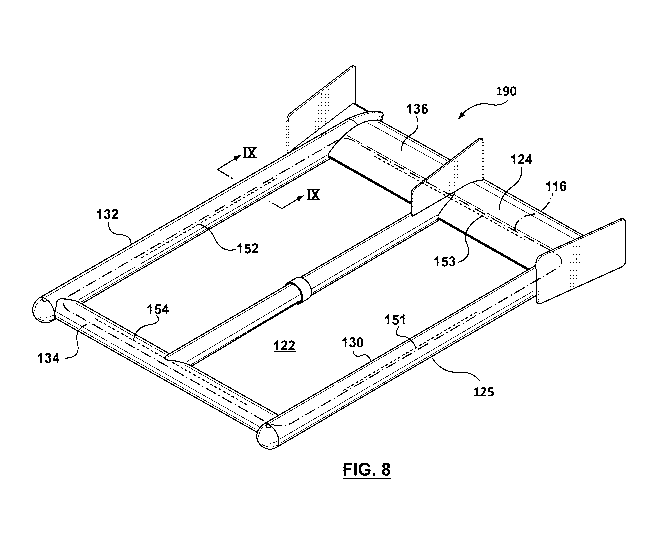
Figures 8-12. The example embodiment of a tow assembly 190 shown in Figure
8 comprises an aerodynamic outer frame or shell 125 with an internal
passageway 124 housing a large vertical sensing axis air coil 116 (illustrated
by
dashed lines) as described in U.S. Patent Application 12/910,386 (US
2011/0115489A1 published 2011-05-19), along with ferromagnetic cored coils
151, 152, 153, 154 (illustrated by dotted lines) which are sensitive to
magnetic
fields in two nominally horizontal directions.
[0074] Although several configurations are possible for shell 125, in
the
illustrated example of Figure 8 the internal passageway 124 extends around the
central open area 122 and air can pass through the central open area 122. The
rectangular receiver coil frame 125 is formed by a pair of parallel tubular
side
frame members 130, 132 interconnected by front and back parallel tubular
frame members 134, 136. In the illustrated embodiment, the tubular side frame
members 130, 132 are longer than the front and back parallel tubular frame
members 134, 136, and vertical stabilizing fins are positioned near the back
or
trailing end of the rectangular receiver coil frame 125 to assist in keeping
the
CA 02873849 2014-11-17
WO 2013/170340
PCT/CA2012/050322
frame oriented in a consistent direction during flight with the receiver air
coil 116
in a nominally horizontal orientation with its axis vertically oriented.
[0075] The cored coils 151, 152 are housed in the tubular side frame
members 130, 132, respectively, and are oriented so that they are sensitive to
the magnetic field component which is substantially along the direction of
flight,
while the cored coils 153, 154 are housed in the front and back tubular frame
members 134 and 136 and are sensitive to the magnetic field component which
is substantially at right angles to the direction of flight. Accordingly, the
cored
coils 151, 152, 153 and 154 are commonly housed with the air coil 116 in the
internal passageway 124, with the air coil 116 extending around the entire
loop
formed by the internal passageway 124, and each of the cored coils 151, 152,
153 and 154 being located in a respective side or region of the internal
passageway 124 immediately adjacent and generally parallel to a respective
region of the air coil 116. The long axis of the core of each of the cored
coils
151, 152, 153 and 154 is parallel to the adjacent turns of the respective
region
of the air coil 116.By way of non-limiting example, the cored coils 151, 152,
153, 154 could be 2.5 m long, the tubular side frame members 130 and 132
could be 4 m long, while the tubular front and back frame members 134, 136
could be 3 m long.
[0076] Cored coils 151, 152, 153, 154, may each, for example be formed
from a single core and solenoid winding as shown in Figure 6. However, the air
coil winding 116 may be flexible (while the core material is rigid and
brittle). To
accomodate flexibility of the air coil 116 region to which it is adjacent,
each of
the cored coils 151, 152, 153, 154 may itself consist of multiple segments.
[0077] By way of example, Figures 12 and 12A illustrate an example of a
multiple segment cored coil that could be used to implement any of coils 151,
152, 153 and 154, with the segments being flexibly attached end to end. As
shown in cross-section Figure 12, for example, the coil core 160, the coil
former
tube 162, and the winding 161 each consist of three segments. The segments of
the winding 161 may be connected in series. Flexible collars 167 connect the
coil former tube 162 segments and keep the axes of the segments aligned, while
allowing bending at the connections. Each core 160 segment is supported and
positioned radially by exactly two elastomeric rings 168 so that bending
stresses
on the coil former tube 162 segments are not transmitted to the core 160
21
CA 02873849 2014-11-17
WO 2013/170340
PCT/CA2012/050322
segments. The core 160 segments are positioned axially by elastomeric spacers
169 which permit bending while preventing axial motion between the adjacent
ends of the core segments. Such a configuration can minimize noise caused by
relative motion between adjacent segments, The flexible attachment assembly
provided by collar 167 and spacer 169 allows bending while maintaining a fixed
distance between the ends of the core segments and maintaining the alignment
so that the extended axes of the core segments intersect at the point midway
between them.
[0078] The use of segmented core coils can also have additional
benefits in
some applications - for example, it may be desirable in some applications to
reduce the weight of the solenoid cored coil receivers 151, 152, 153, 154. At
the same time, the sensitivity of a solenoid cored coil receiver is strongly
dependent on the length of the core, and thus a narrow, long core is
desirable,
however such a core is susceptible to saturation by the geomagnetic field. A
multi-segmented cored receiver such as shown in Figures 12 and 12A can
address these concerns in some applications, with the gaps between adjacent
core segments optimized to obtain maximum sensitivity without excessive
magnetization by the geomagnetic field. By way of non-limiting example, the
core segments could be 0.8 m long and 0.01 m in diameter, with a gap of 0.03
m between adjacent segments.
[0079] It will be appreciated that one cored coil is sufficient to
provide
sensitivity in each of two nominally horizontal directions, so that for
example in
Figure 8, cored coils 151 and 153 could be omitted. Nevertheless, the use of
multiple cored coils for each sensitive direction may reduce the noise level
and
provide for a more symmetrical structure. In some embodiments, there may be
a requirement for sensitivity in just one nominally horizontal direction, so
that
some of the cored coils 151, 152, 153, 154 may be omitted. Vibration of coils
in
the ambient (usually geomagnetic) field is a major source of noise in magnetic
sensors. Motion of a ferromagmetic core in the vicinity of the air coil
receiver is
also a source of noise due to the magnetic field of the ferromagnetic core
which
is induced by the geomagnetic field. Figure 9 shows an example embodiment
assembly 190 in which the cored coils are each independently attached to their
respective region of air coil 116. In particular, Figure 9 shows a cross-
section of
tubular side frame member 132 and the cored coil 152 housed therein attached
22
CA 02873849 2014-11-17
WO 2013/170340
PCT/CA2012/050322
to its respective region of the air coil 116. Cored coils 151, 153 and 154 are
similarly attached to their respective regions of air coil 116, and the
following
description of coil 152 also applies to coils 151, 153 and 154. In the
embodiment
of Figure 9, the combined cored coil 152/ air coil 116 assembly is suspended
at
spaced apart locations along the length of the cored coil 152 by elastic
members
32 from the outer shell 125. This isolates both the cored and air coils from
vibration of the shell 125, while preventing relative motion between the cored
coil 152 and the air coil 116. As noted above, in an example embodiment the
cored coil 152 can includes , for example, core 160, enclosed in a coil former
tube 162 consisting of glass reinforced epoxy or other non-conductive material
upon which is wound coil 161. In an example embodiment the cored coil 152 is
supported in an outer tube 163 which in turn is secured by a fastener or
fasteners such as glue or cable ties to an upper surface of the air coil 116.
In
the illustrated example, the air coil 116 includes one or more turns 165 of
coil
wire enclosed within and supported by an outer tube 166. The cored coil outer
tube 163 is secured along its length by a fastener or fasteners such as glue
or
cable ties to an upper surface of the outer tube 166 that houses the air coil,
such
that the cored coil 152 is rigidly fixed relative to the air coil 116 In the
embodiment of Figure 9, the air coil outer tube 166 is suspended elastically
by
elastic members 32 from the outer shell 125, and in turn supports the cored
coil
152.
[0080] In the example embodiment of Figure 9, the weight of the
solenoid
cored coil 152 is supported by the elastic suspension members 32, so it is
desirable to minimize the weight. The use of a multi-segmented cored coil as
discussed above and as shown in Figures 12 and 12A can mitigate weight
issues.
[0081] Even when the cored coil 152 is rigidly fixed relative to the
air coil
116, rotation of the rigid combined cored coil/air coil assembly can in some
applications induce noise in the air coil 116 due to the changing
magnetization of
the core 160. This effect can be reduced by placing the turns 165 (or groups
of
turns 165) of the air coil 116 symmetrically around the core 160, as shown in
the alternative embodiment of Figure 10. In, particular, in the embodiment of
Figure 10, the cored coil 152 is located within the center of the turns 165 of
the
23
CA 02873849 2014-11-17
WO 2013/170340
PCT/CA2012/050322
air coil 116, and the air coil 116 is supported within outer tube 166 which in
turn
is supported by elastic members 32 from shell 125.
[0082] The example embodiments depicted in Figures 9 and 10 use a
single stage elastic suspension. The same principles can be used with a double
stage elastic suspension as shown in the example embodiment of Figure 11. In
Figure 11, the combined cored coil/air coil assembly is the same as shown in
Figure 10, however the suspension members 32 are supported by a tubular
inner shell or rgid member 74, which in turn is suspended by outer suspension
members 76 from the outer shell 125 .
[0083] In other example embodiments, the outer tubular frame 125 is a
shape other than rectangular - for example, the tubular frame could be
octagonal or other polygonal shape such as shown in Figure 5A, with the cored
coils being located instead at respective locations in the same passageway as
the air coil rather than in cross shaped portion 252 (which can be omitted).
In
such an embodiment, the air coil 116 will be octagonal in shape, with the
octagon lying in a nominally horizontal plane, such that each turn of the coil
follows the perimeter of the octagon; the tubular outer shell 250 forms a
continuous internal passageway which closes back on itself in an octagonal
shape and contains the air coil; an elastic double suspension suspends the air
coil from the outer shell; and at least two cored coils are attached to the
air coil
on two sides of the octagon which are substantially at right angles to each
other.
In at least some example embodiment embodiments, cored coils could be
attached to the air coil in each of the eight sides of the octagonal shell,
with the
signals from the cored coils in the first, second, fifth and sixth sides
providing
one horizontal signal and the signals from the cored coils in the third,
fourth,
seventh and eighth sides providing another horizontal signal. Such a
configuration could in some applications provide greater sensitivity than just
two
orthogonal coils.
[0084] The shape of the loop formed by the outer shell could take a
number of different configurations, and the location and spacing of cored
coils
along the length of the air coil could also take a number of configurations.
In
another example embodiment, the outer tubular frame 125 and the air coil
housed therein is circular, with one or more cored coils extending parallel to
one
or more respective regions of the air coil 116.
24
CA 02873849 2014-11-17
WO 2013/170340
PCT/CA2012/050322
[0085] It will be appreciated that the principles demonstrated in the
example embodiments of Figures 8 -12 can be realized in many different ways
and in different combinations. Features from the embodiments of Figures 1-7
can be combined with and applied to the embodiments of Figuires 8-12 and vice
versa. In some example embodiments, the receiver assemblies decribed herein
may be used in applications other than in towed airborne assemblies, including
for example receiver assemblies fixed to an aircraft or on land based or
marine
receiver assemblies.
[0086] The specific sensors used in the example embodiments described
could be replaced with other types of sensors. In some embodiments, the
rotation motion sensed by a pair of accelerometers oriented in the same
direction but located at opposite sides of a receiver coil assembly could be
detected by a single angular rate sensor. In some embodiments, the
geomagnetic field sensed by a fluxgate magnetometer could instead be
calculated from known models of the Earth's field (such as the International
Geomagnetic Reference Field model) using direction information derived from
two GPS receivers located on the receiver system, or (more approximately) from
track bearing information derived from a single GPS receiver located on the
towing aircraft.
25