Note : Les descriptions sont présentées dans la langue officielle dans laquelle elles ont été soumises.
CA 02873986 2016-06-15
,
BALL SEALER FOR HYDROCARBON RESOURCE COLLECTION AS
WELL AS PRODUCTION METHOD THEREFOR AND DOWNHOLE
TREATMENT METHOD USING SAME
TECHNICAL FIELD
[0001]
The present invention relates to a ball sealer as a tool for
formation or repair of downholes (wellbores) for recovery of
hydrocarbon resources including oil and gas, particularly a ball
sealer (so-called "frac ball") suitable for formation of frac plugs or
frac sleeves (that is, plugs or sleeves for hydraulic fracturing), a
process for production thereof, and a method of processing
wellbores using the ball sealer.
BACKGROUND
[0002]
Downholes (underground drilling pits or wellbores) are
prepared for recovery of hydrocarbon resources including oil and
gas (representatively called "oil" sometimes hereafter) from the
underground, and tools for the formation or repair of the
downholes, such as frac plugs, bridge plugs, cement retainers,
perforation guns, ball sealers, sealing plugs, and packers
(inclusively referred to as "downhole tools" hereafter), are used
and thereafter disintegrated or allowed to fall down as they are in
many cases without recovery thereof onto the ground. (Examples
-1-
CA 02873986 2014-11-18
G07210CAW
of such downhole tools and manners of use thereof are illustrated
in, e.g., Patent documents 1-7). Therefore, about the tool of such
temporary use, it has been recommended to form the whole or a
component thereof constituting a bonding part allowing collapse
(i.e. downhole tool member) with a degradable polymer. Examples
of such a degradable polymer, may include: polysaccharide, such
as starch or dextrin; animal albumin polymers, such as chitin
and chitosan; aliphatic polyesters, such as polylactic acid (PLA,
typically poly L-lactic acid (PLLA)), polyglycolic acid (PGA),
polybutyric acid, and polyvaleric acid; and further, pblyamino
acids, polyethylene oxide, etc. (Patent documents 1 and 2).
[0003]
In order to recover hydrocarbon resources (as represented
by "oil") from surrounding formation through the thus-formed
downholes, hydraulic fracturing (hydraulic pressure or stream
crushing process) is frequently adopted.
[0004]
Conventional ball sealers as mentioned above as an
example of downhole tools used in such a hydraulic fracturing
process, have been used in many cases as sealers or fillers for
directly filling perforations which were formed in the formation
by using perforating gun, etc., for recovery of oils, in order to
suppress the entering of excessive amount of work water into the
perforations (for example, Patent document 6). Ball sealers used
for such purposes generally comprised nondegradable materials,
inclusive of nondegradable resins, such as nylon or phenolic
resin, or aluminum, if needed, coated with rubbery surface layers
-2 -
CA 02873986 2014-11-18
G07210CAW
for improving the sealing performances, and were of relatively
small sizes, e.g., diameters of 16 - 32 mm (5/8 inch - 1.25
inches, as disclosed at col. 2, lines 46 - 48 of Patent document
6).
[0005]
In recent years, however, use of ball sealers having larger
diameters as a part of members forming frac plugs or frac sleeves
(plugs or sleeves for hydraulic fracturing) used in the hydraulic
fracturing process is also proposed. More specifically, a high-
pressure stream is introduced into an operation region defined by
disposing a frac plug formed by a ball sealer together with a ball
sealer at a predetermined position along a downhole prepared in
advance to urge a water stream in a direction perpendicular to
the downhole to fracture the formation, thereby forming
perforations for recovering oils (e.g., Patent documents 1 and 2).
[0006]
Alternatively, there has been also proposed a method of
inserting into a downhole a tube (frac sleeve) in which a plurality
of ball seats have been disposed at predetermined intervals and
successively performing cycles each including supplying and
disposition of a ball sealer at a ball seat, and then introducing a
high-pressure water stream for fracturing the formation to form a
perforation in the frac sleeve (e.g., Patent document 7).
[0007]
Such ball sealers (which are also called "frac balls")
forming a part of such a frac plug or a frac sleeve, are required to
have diameters of, e.g., 25 - 100 mm (1 - 4 inches) in many
-3 -
CA 02873986 2016-06-15
cases, which partly overlap with but are generally larger than the
diameters of the above-mentioned ball sealers for directly sealing
the perforations. However, if such a large-diameter ball sealer is
manufactured by the heat compression molding or injection
molding of not a conventional nondegradable material but of a
biodegradable resin which is crystalline in general, a sink or a
void is developed due to thermal contraction or contraction
accompanying crystallization, so that it was difficult to produce
such large-diameter balls with good dimensional accuracy
required of the frac ball as a member for filling or liquid leakage-
preventing member. For this reason, it has been a present state
that the manufacture of such frac balls of comparatively large
diameters with a biodegradable resin material has been resorted
to a sequence of solidification extrusion .¨ cutting, which is very
complicated and cost-incurring.
PATENT DOCUMENTS
[0008]
[Patent document 1] US2005/0205266A
[Patent document 2] US2005/0205265A
[Patent document 31 US2009/0101334A
[Patent document 4] US7621336B
[Patent document 5] US7762342B
[Patent document 6] US7647964B
[Patent document 7] US2010/0132959A.
- 4 -
CA 02873986 2016-06-15
SUMMARY
[0009]
The present description relates to a production process
capable of forming a ball sealer of a relatively large diameter with
good dimensional accuracy from a polyglycolic acid resin which is
a biodegradable resin with good mechanical strength through
relatively simple steps, and also a ball sealer for hydrocarbon
resource recovery produced as a result thereof.
[0010]
The present description further relates to a method of
processing a wellbore using the above-mentioned ball sealer for
hydrocarbon resource recovery.
[0011]
The ball sealer for hydrocarbon resource recovery of the
present invention may comprise: a generally spherical entire
structure including at least two layers of a spherical core and a
surface resin layer covering the spherical core, of which at least
the surface resin layer comprises a polyglycolic acid resin; and
having a diameter of at least about 25 mm (1 inch).
[0012]
Moreover, the process for producing a ball sealer of the
present invention may comprise the steps of: disposing a
spherical core by a support pin at a substantially central position
within a mold cavity, injecting a surface resin comprising a
polyglycolic acid resin into the cavity surrounding the spherical
core, causing the support pin to retreat up to a wall surface of
mold cavity in synchronism with a completion of the injection of
-5-
CA 02873986 2016-06-15
,
the surface resin, and then hardening the surface resin.
[0013]
Among aliphatic polyester resins showing biodegradability,
polyglycolic acid (PGA) resin shows outstanding mechanical
strength including an especially large compression strength and,
even from this point alone, can be said to have an extremely
excellent characteristic for providing a ball sealer which is built
in a frac plug or a frac sleeve together with a ball seat to function
as a supporting seal member for intercepting a high-pressure
water stream in fracturing (namely, a frac ball). Furthermore, as
notably different characteristics from other aliphatic polyester
resins, such as polylactic acid (PLLA), PGA resin shows a
thickness reduction velocity in water which is constant with time
(in other words, a linear thickness reduction rate (details of
which are disclosed in W02013/183363A), and also
characteristics of, when an inorganic or organic short-fiber
reinforcement material is blended therewith, the initial thickness
reduction rate is suppressed notably, the suppression period is
controllable by the aspect ratio (L/D) of the short-fiber
reinforcement material, and the terminal thickness reduction rate
after a certain degree (e.g., 50 c/o) of thickness reduction
increases notably compared with the initial thickness reduction
rate (the details being disclosed in W02014/010267A). These
characteristics mean that the PGA resin shows advantageous
characteristics for size designing of temporarily used downhole
tool members including a ball sealer, depending on the situation
of use thereof.
-6-
CA 02873986 2016-06-15
[0014]
However, the formation of PGA resin into a large sphere of
about 25 mm or more in diameter, suitable as a frac ball, by the
heat compression molding or the injection molding was very
difficult because of heat shrinkage after the molding, and also a
very large shrinkage during crystallization (solidification) due to
a crystallinity corresponding to the moisture barrier property
which gives the linear thickness reduction rate characteristic in
water, so that the formation of a frac ball requiring a high
dimensional accuracy was difficult. However, noting that the
characteristics of PGA resin associated with the high rigidity and
compression strength required of a frac ball are expected to be
satisfied by the formation of only a surface portion of a frac ball
with a PGA resin, the present inventors thought that the
shrinkage accompanying the solidification of the PGA resin would
not result in lowering in size accuracy unsuitable for an outer
shape of a frac ball product, if the entire frac ball is not formed
in one shot of solidification but only the surface layer is formed
by solidification. Then, the present inventors confirmed that a
large-diameter frac ball of which at least the surface layer
comprised a PGA resin could be formed with good size accuracy
by using a process similar to an insert molding process which
had been applied to surface layer-molding of a golf ball with a
rubbery resin which is contrastive with a crystalline resin, thus
arriving at the present invention.
[0015]
Moreover, the method of processing a wellbore of the present
- 7 -
CA 02873986 2016-06-15
invention may comprise: a cycle of steps including:
feeding a ball sealer along with a working fluid to a ball seat
which has an aperture and has been disposed at a predetermined
position in an elongated frac sleeve inserted into a wellbore
formed in a formation, thereby sealing the aperture to form a seal
section for intercepting the working fluid; and causing the
working fluid to flush through a hole formed in a frac sleeve wall
at a predetermined position right above the seal section, thereby
digging a wellbore inner wall adjacent to the hole to form a
perforation thereat; and then decomposing the frac ball in its
place, wherein the frac ball comprises the above-mentioned ball
sealer according to the present invention.
According to a preferred embodiment, the wellbore processing
method, comprises: disposing a plurality of ball seats at
predetermined intervals in an elongated frac sleeve inserted into
a wellbore, the plurality of ball seats having respective
apertures of respective diameters increasing gradually from a
downstream side to an upstream side of the frac sleeve; and
inserting an elongated frac sleeve into a wellbore; and feeding
into the frac sleeve a work fluid and a plurality of frac balls
having successively increasing diameters to perform fracturing
cycles each including formation of a seal section and formation of
a perforation in a wellbore inner wall successively from the
downstream side, wherein at least a portion of the plurality of
frac balls comprises the above-mentioned ball sealer according to
the present invention.
- 8 -
CA 02873986 2016-06-15
[0015a]
In some embodiment, the present description relates to a frac
ball for use in hydrocarbon resource recovery, the frac ball to be
used in combination with a ball seat placed in a casing in a
wellbore and having an opening smaller than that of the frac ball,
wherein the frac ball has a diameter of at least about 25 mm (1
inch) and a generally spherical entire structure including at least
two layers of a spherical core and a surface resin layer covering
the spherical core, of which at least the surface resin layer
comprises a compression-resistant polyglycolic acid resin having
a weight-average molecular weight of 70,000 to 500,000 and
exhibiting a melt viscosity (JIS-K7199) in the range of 200-1500
Pa-s, when measured under the conditions of a shear rate of
120-sec-1 at a temperature which is the melting point of the
polyglycolic acid resin plus 50 C.
[0015b]
In some embodiment, the present description also relates to
a process for producing a frac ball for hydrocarbon resource
recovery, the frac ball to be used in combination with a ball seat
placed in a casing in a wellbore and having an opening smaller
than that of the frac ball, the process comprising:
disposing a spherical core by a support pin at a substantially
central position within a mold cavity,
injecting a surface resin comprising a compression-resistant
polyglycolic acid resin having a weight-average molecular weight
of 70,000-500,000 and exhibiting a melt viscosity (JIS-K7199) in
the range of 200-1500 Pa-s, when measured under the conditions
- 9 -
CA 02873986 2016-06-15
of a shear rate of 120-sec-1 at a temperature which is the melting
point of the polyglycolic acid resin plus 50 C into the cavity to
form a surface resin layer surrounding the spherical core,
causing the support pin to retreat up to a wall surface of mold
cavity in synchronism with completion of the injection of the
surface resin, and
then hardening the surface resin,
wherein the frac ball has a diameter of at least about 25 mm
(1 inch) and a generally spherical entire structure including the
at least two layers of the spherical core and the surface resin
layer covering the spherical core.
[0015c]
In some embodiment, the present description also relates to
a set of frac balls for hydrocarbon resource recovery, comprising
a plurality of frac balls having different diameters within a range
of about 12.7 mm (0.5 inch) - about 127 mm (5 inches), at least
one of the plurality of frac balls being the frac ball as defined
herein.
[0015d]
In some embodiment, the present description also relates to
a method of processing a wellbore, comprising:
a cycle of steps including:
feeding a ball sealer along with a working fluid to a ball seat
which has an aperture and has been disposed at a predetermined
position in an elongated frac sleeve inserted into a wellbore
formed in a formation, thereby sealing the aperture to form a seal
section for intercepting the working fluid; and
- 9a -
CA 02873986 2016-06-15
causing the working fluid to flush through a hole formed in a
frac sleeve wall at a predetermined position right above the seal
section, thereby digging a wellbore inner wall adjacent to the hole
to form a perforation thereat; and
then decomposing the frac ball in its place,
wherein the frac ball is as defined herein.
[0015e)
In some embodiment, the present description also relates to
a method of processing a wellbore, said method comprising:
disposing a plurality of ball seats at predetermined intervals
in an elongated frac sleeve inserted into a wellbore, the plurality
of ball seats having respective apertures of respective diameters
increasing gradually from a downstream side to an upstream side
of the frac sleeve; and
feeding into the frac sleeve a work fluid and a plurality of
frac balls having successively increasing diameters to perform
fracturing cycles each including formation of a seal section and
formation of a perforation in a wellbore inner wall successively
from the downstream side, wherein at least one of the frac balls
comprises the frac ball as defined herein.
BRIEF DESCRIPTION OF THE DRAWINGS
L00161
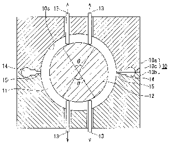
Fig. 1 is a schematic cross section of a mold in an
intermediate stage of frac-ball production by a process of the
present invention.
Fig. 2 is a sectional view of a downhole in which a frac sleeve
- 9b -
CA 02873986 2016-06-15
has been inserted for explaining an example of fracturing work
performed by using the frac sleeve having a ball sealer (frac ball)
of the present invention incorporated therein.
DETAILED DESCRIPTION
[0017]
Hereinafter, the present invention will be described in detail
based on preferred embodiments thereof.
(Polyglycolic acid resin)
The surface layer of the ball sealer for hydrocarbon resource
recovery (frac ball) of the present invention is formed of
polyglycolic acid resin. Polyglycolic acid resin is particularly
preferably used because it has excellent initial strengths as
represented by its compression strength, which is at the highest
- 9c -
CA 02873986 2014-11-18
G07210CAW
level among thermoplastic resins, and also a large effect of
suppressing in-water thickness reduction rate when formed as a
composite material by incorporation of short-fiber reinforcement
material. Polyglycolic acid resin used in the present invention
may include glycolic acid homopolymer (namely, polyglycolic acid
(PGA)) consisting only of a glycolic acid unit (-0CH2-00-) as a
recurring unit, and also a glycolic acid copolymer which includes
other monomer (comonomer) units, such as hydroxycarboxylic
acid units, preferably lactic acid units, in a proportion of at most
50 wt.%. preferably at most 30 wt.%, further preferably at most
10 wt.%. The hydrolysis rate, crystallinity, etc., of polyglycolic
acid resin can be modified to some extent by converting it into a
copolymer including another monomer unit.
[0018]
Polyglycolic acid resin having a weight-average molecular
weight (Mw) of at least 70,000, preferably 70,000-500,000, is
used. If the weight-average molecular weight is below 70,000, the
initial strength characteristics required of a frac ball is impaired.
On the other hand, if the weight-average molecular weight
exceeds 500,000, the polyglycolic acid resin is liable to have
undesirably inferior molding and processing characteristics.
Moreover, in consideration of the injection-molding characteristic,
it is preferred to use one exhibiting a melt viscosity (JIS-K7199)
in the range of 20 to 2000 Pa-s, preferably 200 - 1500 Pa-s, when
measured under the conditions of a shear rate of 120-sec-1 at a
temperature which is the melting point plus 50 C(that is, 270 C
in the case of polyglycolic acid alone).
-10-
CA 02873986 2014-11-18
G07210CAW
[0019]
In order to obtain polyglycolic acid resin of such a
molecular weight or a melt viscosity, rather than polymerization
of glycolic acid, it is preferred to adopt a process of subjecting
glycolide which is a dimer of glycolic acid to ring-opening
polymerization in the presence of a small amount of catalyst
(cation catalyst, such as organo-tin carboxylate, tin halide, or
antimony halide) and substantially in the absence of a solvent
(namely, under bulk polymerization conditions) under heating at
temperatures of about 120-250 . Accordingly,
in case of
forming a copolymer, it is preferred to use as a comonomer one or
more species of lactides, as represented by lactide which is a
dimer of lactic acid, and lactones (e.g., caprolactone, beta-
propiolactone, beta-butyro-lactone).
[0020]
Incidentally, the melting point (Tm) of polyglycolic acid
resin is generally 200 C or higher. For example, polyglycolic
acid has a melting point of about 220 t , a glass transition
temperature of about 38 C, and a crystallization temperature of
about 90 cC. However, the melting point of the polyglycolic acid
resin can vary to some extent depending on the molecular weight
thereof, comonomer species, etc.
[0021]
Although the frac ball of the present invention includes a
surface resin which is usually composed of the polyglycolic acid
resin alone, it is also possible to blend another thermoplastic
resin, such as another aliphatic polyester, an aromatic polyester,
-11-
CA 02873986 2014-11-18
G07210CAW
or an elastomer, for the purpose of controlling the degradability,
etc. However, the blending amount thereof should be suppressed
in amount not obstructing the presence of the polyglycolic acid
resin as the matrix resin required to exhibit a linear thickness
reduction rate, i.e., less than 30 wt.%, preferably less than 20
wt.%, more preferably less than 10 wt.%, of the polyglycolic acid
re sin.
[0022] (Short-fiber reinforcement material)
It is also preferred to blend a short-fiber reinforcement
material with the PGA resin which constitutes the surface of the
frac ball of the present invention. Thereby, as mentioned above,
it is also possible to attain the effect of suppressing the initial
thickness reduction rate in comparison with the PGA-resin alone,
in addition to a reinforcing effect. The short-fiber reinforcement
material may comprise an inorganic or organic fiber
reinforcement material, such as glass fiber, carbon fiber, boron
fiber, aramid fiber, liquid crystal polymer fiber, and cellulosic
fiber (e.g., Kenaf fiber). Among these fiber reinforcement
materials, it is preferred to use one that has a shorter-axis
diameter (D) of 0.1-1000 pm, more preferably 1-100 pm,
particularly preferably 5-20 pm, and an aspect ratio (L/D) of 2-
1000, more preferably 3-300, particularly preferably 3-150, and
that is usually called a milled fiber or a chopped fiber. A shorter
diameter (D) of less than 0.1 pm is liable to fail in providing a
sufficient strength for delaying the collapse and a shorter-axis
diameter in excess of 1000 pm is liable to result in non-uniform
collapse behavior of the shaped body. An aspect ratio (L/D) of
- 12 -
CA 02873986 2014-11-18
G07210CAW
less than 2 fails in providing the effect of collapse delay, and in
excess of 1000, it becomes difficult to uniformly disperse the
short-fiber reinforcement material uniformly by melt-kneading.
There has been also observed a tendency that a larger aspect
ratio (L/D) results in an increased initial suppression period of
thickness reduction rate, whereby it is possible to control, i.e.,
increase or decrease, the initial suppression period of thickness
reduction rate, to some extent.
[0023]
In case of being used, the short-fiber reinforcement
material may preferably be incorporated at a rate of 1 - 50 wt.
parts, more preferably 5 - 45 wt. parts, particularly preferably 10
- 40 wt. parts, per 100 wt. parts of polyglycolic acid resin. Less
than 1 wt. part fails in developing a sufficient strength for
delaying the collapse, and in excess of 50 wt. parts, the uniform
dispersion through melt-kneading of the short-fiber
reinforcement material is liable to be difficult. If the
incorporation amount of the short-fiber reinforcement material is
increased within the above-mentioned range, there is observed a
tendency that the initial suppression period of thickness
reduction rate is increased, so that in combination with the
above-mentioned aspect ratio, it becomes possible to control, i.e.,
increase or decrease, the initial suppression period of thickness
reduction rate.
[0024] (Powdery reinforcement material)
It is also desirable to use a reinforcement material in a
powdery form (in a sense of including particle form) in place of or
- 13 -
CA 02873986 2014-11-18
G07210CAW
in addition to the short-fiber reinforcement material. The
powdery reinforcement material may preferably comprise powder
of inorganic materials, such as mica, silica, talc, alumina, kaolin,
calcium sulfate, calcium carbonate, titanium oxide, ferrite, clay,
glass powder, zinc oxide, nickel carbonate, iron oxide, lime
powder, magnesium carbonate or barium sulfate, having a median
particle size (a particle size giving a cumulative weight of 50 %
counted from either a smaller or larger particle size side) of
about 0.1 pm to lmm, particularly 1 to 100 pm. Compared with
short-fiber reinforcement materials, these powdery reinforcement
materials provide the shaped products with a similar compression
strength-enhancement effect and a better dimensional stability
while the effect of delaying the decomposition is scarce.
[0025]
These powdery reinforcement materials can be used in two
or more species in combination, and can also be used together
with a short-fiber reinforcement material. The amount of addition
(a total amount when used together with a short-fiber
reinforcement material) is 5 to 70 wt.%, preferably 10 to 60 wt.%,
more preferably 15 to 50 wt.%, further preferably 20 to 40 % of
the total amount of the compound including the resin material.
[0026]
It is also preferred that the short-fiber reinforcement
material or the powdery reinforcement material is processed by a
sizing agent or a surface-treating agent, and then mixed with the
resin material. The sizing agent or surface-treating agent may
comprise, e.g., a functional compound, such as an epoxy
- 14 -
CA 02873986 2014-11-18
G07210CAW
compound, an isocyanate compound, a silane compound, or a
titanium compound. These compounds may be applied to the
reinforcement material as a binding treatment or a surface
treatment beforehand, or may be added together with the
reinforcement material simultaneously at the time of preparation
of a resin composition. The reinforcement material can also be
directly melt-kneaded with the whole amount of the polyglycolic
acid resin constituting a shaped body but, if desired, polyglycolic
acid resin composition (master batch) having a higher
concentration of the reinforcement material is prepared
beforehand and is diluted with an additional amount of
polyglycolic acid resin to provide a resin material having a
desired concentration of the reinforcement material. From the
viewpoint of uniform dispersibility of the reinforcement material,
it is preferred that the polyglycolic acid resin is melt-kneaded
with the reinforcement material (and other fillers) to prepare a
pelletized resin material beforehand, which is then supplied to
the molding.
[0027]
The frac ball of the present invention may preferably be
produced by the process of the present invention based on the
insert-molding method. Fig. 1 is a schematic cross section of a
mold 10 in an intermediate stage of the process of the present
invention. A spherical core 12 which has been disposed in a mold
cavity 11 in an open state of a mold 10 including an upper mold
10a and a lower mold 10b is, in a closed state of the mold formed
by joining at an interface 10c, held by a plurality of support pins
- 15 -
CA 02873986 2014-11-18
G07210CAW
13 projected from the upper and lower sides as shown in Fig. 1.
In this state, PGA resin in a molten state is injected through a
runner 14 and a gate 15 of the mold into the mold cavity 11, and,
in synchronism with the completion of injection (namely, almost
simultaneous with or just before the completion of injection), the
front ends of the two or more support pins 13 are retreated from
the respective illustrated core-supporting positions in arrow
directions so as to almost complete the retreatment to the
position on an inner surface lOs of the mold at the time of
completion of the injection.
[0028]
Then, the shaped body is cooled and is caused to
crystallize within the mold. The mold temperature can be any
temperature below the melting point but may preferably be 50-
150 C from viewpoints of cooling rate and crystallization rate. A
temperature below 50 C is accompanied with problems such as
excessively rapid cooling leading to failure of uniform spreading
of the resin at the time of the injection and failure of uniform
property due to a smaller crystallinity of an outer portion than
the inner portion. A temperature above 150 C requires a long
cooling period due to slow crystallization rate.
[0029]
Then, the mold is opened wide and the laminate molded
body is taken out. If needed, the shaped body may be water-
cooled for slight cooling down. Moreover, removal of a residual
strain and equalization of crystallinity can be performed by
carrying out heat treatment at 100-200 C for several minutes to
- 16 -
CA 02873986 2014-11-18
G07210CAW
several hours, if needed. Furthermore, a finishing treatment for
providing a smooth surface may preferably be performed, as
needed, e.g., by polishing for removal of some unevenness
corresponding to the gate 15, some unevenness which can remain
at parts corresponding to support-pins 13, and unevenness
corresponding to the parting line at the interface 10c.
[0030]
The number of the support pins 13 may preferably be
about 3-20, particularly about 3-12, for each of the upper mold
10a and the lower mold 10b. Respective support pins are
desirably disposed so that the front ends thereof may touch
points preferably within an upper surface region or a lower
surface region of the spherical core forming a central angle Ü of
90 degrees. Each support pin may preferably have a shape of a
cylindrical bar having a spherical or slightly elliptical section of
about 0.5-15 mm2.
[0031]
Thus, the frac ball of the present invention is formed by
forming a surface layer of the above-mentioned PGA resin on the
spherical core into a generally spherical shaped body, as a whole,
having a diameter of at least about 25 mm (1 inch), preferably at
least about 32 mm (1.25 inches), particularly preferably at least
about 38 mm (1.5 inches). The upper limit of the diameter is
generally at most about 127 mm (5 inches), preferably at most
about 102 mm (4 inches). Herein, the term "generally spherical"
means that an ellipse having a shorter axis/longer axis ratio of at
least 0.5, preferably at least 0.8, particularly at least 0.9, is not
- 17 -
CA 02873986 2014-11-18
G07210CAW
excluded.
[0032]
The spherical core can also comprise PGA resin, but it is
also possible that only the surface layer governing the property of
a frac ball of the frac ball is formed of PGA resin, and the core
is formed of other biodegradable resins, inclusive of, e.g.,:
aliphatic polyesters other than PGA resin, such as polylactic acid
(PLA, typically poly-L-lactic acid (PLLA)), polybutyric acid and
polyvaleric acid; polysaccharides, such as starch and dextrin;
animal protein polymers, such as chitin and chitosan; and
further polyamino acid, polyethylene oxide, etc. Alternatively, it
is also possible to use a hollow spherical core, as far as a
consideration has been paid so as to retain mechanical strengths,
as represented by a compression strength, of the entire frac ball.
[0033]
To the surface layer-forming PGA resin and the spherical
core-forming biodegradable resin, in addition to the short-fiber
reinforcement material and powder reinforcement material
mentioned above, it is further possible to add various additives,
as desired, within an extent not adverse to the object of the
present invention, inclusive of: thermal stabilizer, light stabilizer,
plasticizer, desiccant, waterproofing agent, water repellent,
lubricant, decomposition accelerator, decomposition retarder,
impact modifier, resin improving agent; mold corrosion
inhibitors, such as zinc carbonate and nickel carbonate;
thermo setting resin, antioxidant, ultraviolet absorber,
nucleating agent such as boron nitride, flame retarder; and
-18-
CA 02873986 2014-11-18
G07210CAW
colorants comprising pigments or dyes.
[0034]
The surface-forming PGA resin layer may preferably have a
thickness in the range of about 2.5-44 mm (0.1-1.75 inches),
more preferably about 3.8-38 mm (0.15-1.5 inches), particularly
about 5.1-32 mm(0.2-1.25 inches). At less than about 2.5 mm
(0.1 inch), there is a possibility that the expected compression
strength may not be obtained in case where only the surface layer
is formed of the PGA resin, and also the shaping efficiency by
insert molding may become worse. On the other hand, in excess
of about 44 mm (1.75 inches), the effect of preventing the
occurrence of a sink or void due to thermal contraction and
contraction accompanying the crystallization achieved by the
thickness suppression of the surface-forming PGA resin layer by
the insert molding as an object of the present invention, will
become scarce.
[0035]
When the thickness of the PGA resin surface layer is
restricted in molding the frac ball of the present invention as
mentioned above, it is possible that the diameter of the spherical
core exceeds the above-mentioned critical value (typically about
mm (1 inch)). In such a case, the spherical core itself can also
be made into a laminated structure by the insert molding
according to the present invention, wherein the surface resin in
25 that case need not be made of PGA resin. In this case, the
laminate core thus formed need not be finished with an excessive
surface accuracy since it is expected to be coated with the PGA
- 19 -
CA 02873986 2014-11-18
G07210CAW
resin surface layer. Apart from the point of surface accuracy,
the formation of such a large-diameter spherical core through a
single step of injection molding is accompanied with problems,
such as a degradation of the resin in the molding waiting state
held in a molten state during successive molding and a
degradation of the resin during an elongated cooling period, and
therefore should desirably be avoided as far as possible.
[0036]
According to one preferred mode of using the ball sealer for
hydrocarbon resource recovery (frac ball) of the present
invention, the ball sealer is used as a portion of frac balls having
plural diameters incorporated in an elongated frac sleeve. A
fracturing work using such an elongated frac sleeve is explained
with reference to a figure. Fig. 2 is a partial sectional view of a
frac sleeve 10 inserted into a downhole D formed in the formation
F, and illustrates a ball seat Bsn disposed at an n-th region, and
a ball seat Bsm disposed at an m-th region (m>n), respectively
counted from the front end of the sleeve. In a fracturing
operation using the frac sleeve, a ball ln having a relatively
small diameter is supplied along with a water stream introduced
in a direction X in the sleeve to be disposed on a ball seat Bsn,
and then a front end of the ball seat Bsn is moved to the position
of a stopper 2n on the downstream due to the hydraulic pressure.
As a result, flush ports 3n which have been covered with a rear
end portion of the ball seat Bn are exposed, and a high-pressure
water streams are flushed through the flush ports 3n to form
perforations 4n at the region Sn.
Subsequently, at a further
- 20 -
CA 02873986 2014-11-18
G07210CAW
upstream region Sm, a ball lm having a large diameter than the
ball ln is supplied, and the above-mentioned fracturing work is
continued. After a series of fracturing operations, frac balls left
behind at regions ...Bsn, Bsm, ... and so on, are expected to
degrade and disappear after prescribed periods depending on the
degradation characteristic of the component resin thereof in the
operation environment.
[0037]
Such a frac sleeve used in a manner as described above is
required to be an elongated one having a length amounting to
hundreds of meters as obtained by joining intermediate tubes in
some cases. As a result, in order to perform continuously a
series of fracturing operations by such an elongated frac sleeve, a
group of many frac balls of different diameters, inclusive of from
about 12.7 mm (0.5 inch) on a smaller side to about 127 mm (5
inches) on a lager side, may be required in some cases.
Accordingly, a preferred application embodiment of the present
invention may be to provide a set of a plurality of frac balls
having different diameters in a range of about 12.7 mm (0.5 inch)
- about 12.7-mm(5 inches) mm, including a portion, preferably at
least a half (and not all), of the plurality, being the frac balls of
the present invention which have a diameter of at least about 25
mm (1 inch) and the laminate structure. The remaining smaller
diameter-side frac balls may preferably be single-layered balls
comprising polyglycolic acid resin.
EXAMPLES
-21-
CA 02873986 2014-11-18
G07210CAW
[0038]
Hereinafter, the present invention will be described more
specifically based on Examples and Comparative Examples. The
characteristic values disclosed in this specification including
Examples described later are based on values measured
according to the following methods.
[0039] <Weight-average molecular weight (Mw)>
For measurement of the weight-average molecular weights
(Mw) of the polyglycolic acid (PGA) and polylactic acid (PLA), each
sample of 10 mg was dissolved in hexafluoroisopropanol (HFIP)
containing sodium trifluoroacetate dissolved therein at a
concentration of 5 mM to form a solution in 10mL, which was
then filtered through a membrane filter to obtain a sample
solution. The sample solution in 10 IAL was injected into the gel
permeation chromatography (GPC) apparatus to measure the
molecular weight under the following conditions. Incidentally, the
sample solution was injected into the GPC apparatus within 30
minutes after the dissolution.
<GPC conditions>
Apparatus: Shimadzu LC-9A,
Column:HFIP-806M x2(series connection)+Pre -column:HFIP-LGx 1
Column temperature: 40 C,
Elution liquid: An HFIP solution containing 5 mM of sodium
trifluoroacetate dissolved therein
Flow rate: lmL/min.
Detector: Differential refractive index meter
Molecular-weight calibration: A calibration curve was prepared by
- 22 -
CA 02873986 2014-11-18
G07210CAW
using five standard molecular weight samples of polymethyl
methacrylate having different molecular weights (made by
POLYMER LABORATORIES Ltd.) and used for determining the
molecular weights.
[0040] <Melt viscosity>
The melt viscosity of polyglycolic acid was measured as follows
based on JIS-K7199. An orifice with a diameter of 1 mm and a
length of 10 mm was set to a semi-automatic capillary rheometer
(made by Yasuda Seiki Seisakusho, Ltd.) and after a temperature
increase to 270 C , a sample resin having been fully dried in
advance was charged into the cylinder. After a preheating for 300
seconds, a viscosity was measured at a shear rate of 120 sec-1.
[0041] (Example 1)
Polyglycolic acid (PGA) (melt viscosity: 600Pa-s@270 ,
120 second -1 , made by Kureha Corporation) was supplied to an
injection molding machine ("SAV-100-75", made by Sanjo Seiki
Seisakusho K.K.) and melt-kneaded at a cylinder temperature of
250 , to
prepare a PGA ball of 0.5 inch (about 13 mm) in
diameter by a mold (an ordinary split mold having a horizontal
joining boundary for injection molding) set at 100 r .
Subsequently, the above-prepared 0.5 inch-dia. PGA ball 12 was
disposed as a core on three cylindrical support pins 13 each
having a cross section of 1.5 mm2 in a lower mold 10b of a mold
10 for vertical insert-injection as shown in Fig. 1, and an upper
mold 12b equipped with similarly three support pins 13 was
caused to descend to close the mold, thereby holding the PGA-
ball core 12 at a substantially central position in the resultant
- 23 -
CA 02873986 2014-11-18
G07210CAW
cavity 11. In this state as shown in Fig. 1, the mold temperature
was set to 100 C and the same PGA as the above was supplied to
the vertical injection molding machine to be melt-kneaded at a
cylinder temperature of 250 C and injected into a 1.5 inch-dia.
cavity 11 of the above-mentioned mold. Then, almost simul-
taneously with completion of the injection, the support pins 13 of
the upper and lower molds were retreated to the inner surface
positions of the mold. After the completion of injection, the
product was cooled for 35 sec. while kept in the mold, and then
the mold was open to recover a 1.5 inch-dia. laminate ball formed
by insert molding, which was free from deformation due to sink
as a result of visual observation. Moreover, when some of a
plurality of lamination balls thus prepared were cut into halves
to observe the insides, voids were not recognized. Unevenness on
the obtained lamination ball corresponding to the gate, parting
line and support pins of the mold, was removed by a cutter and
polished to be smoothed.
[0042] (Example 2)
A ball of 1.5 inches in diameter was prepared by insert molding
as in Example 1, and then insert molding was again performed in
the same manner as in Example 1 except for using the 1.5-inch
ball as a spherical core 12 and using a mold 10 having a cavity of
2.5 inches in diameter for the insert molding.
[0043] (Example 3)
Insert molding was performed in the same manner as in
Example 1 except for using as a surface layer material a 70/30
(by weight) mixture of the same PGA and a glass fiber (GF) ("GL-
- 24 -
CA 02873986 2014-11-18
G07210CAW
HF" made by Owens Corning; shorter-axis diameter: 10 pm, fiber
length: 3 mm) to obtain a 1.5 inch-dia. laminate ball having a
core of PGA alone and a surface layer of glass fiber (GF)-
incorporated PGA.
[0044] (Example 4)
Insert molding was performed in the same manner as in
Example 1 except for using as a core-forming material a
polylactic acid (PLLA, "4032D" made by Nature Works LLC, Mw
(weight-average molecular weight): 260,000, Tmp (melting point):
170 C) instead of PGA to obtain a 1.5 inch-dia. laminate ball
having a core of PLLA alone and a surface layer of PGA.
[0045] (Example 5)
Insert molding was performed in the same manner as in
Example 1 except for using as a surface layer material a 70/30
(by weight) mixture of the same PGA and glass powder ("ASF-
1340" by Asahi Glass Co. Ltd.; average particle size: 2 pm) to
obtain a 1.5 inch-dia. laminate ball having a core of PGA alone
and a surface layer of glass powder (GP)-incorporated PGA.
[0046] (Example 6)
Insert molding was performed in the same manner as in
Example 1 except for using a 70/30 (by weight) mixture of the
same PGA and a milled glass fiber (MF) ("EHF50-3" made by
Central Glass Co. Ltd.; shorter-axis diameter: 11 pm , average
fiber length: 50 pm) instead of PGA alone as a core material and
a surface layer material to obtain a 1.5 inch-dia. laminate ball
having a core and a surface layer, both made of milled glass
fiber(MF)-incorporated PGA.
- 25 -
CA 02873986 2014-11-18
G07210CAW
[0047] (Comparative Example 1)
A 1.5 inch-dia. ball made of a single layer of PGA alone
was formed in the same manner as the preparation of the core
PGA ball in Example 1 except for using the same PGA alone used
in Example 1 as a sole molding material and an injection mold
with an increased cavity diameter of 1.5 inches. A cooling time
of 35 sec. was taken similarly as in Example 1 but the ball taken
out of the mold was hot and therefore further cooled by dipping
in water. The resultant ball was deformed by sink and, as a
result of cutting into halves and observation of the interior, voids
. of about 1 cc were observed.
[0048]
The outline of the above-mentioned Examples and Comparative
Example is summarized in the following Table 1.
[Table 1]
. . . . ' .
Example 1 2 3 4 5 6 Comp. 1
Core PGA PGA PGA PLA PGA PGA/MF PGA
. r r r r r r
Diameter (inch) 0.5 0.5 0.5 0.5 0.5 0.5 1.5
r
Cooling time (second) 35 35 35 35 35 35
35+
cooling ng
Surface layer
PGA (PGA) PGA/GF PGA PGA/GP PGA/MF ¨
(Interlayer)
. r
P r =
Thickness (inch) 0.5 0.5 0.5 0.5 0.5 0.5
r r r
r r .
Cooling time (second) 35 35 35 35 35 35
Surface layer PGA ¨ ¨ ¨ ¨
P
Thickness (inch) 0.5 ¨ ¨ ¨ ¨
P
Cooling time (second) ¨ 35 ¨ ¨
P r r r . P r
Final diameter (inch) 1.5 2.5 1.5 1.5 1.5 1.5 1.5
Appearance Good Good Good Good Good Good Void,
sink
- 26 -
CA 02873986 2014-11-18
G07210CAW
[Industrial applicability]
[0049]
As described above, the present invention allows production of
a large-diameter ball sealer suitable for use in the hydraulic
fracturing process (hydraulic fracturing) widely used for recovery
of hydrocarbon resources by using a polyglycolic acid resin which
is a biodegradable resin having good mechanical strengths and a
good size designability at least as a surface-forming resin,
through relatively simple steps and with good dimensional
accuracy. ,
- 27 -