Note : Les descriptions sont présentées dans la langue officielle dans laquelle elles ont été soumises.
CA 02875028 2014-11-27
259185
1
GAS TURBINE ENGINE WALL
BACKGROUND OF THE INVENTION
[0002] The field of the invention relates generally to turbine engines,
and more specifically to film cooling of turbine engines.
[0003] In a gas turbine engine, air pressurized in a compressor is
mixed with fuel in a combustor to generate hot combustion gases. Energy is
initially
extracted from the gases in a high pressure turbine (HPT) that powers the
compressor,
and subsequently in a low pressure turbine (LPT) that powers a fan in a
turbofan
aircraft engine application, or powers an external shaft for marine and/or
industrial
applications.
[0004] Generally, engine efficiency increases as the temperature of
combustion gases is increased, but the increased gas temperature increases the
operating temperature of various components along the gas flowpath, which in
turn
increases the need for cooling such components to facilitate extending their
useful
life.
[0005] For example, known combustors include outer and inner liners
which require cooling during operation. Known turbine nozzles include hollow
vanes which also require cooling. In at least some turbine engines, flowpath
components exposed to hot combustion gases are cooled using compressor bleed
air,
which subsequently reduces engine efficiency since the bled air is not used in
the
combustion process. For example, at least some known components channel the
compressor bleed air through film cooling holes.
CA 02875028 2014-11-27
WO 2013/188645
PCT/US2013/045619
2
[0006] At least some known cooling holes are formed from a
cylindrical bore that is oriented at a shallow angle through the heated wall
to enable a
film of cooling air to be discharged along the external surface of the wall.
Discharging
the air at a shallow angle reduces the likelihood of undesirable blow-off
and/or flow
separation. The amount of surface area to be film cooled is typically only
increased by
increasing the number of cooling holes and thus increases the amount of air
discharged therefrom. However, increasing the amount of cooling air decreases
engine efficiency.
[0007] To improve the efficiency of known cooling holes, at least
some cooling holes are formed with a divergent discharge end to diffuse the
cooling
air as it is discharged from the cooling hole outlet.
[0008] However, diffusion in film cooling holes may be limited due
to the half-angle of the diffusion outlet to prevent flow separation. For
example,
within known cooling holes, the diffusion angle may be limited to about ten
degrees
on each side of the outlet to prevent overexpansion of the discharge cooling
air which
could lead to undesirable film separation.
[0009] Accordingly, it is desired to provide an improved film cooling
hole that can produce increased film coverage without increasing the amount of
cooling air required and without increasing the likelihood of flow separation
of the
film cooling air.
BRIEF DESCRIPTION OF THE INVENTION
[0010] In aspect, a gas turbine engine wall is provided. The wall
includes an inner surface and an opposing outer surface having at least one
film
cooling hole defined therein. The at least one film cooling hole includes an
inclined
inlet bore that extends from the inner surface and a pair of channels that
diverge
laterally from an outlet end of the inclined inlet bore. The pair of channels
have a
substantially constant width and are separated by a ridge to form a boomerang
cross-
sectional shape.
CA 02875028 2014-11-27
WO 2013/188645
PCT/US2013/045619
3
[0011] In another aspect, a gas turbine engine wall is provided. The
wall includes an inner surface and an opposing outer surface having at least
one film
cooling hole defined therein. The at least one film cooling hole comprises an
inclined
inlet bore that extends from the inner surface and a pair of channels that
diverge
laterally from an outlet end of the inclined inlet bore. The pair of channels
have a
substantially planar floor and are separated by a ridge to form a boomerang
cross-
sectional shape.
BRIEF DESCRIPTION OF THE DRAWINGS
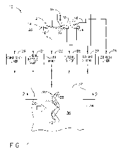
[0012] FIG. 1 is a schematic view of an exemplary gas turbine
engine including various components that are cooled by a row of boomerang film
cooling holes;
[0013] FIG. 2 is a cross-sectional view through one of the
boomerang cooling holes illustrated in FIG. 1 and taken along line 2-2;
[0014] FIG. 3 is an axial view of the boomerang cooling hole shown
in FIG. 2 and taken along line 3-3;
[0015] FIG. 4 is a cross-sectional view of the boomerang outlet
shown in FIG. 3 and taken along line 4-4;
[0016] FIG. 5 is a cross-sectional view of an alternative film cooling
hole that may be used with the gas turbine engine shown in FIG. 1;
[0017] FIG. 6 is an axial view of the cooling hole shown in FIG. 5
and taken along line 6-6;
[0018] FIG. 7 is a cross-sectional view of the outlet shown in FIG. 6
and taken along line 7-7;
[0019] FIG. 8 is a plan view of one of the boomerang cooling holes
shown in FIG. 1 and normal to the wall being cooled;
CA 02875028 2014-11-27
WO 2013/188645
PCT/US2013/045619
4
[0020] FIG. 9 is a plan view of one of the cooling holes shown in
FIG. 5 and normal to the wall being cooled.
[0021] FIG. 10 is a cross-sectional view of an exemplary deep
boomerang film cooling hole;
[0022] FIG. 11 is a plan view of the boomerang hole shown in FIG.
and normal to the wall being cooled;
[0023] FIG. 12 is an axial view of the boomerang hole shown in FIG.
10 and taken along line 12-12;
[0024] FIG. 13 is an illustration of an alternative row of cooling
holes that may be used with the wall shown in FIG. 1.
[0025] FIG. 14 is an enlarged axial view of the boomerang film
cooling holes of FIG. 1; and
[0026] FIG. 15 is an isometric view of the boomerang outlets shown
in FIG. 14.
DETAILED DESCRIPTION OF THE INVENTION
[0027] FIG. 1 is a schematic view of an exemplary turbine engine 10
that includes a longitudinal or axial centerline axis 12. In the exemplary
embodiment,
engine 10 is a gas turbine engine that includes in serial flow communication,
a fan 14,
a multistage axial compressor 16, and an annular combustor 18. Engine 10 also
includes a high pressure turbine (HPT) 19 and a low pressure turbine (LPT) 24
that
are each downstream from combustor 18.
[0028] HPT 19 includes a turbine nozzle 20 having a row of hollow
stator vanes (not shown) supported in inner and outer nozzle bands 23. A first
stage
turbine 22 is downstream from first stage turbine nozzle (not shown) and
includes a
row of hollow rotor blades 25 that extend radially outwardly from a supporting
rotor
disk (not shown) and that are surrounded by an annular turbine shroud 27.
CA 02875028 2014-11-27
WO 2013/188645
PCT/US2013/045619
[0029] Low pressure turbine (LPT) 24 is coupled downstream from
high pressure turbine 19 and includes additional nozzles and rotor blades (not
shown)
which may or may not include internal cooling circuits depending upon the
engine
design. An exhaust liner 26 extends downstream from low pressure turbine 24.
[0030] Each component to be cooled, i.e. liner 26, includes at least
one wall 32 formed from a thin metallic material. More specifically, wall 32
is
typically formed of a conventional superalloy metal, such as a cobalt-based
material
that has a high strength at the elevated temperatures experienced during
operation of
turbine engine 10 and that can withstand the heating generated by exposure to
hot
combustion gases 30.
[0031] During operation, ambient air is pressurized by fan 14 to form
pressurized air 28. A lower portion of air 28 enters compressor 16 for
additional
pressurization while another portion of air 28 is discharged from a fan outlet
to
provide propulsion thrust in a turbofan engine application (not shown). Air 28
discharged from the compressor 16 is mixed with fuel in combustor 18 to
generate hot
combustion gases 30. Combustion gases 30 flow downstream through various
turbine
blade stages which extract energy therefrom to power compressor 16 and fan 14
during turbine operation.
[0032] Engine 10 may have any conventional configuration and
operation, and as such, the invention described herein is not limited to only
being used
with engine 10. Rather, any one or more of the various engine components
disclosed
herein, or any component subject to heating from combustion gases 30 may be
used
with the invention described herein. More specifically, any component
requiring
cooling that includes a wall 32, a portion of which is illustrated in FIG. 1,
may be
cooled by the invention described herein.
[0033] Wall 32 includes opposite inner and outer wall surfaces 34
and 36, respectively. Inner or inboard surface 34 forms an outer boundary of a
suitable cooling circuit formed in wall 32 and receives pressurized air from
CA 02875028 2014-11-27
WO 2013/188645
PCT/US2013/045619
6
compressor 16. Outer surface 36 is exposed to high temperature combustion
gases 30
during operation and requires suitable film cooling protection.
[0034] Wall 32 may be a portion of inner or outer combustor liners
29, a portion of turbine nozzle vanes 31, a portion of turbine nozzle bands
23, a
portion of turbine rotor blades 25, a portion of turbine shroud 27, and/or a
portion of
exhaust liner 26.
[0035] In the exemplary embodiment, cooling holes 38 are arranged
in a suitable row that is oriented along a span of wall 32. More specifically,
in the
exemplary embodiment, film cooling holes 38 each have a boomerang
configuration.
[0036] FIGS. 2-4 illustrate views of cooling hole 38. In the
exemplary embodiment, each hole 38 extends longitudinally through wall 32 and
diverges both longitudinally along hole 38 and laterally across a width, or
thickness t,
of hole 38 between an inlet 40 and an outlet 42. In the exemplary embodiment,
inlet
40 is substantially flush with inner surface 34, and outlet 42 is
substantially flush with
outer surface 36. Each hole 38 includes a substantially cylindrical inlet bore
44 that
defines a substantially constant flow area between its inlet end 40 and its
outlet end
46. Bore 44 is oriented at an angle or is inclined relative to wall 32 at an
inclination
angle A. Angle A may be any angle that enables hole 38 to function as
described in
more detail herein, such as, for example, between 20 and 45 .
[0037] In the exemplary embodiment, bore 44 terminates at its outlet
end 46 in a pair of legs or channels 48 that extend outwardly to wall outer
surface 36.
Channels 48 are separated by a ridge 50 that has a substantially constant
lateral width
Y (shown in FIG. 8). Ridge 50 is spaced a distance G (shown in FIG. 2) from
outlet
end 46 and decreases in depth as ridge 50 extends towards wall outer surface
36.
[0038] In the exemplary embodiment, each channel 48 is at least
partially defined by an arcuate or rounded floor 52 that has a substantially
constant
width X and by a sidewall 54 that extends from rounded floor 52 to ridge 50.
Alternatively, channel width X increases with distance from outlet end 46 at
any angle
that enables hole 38 to function as described herein. Floor 52 also defines an
outer
CA 02875028 2014-11-27
WO 2013/188645
PCT/US2013/045619
7
edge 70 of boomerang outlet 42. Channels 48 diverge from each other at outlet
end
46 at an angle DFA and in the exemplary embodiment, are substantially
symmetrical.
Channels 48 diverge from each other at ridge 50 at an angle DFA2. Angles DFA
and
DFA2 (shown in FIGS. 8 and 9) may be any angle that enables hole 38 to
function as
described herein, such as, for example, between about 20 to about 1000
.
[0039] In the exemplary embodiment, inlet bore 44 is oriented at an
oblique angle A relative to wall inner surface 34, along which it receives
pressurized
air 28 (shown in FIG. 1) from compressor 16 to facilitate cooling wall 32
during
operation. As shown in FIG. 2, channels 48 diverge longitudinally between bore
outlet end 46 and wall outer surface 36 as represented by the difference in
inclination
angle B of ridge 50 and the inclination angle C of floor 52.
[0040] In the exemplary embodiment, channels 48 decrease in depth
F between inlet bore 44 and boomerang outlet 42 such that each channel 48 is
substantially flush with wall outer surface 36. Moreover, holes 38 increase in
area, i.e.
their flow area, from inlet bore 44 to boomerang outlet 42 along wall outer
surface 36
such that the flow area is distributed within channels 48 to facilitate
diffusing
pressurized air 28. As such, the discharged film cooling air is discharged
from holes
38 and spread generally laterally across width E prior to the flow
encountering
combustion gases 30 downstream from outlet 42.
[0041] Channels 48 diverge from ridge 50 such that a depth of each
increases over the axial length of ridge 50 as a result of the difference in
inclination
angles B and C. In one embodiment, inclination angle A of inlet bore 44 is
between
about 20 to about 45'; whereas inclination angle B of ridge 50 is smaller
than
inclination angle A such that ridge 50 intersects wall outer surface 36 at a
shallower
discharge angle than inlet bore 44. Moreover, in the exemplary embodiment,
inclination angle C is smaller than inclination angle B and intersects wall
outer
surface 36 at an even shallower discharge angle adjacent to a trailing edge 72
of
boomerang outlet 42 to facilitate reducing blow-off and/or separation of
pressurized
air 28.
CA 02875028 2014-11-27
WO 2013/188645
PCT/US2013/045619
8
[0042] Referring again to FIGS. 3 and 4, channels 48 diverge from
common inlet bore 44 to trailing edge 72. Each channel 48 is defined by a
substantially constant width X that may be substantially equal to a diameter D
of inlet
bore 44. As best seen in FIG. 4 of the exemplary embodiment, channels 48
extend
deeper into wall 32 than ridge sidewalls 54 such that a half-teardrop
configuration is
defined by channels 48 and sidewalls 54. Ridge 50 is a distance G from outlet
end 46.
Alternatively, ridge 50 may be at any relative distance from outlet end 46
and/or may
be defined at outlet end 46.
[0043] In the exemplary embodiment, boomerang outlet 42 increases
in lateral width E longitudinally along ridge 50 as ridge 50 decreases in
depth F from
outer surface 36. Moreover, in the exemplary embodiment, channels 48 and ridge
50
increase lateral width E of boomerang outlet 42 and lateral width E may be
selected to
facilitate optimizing diffusion of discharged pressurized air 28 by separating
the flow
of the air at ridge 50. Pressurized air 28 is separated by ridge 50 and flows
over
sidewalls 54 and past rounded floors 52 to facilitate diffusion of air 28 and
to provide
a film of cooling air over wall outer surface 36.
[0044] As such, in the exemplary embodiment, the diffusion of
pressurized air 28 discharged through inlet bore 44 is facilitated in
boomerang outlets
42 as air 28 is spread laterally by channels 48, particularly at higher
blowing ratios. A
substantial increase in film cooling coverage may be obtained by varying
lateral width
E of boomerang outlet 42 to facilitate improved attachment of air 28 along
wall outer
surface 36 at discharge angles B and C.
[0045] FIGS. 5-7 illustrate an alternate embodiment of a cooling
hole, known as a maximo cooling hole 60 that is similar to hole 38 (shown in
FIGS.
1-4). In the exemplary embodiment, maximo cooling hole 60 includes a pair of
channels 62 that are each defined by substantially planar floors 64. Moreover,
each
channel 62 includes a pair of rounded sidewalls 66 and 68 that each extend
from
opposite sides of planar floors 64. Moreover, sidewalls 66 define an outer
edge 70 of
hole outlet 42 and are each substantially perpendicular to wall outer surface
36.
Moreover, sidewalls 68 extend from planar floors 64 to form ridge 50.
CA 02875028 2014-11-27
WO 2013/188645
PCT/US2013/045619
9
[0046] Sidewalls 68 are formed with a steeper incline than sidewalls
54 (shown in FIG. 4) and channels 62 are substantially symmetrical. Moreover,
channels 62 diverge at an angle DFA3 that is smaller than diverging angle DFA
of
channels 48 (shown in FIGS. 8 and 9). In the exemplary embodiment, ridge 50 is
defined at a distance G from outlet end 46 and decreases in depth from outlet
end 46
to outlet 42 in an arcuate profile. In other embodiments, ridge 50 may be
substantially linear and/or may extend to outlet end 46.
[0047] In the exemplary embodiment, channels 62 increase in width
between bore outlet 46 and outlet 42 to facilitate diffusing pressurized air
28 (shown
in FIG.1) discharged from outlet 46. Air 28 discharged from outlet 46 is
separated by
ridge 50 and is forced through channels 62 wherein the air is diffused by
diverging
channels 62. Diffused air 28 flows over sidewalls 68 and along a trailing edge
72 of
outlet 42. Generally, inclination of the curve of ridge 50 is less than
inclination angle
A, and inclination angle C of channels 62 is shallower than the inclination of
ridge 50
to facilitate increased flow attachment and reduced blow-off as air 28 flows
past outer
wall surface 36, as compared to air discharged at angle A.
[0048] FIGS. 8 and 9 are additional views of hole 38 and maximo
hole 60, respectively. More specifically, FIG. 8 is a plan view of hole 38
taken
substantially normal to wall outer surface 36, and FIG. 9 is a plan view of
maximo
hole 60 taken substantially normal to wall outer surface 36.
[0049] FIGS. 10-12 each illustrate an alternative embodiment of the
boomerang configuration designated as a deep boomerang hole 80. Cooling hole
80
is similar to hole 38 except that channels 48 each have an increased depth as
compared to cooling hole 38, as shown by the difference in inclination angles
C
(shown in FIGS. 2 and 10).
[0050] FIG. 13 illustrates an alternative row 37 of cooling holes 38
that may be used with wall 32. In the exemplary embodiment, cooling hole 38
includes a centerline axis 53, a first channel 49, and a second channel 51.
Channels
49 and 51 diverge from ridge 50 and are positioned on opposing sides of
centerline
CA 02875028 2014-11-27
WO 2013/188645
PCT/US2013/045619
axis 53. Further, a transverse axis 55 extends in a transverse direction
relative to a
flow direction of cooling gases 30.
[0051] In the exemplary embodiment, cooling hole 38 is rotated
about at least one axis to facilitate changing an orientation of cooling hole
38. For
example, cooling hole 38 is rotated such that an angle I is defined between
centerline
axis 53 and transverse axis 55, and is rotated about centerline axis 53 in a
hoop
direction J. As such, changing the orientation of cooling holes 38 facilitate
changing
a depth of each first channel 49 and second channel 51 within wall 32, and
facilitate
aligning each trailing edge 72 of channels 49 and 51 along transverse axis 55.
Aligning each trailing edge 72 enables a substantially uniform flow of
pressurized air
to be discharged from cooling holes 38. In some embodiments, the degree of
rotation
to be applied cooling hole 38 in hoop direction J may depend upon angle I of
centerline axis 53 relative to transverse axis 55. More specifically, the
degree of
rotation may be modified to facilitate aligning each trailing edge 72 along
transverse
axis 55.
[0052] FIGS. 14 and 15 illustrate additional parameters of hole 38
and Table 1 describes an exemplary range of parameters of cooling hole 38.
More
specifically, in Table 1, t represents the thickness t (shown in FIG. 2) of
wall 32, A
represents the through hole inclination angle A (shown in FIG. 2), and C
represents
the layback surface angle i.e., inclination angle C (shown in FIG. 2), at
which channel
48 intersects wall outer surface 36. D represents the diameter D (shown in
FIG. 2) of
inlet bore 44 and L represents the length L (shown in FIG. 2) of inlet bore
44. L2
represents the length L2 (shown in FIG. 2) of hooded diffusion or a distance
from
outlet end 46 that hole 38 is covered or shielded by wall outer surface 36.
When hole
38 is viewed through inlet bore 44, H represents the total height H of hole
38, H2
represents the height H2 of ridge 50, W represents the upstream width W of
hole 38,
and E represents lateral width E (shown in FIGS. 3 and 6). Further, DFA
represents
the diffusion angle DFA (shown in FIG. 8) of the outboard edges of channels
48, and
DFA2 represents the diffusion angle DFA2 (shown in FIG. 8) of the inboard
edges of
channels 48, which also represents the angle at which channels 48 diverge. P
CA 02875028 2014-11-27
WO 2013/188645
PCT/US2013/045619
11
represents the distance P (shown in FIG. 8) between the centers of adjacent
holes 38
and is used to determine air coverage produced by hole 38.
. Nominal
Param Min Max
Value
t (mils) 15 30 Any
A (deg) 0 30 90
B (deg) 0 10 90
C (deg) 0 10 30
D (mils) 0 12 Any
L/D 0 0.5 Any
L2/D 0 2.8 Any
P/D 4.2 Any
L (mils) 0 6 Any
L2 (mils) 0 33.2 Any
H (mils) 0 26 Any
H2 0 14 Any
(mils)
H3 0 33 Any
(mils)
E (mils) 0 48 Any
I 0 45 Any
J 0 30 90
W (mils) 0 24 Any
W2 0 12 Any
(mils)
DFA 0 46 180
(deg)
DFA2 0 75 180
(deg)
Coverage 10% 95% 100%
(W/P)
Table 1.
[0053] Table 2 describes exemplary parameters of hole 38, maximo
hole 60 and deep boomerang hole 80, respectively.
CA 02875028 2014-11-27
WO 2013/188645
PCT/US2013/045619
12
Deep
Param Boomerang Maximo Boomerang
t (mils) 30 30 30
A (deg) 30 30 30
B (deg) 10 15 15
D (mils) 12 12 12
L/D 0.5 0.5 0.5
L2/D 2.8 2.8 2.8
P/D 4.2 8.4 8.4
L (mils) 6 6 6
L2(mils) 33.2 33.2 33.2
Table 2.
[0054] Tables 3-7 describe a performance ETAAvG of hole 38,
maximo hole 60 and deep boomerang hole 80 compared to known hole shapes such
as
the standard axial shaped hole (ASH), the chevron, the compound angle shaped
hole
(CASH), the wide ASH, and the deep ASH. Performance ETAAvG is a measure of
film effectiveness, i.e. how well the flow exits each hole and protects wall
outer
surface for a given blowing ratio M. Tables 3-7 describe performance ETAAvG at
blowing ratios M of 1, 1.5, 2, 3 and 4, respectively. In Tables 3-7, A vs base
is a
measurement of performance ETAAvG versus the standard ash hole, which is used
as a
baseline comparison. COVB represents coverage of the specified shape and LBA
represents layback angle B. As shown in Tables 3-7, hole 38, maximo hole 60
and
deep boomerang hole 80 show marked improvements in performance ETAAvG over
existing shapes, particularly at higher blowing ratios M of 2, 3 and 4.
m ErkwG -1 eftgline &cola
NUM .CONRG lETA2,1 A vs BASE COVE LEA DPA
E-IXA:FRA!.iGi3 23% a53.5
STD ildS3i 0.23.65 0.0% a415.5 10
2 :SRC LliEt;,F.SN 0.3.351 -1.0% ,L145E., 10
7 ihME ASI-t 0.1'27F, 0.E55
03C-4 15 3;3,
4
8 Dffp:ozi-i a:1055 -22.7% 15
Table 3.
CA 02875028 2014-11-27
WO 2013/188645
PCT/US2013/045619
13
-.N.."
NI = IS ETA:l.v...; - I' :engine scate
Num .CONFt6 ETAw..3 A vs B,.A.SE COVB LBA DF.,i4
3 2:{Kmaas a1744 5.4% 0...535
7 I.Ai:DE AS1i 111572 1.0% Cs...535 1,5 30
6 DEETBOINMER C.,- 1557 Ø2% Cs...';', 15
1 nT,....Uti 11E55 as.:s%
E2.'1 -2.1.;?.= 0.4E45 1,3 20
Nc:e.,,x:im,I3 0.15,52 -3.25 3..8.54 15 33
4 CASH :1357 -1.331% :-$.5F.,5 10 23
8 DE4345.1; iD.1140 -13.0,;?.= 0.540 15 20
Table 4.
m - 2 ET.Ai.tiG: - .1' .engiine szalie
NUM CONPPG ETAAso.- A vs BASE .00VB LBA Dr-A
5 5CaMERANG a.1S20 10.3% 0.535 IQ =-.7
6 5E1" iBCOMER 0-1'302 5.3% .Ø54 15 30
atsss 5.5:.- 0.555 I.f.,, 5.,i)
5 mamo Cs..1877 7..:9,% a'.5:34 15 30
1 s751-? Cs.174G .C.:35;:.: C.:.45i5 1.0
2: C,RC CiiaM_-;1; '0,1_6.93-2.7% a4E...;.i IG 2:3
0..1.455 -i5 0.55E 10 13
8 Da--pAS1-; al477 -15.1% 0.54-c. 15 10
Table 5.
3 ETA AvG -1.' :engine: scek
Num comnie ETA,4,,G, A. v5 BASE COY:3 LBA DFA
.5 iv...ma,co. 0.1214 4:1..CS 0.534 15 3:1".=
7 ,,,WGE,ASI- 0.2.05'S :311:% 0.535 13 33
5 3=Pp WC/MR i]'..2...5S:g 5i3.1:5;i= .-.1'...E.::04
15 30
3 BsswiERAw.-: 02C.:04 17.1% 0.535 10 s::::::
2 sFyi C3-tnn +0.13E43 Q. 0.55 10 20
1. ism i 0.1577 3.05 0..4,..R5 10 20
4 ciasii Ø1545 -1.0 :0.555 1.0 1S'õi
a SEEP AN-i: 0.133.3. -2.35 F.S.45* 13 2,D
Table 6.
CA 02875028 2014-11-27
259185
14
- 4 ETAAv13 ¨ 1" engine .scale
NUM CQNFl1 ETAm;G A vs BASE COVB LBA DFA
mAximc 2.2557 55.5 2.5,24 15 32
7 wiDo ASH 2.22E5 Lq22.635
6 DEEP &DOME; 2.2157 39.6% 0.52415
E.DOMEPA.F4.:, C.2Ø91I 2.635
4 r.AsH C.1557 12
1 SMASH 0.1531 =.2.46 12
6
2 GC C.HEVRON 2.151E ^ 0.45E 1: 22
DEEP ASH C;.1129 -26.2 = 2.640 15 2:
Table 7.
[0055] As described, the boomerang configuration of hole 38,
maximo hole 60, and deep boomerang hole 80 provide axial and lateral diffusion
of
pressurized air 28 to facilitate providing a film of cooling air over wall
outer surface
36 to separate hot combustion gases therefrom. Compared to known cooling
holes,
the boomerang configuration provides increased surface area coverage and
attachment
over wall outer surface 36 without increasing the amount of air required,
resulting in
reduced blow-off and increased efficiency. In addition, overall performance is
increased compared to known cooling holes, particularly at high blowing
ratios.
[0056] While there have been described herein what are considered
to be preferred and exemplary embodiments of the present invention, other
modifications of these embodiments falling within the scope of the invention
described
herein shall be apparent to those skilled in the art.
=