Note : Les descriptions sont présentées dans la langue officielle dans laquelle elles ont été soumises.
CA 02875270 2016-09-27
Scalable apparatus and arrangement for storing and releasing energy
The invention relates to a scalable apparatus for storing and
releasing energy, consisting of a housing that can be evacuated,
having a vacuum, at least one flywheel mass on a shaft, at least one
passive superconducting radial bearing, as well as an electrical
machine that represents both a motor and a generator
The invention can be used everywhere where energy stored in cost-
advantageous manner must be made available within a short period of
time.
In the context of developing new energy sources, storage of energy is
one of the most important questions for modern society, because the
stability of the power grid depends in large part on the balance
between the energy fed in and the energy called on. Renewable
energies, such as solar energy and wind energy, produce energy but do
so only inconsistently. Therefore the fundamental question arises as
to how energy can be sensibly stored in phases of excess production,
in order to feed this energy back into the grid during a time of
insufficient production, without great losses. The invention offers a
solution for this. A further application is what is called Power
Quality. Even brief variations in the power grid can damage sensitive
electrical equipment in industry, research, and medicine, or can lead
to extended down times, because such machines have protective
mechanisms that shut them down in such cases. Startup of the machines
can take several hours and can lead to significant economic losses.
An invention such as the one proposed here can precede such a machine
and compensate for failures in the power grid, so that these
protective mechanisms do not have to be triggered in the first place.
A further
1
CA 02875270 2014-12-01
application of the invention is in the sector of what are called
UPS [Uninterruptible Power Supply] systems. These are failure-
protected power networks. In that case, the invention can
either make the stored energy available until the failure has
been corrected, or can replace a further emergency power source,
such as that represented by diesel generators, for example, and
take over further supply to the network.
For the fundamental provision of energy, concepts such as pump
storage power plants or compressed air energy storage units are
discussed; in the sector of Power Quality, there are currently
no products used as a standard, and in the sector of UPS
systems, either chemical batteries (rechargeable batteries) or
,
conventional flywheel storage units are used.
The following examples are listed with regard to the prior art:
DE 197 09 674 Cl describes an apparatus for storing and
releasing energy, consisting of a housing that can be evacuated
with a vacuum, and superconducting planar bearings, wherein
multiple flywheel masses can be affixed in a complex structure,
DE 42 00 824 A/ describes an electrodynamic flywheel storage
unit in which the rotor shaft has a predetermined breaking
point, which lies outside of a mounting of the rotor.
EP 237 397 Al describes an apparatus and an arrangement for
storing and releasing energy, wherein the flywheel storage unit
has multiple electrical machines.
2
CA 02875270 2014-12-01
GB 2 305 992 A describes an apparatus and an arrangement for
storing and releasing energy, having a housing that can be
evacuated with vacuum, and a flywheel mass, wherein a safety
container is connected with the holding structure of the vacuum
container in free-running manner.
Storage concepts such as pump storage units or compressed air
storage units represent very large, complicated systems, which
are very expensive. They are therefore suitable only for
storing very large amounts of energy; furthermore, the concepts
are greatly dependent on local geographic conditions, and
therefore cannot be used everywhere. The batteries most
widespread in the UPS sector are mostly rechargeable lead
batteries, and therefore are complicated to dispose of and not
environmentally friendly. Furthermore, batteries are generally
oversized, because power and running time are coupled. If there
is any lack of clarity concerning the ability to be used, these
must be replaced. Conventional flywheel storage units are
generally not mounted in contact-free manner, and have great
energy losses as the result of the friction that occurs.
Current flywheel storage units available on the market, with
magnetic mounting, are dependent on additional active control of
the system for its stabilization. Concepts for implementing
friction-free flywheel storage units, which are based on
superconductive mounting, as in DE19709674C1 or DE19643844C1,
have frequently been proposed, but it was never possible to
actually use them in systems. This is due, for example, to
safety aspects in breakdowns, such as vacuum tightness, or if
parts of the flywheel mass come loose at high speeds of rotation
and thereby turn into projectiles.
3
CA 02875270 2016-09-27
Furthermore, the systems generally have a complex structure and
can be scaled only with difficulty.
It is therefore the task of the invention to develop an
apparatus based on a flywheel, for storing energy, which
apparatus can be scaled for different applications in terms of
its size, power, storage capacity, and safety provisions, and
which works with very low losses, by means of contact-free
magnetic passive mounting.
Furthermore, the invention is supposed to represent a cost-
advantageous alternative to current energy storage concepts,
which is flexible in use.
This task is accomplished by means of a scalable apparatus for
storing and releasing energy, consisting of a housing that can
be evacuated, having a vacuum, at least one flywheel mass on a
shaft, at least one passive superconducting radial bearing, as
well as an electrical machine that represents both a motor and a
generator, wherein a cold surface is disposed in the vacuum
container to stabilize the vacuum, wherein the cold surface has
an insulation or a heating or an insulation and a heating
In an advantageous embodiment, the cold surface stands in
connection with a cryocooler or with a chamber containing liquid
nitrogen. In a further advantageous embodiment, the cold surface
is disposed radially relative to the flywheel mass and/or
radially relative to the superconducting bearing(s).
4
CA 02875270 2016-09-27
In a further advantageous embodiment, the apparatus as defined
herein, wherein the cold surface stands in connection with a
cryocooler or with a chamber containing liquid nitrogen.
In a further advantageous embodiment, the apparatus as described
herein, wherein the cold surface is disposed radially relative
to the flywheel mass, radially relative to the superconducting
bearing(s), or radially relative to the flywheel mass and
radially relative to the superconducting bearing(s).
In a further advantageous embodiment, the apparatus as described
herein, wherein one of the bearings is structured as a permanent
magnet bearing.
In a further advantageous embodiment, the apparatus as described
herein, wherein one bearing is configured as an internal rotor
and one bearing as an external rotor.
In a further advantageous embodiment, the apparatus as described
herein, wherein both bearings are configured either as internal
or as external rotors.
In a further advantageous embodiment, the apparatus as described
herein, wherein a heating unit is disposed on the
superconducting bearing.
In a further advantageous embodiment, the apparatus as described
herein, wherein at least one permanent magnet is disposed on the
rotor unit of the electrical machine.
4a
CA 02875270 2016-09-27
In a further advantageous embodiment, the apparatus as described
herein, wherien the electrical machine represents an external
rotor.
In a further advantageous embodiment, the apparatus as described
herein, wherein the flywheel storage unit has multiple
electrical machines.
In a further advantageous embodiment, the apparatus as described
herein, wherein the electrical machine represents an internal
rotor.
In a further advantageous embodiment, the apparatus as described
herein, wherein a safety container consisting of at least one
fixation element, lamellae, cover rings or cover elements and
connection parts is disposed around the flywheel mass.
The solution according to the invention consists of a scalable
apparatus for storing and releasing energy, consisting of a
container that can be evacuated, such as a vacuum container, of
a vacuum, of at least one flywheel mass on a shaft, at least one
passive superconducting radial bearing, such as a radial
bearing, and of an electrical machine that represents both a
generator and a motor.
The system therefore consists of a shaft that stands
perpendicular, on which the flywheel mass'and rotor units of the
bearings and of the electrical machine are disposed.
4b
CA 02875270 2014-12-01
Furthermore, an electrical machine is disposed in the system,
which can drive not only the shaft but also the motor, and, as a
generator, can also supply the system with its energy.
Furthermore, the system has two superconducting bearings close
to the ends of the shaft, which allow friction-free rotation of
the shaft. It is advantageous for cooling the bearings and for
reducing the friction resistance of the rotor to operate the
system at reduced pressure, or, even better, in a vacuum. For
this purpose, the system must be situated in a container.
Furthermore, a safety container, which is supposed to prevent
greatly accelerated particles from exiting from the system, is
disposed in the system. Furthermore, in the event of a problem
during which contact with the flywheel mass occurs, is supposed
to help reduce the energy of the flywheel mass. The safety
container consists of an upper and a lower cover element,
between which one or more fixation elements is/are disposed,
which elements have recesses for lamellae. These can consist of
metallic or fiber composite materials. Lamellae are inserted
into the recesses. These end close to the rings. The lamellae
can be composed either of one piece or of individual elements.
These elements can be connected by way of joints, in such a
manner that they have the form of a reinforced dome. The
elements can consist of metallic or fiber composite materials.
Furthermore, these elements can consist of a block, or they can
have a cavity. Further materials can also be introduced into
the fill volume of the cavity of the lamellae, as used for
braking of projectiles. Furthermore, damping materials, such as
soft metals, fiber composite materials or polymers can be
introduced between the lamella and the fixation elements. Cover
rings, which are screwed together with the other parts by way of
connecting rods, are disposed above and below the arrangement.
CA 02875270 2014-12-01
The entire safety container can either be firmly connected with
the chamber, in that it can be set into a holding structure, for
example, or it can be inserted in free-running manner. Then it
can rotate with the flywheel mass when it makes contact with it.
The safety container can also be composed of individual segments
of the fixation elements or of the upper and lower cover plate.
A cold surface is provided in the system. This supports the
vacuum in the container, because parts of the residual gas in
the container can freeze onto it. Also in the event that air
flows into the vacuum through a leak in the container, this
surface can slow down the increase in pressure in the system in
such a manner that the system can be shut down. In this way, a
permanent connection to a vacuum pump can be avoided, which
reduces the costs. The cold surface is connected, by means of a
connecting element that utilizes either conduction, convection
or the thermoacoustic effect for heat transfer, either directly
with a cold source or with the cooling mantle of the
superconducting bearings. The side facing the outer wall can be
insulated from the introduction of heat by means of radiation,
using reflective means. Furthermore, for faster heating of the
system, heating of the surface by means of a wire to which
current is applied, for example, can be provided.
Either one or more cryocoolers or chambers that are filled with
a cryogenic agent, for example liquid nitrogen, can be used as a
cold source for the system. In this connection, the chamber can
additionally be connected also with an external cryogenic
circuit, or cooled by means of a cryocooler. The cold surface
can lie radially relative to the superconducting bearing, for
example, preferably in a tight connection to same.
6
CA 02875270 2014-12-01
The flywheel mass of the system preferably consists of CFC. In
this way, it is ensured that it withstands higher speeds of
rotation. However, the flywheel mass can also be composed of
other fiber composite materials.
Two superconducting bearings are used for friction-free mounting
of the system. However, a combination of a superconducting
bearing and a permanent magnet bearing can also be used.
The superconducting bearing is a radial bearing that
demonstrates not only axial but also radial rigidity.
Furthermore, the superconducting bearing has the advantage that
it acts passively, in other words without active control, in
other words it imparts stability to the system solely on the
basis of its physical properties. This is not possible with an
arrangement composed only of permanent magnet bearings.
The superconducting bearing brings stability into the system.
=During cooling, the magnetic field of the counter-piece on the
rotor side, composed of permanent magnets is frozen, into the
structure of the high-temperature superconductor. Any change in
the latter, in other words any movement of the rotor out of its
position, is opposed by a force from the magnetic bearing. In
this way, the rotor is stabilized in its position. Preferably,
YTTRIUM BARIUM COPPER OXIDE as a solid material is used as a
superconducting material. However, copper oxide ceramics with
other rare earths can also be used (RARE EARTH BARIUM COPPER
OXIDE), or materials such as bismuth strontium calcium copper
oxide, or magnesium diborides. Because the superconducting
bearing must be cooled, it is advantageous to separate it
7
CA 02875270 2014-12-01
spatially from the electrical machine and the main bearing,
because heat is generated in the machine, which heat impairs the
ability of the as a superconducting bearing to function. The
bearings are connected, by way of suitable means that utilize
conduction, convection or the thermoacoustic effect for heat
transfer, with a cold source. This can be done, in the simplest
case, by means of a cable made of copper.
Furthermore, it is advantageous to structure the rotor-side
bearing components as external rotors, because they are pressed
against the structure by means of the centrifugal force that
occurs.
In the embodiment as an external rotor, these do not need to be
glued and bandaged in complicated manner.
If they are structured as internal rotors, they must be glued in
place and bandaged.
The bearing can be structured not only as an internal rotor but
also as an external rotor. Furthermore, the bearings, like the
cold surface, can be equipped with a heating unit that
accelerates heating for maintenance purposes.
If it should be necessary for scaling, further small bearings
can be disposed along the shaft for stabilization.
The electrical machine serves the system not only as a motor but
also as a generator, and thereby regulates both incoming and
outgoing energy of the system. It can be structured not only as
an electrical machine with permanent magnets on the rotor but
8
CA 02875270 2014-12-01
also without permanent magnets on the rotor. The latter variant
is preferred in the case of applications in which the flywheel
is in idle for a long time, because losses caused by eddy
currents can be reduced in this way. Either air, water, oil or
a different fluid can be used for cooling of the stator of the
electrical machine. A means that makes use of the
thermoacoustic effect for heat transport can also be used. The
electrical machine can be disposed above or below the flywheel
mass, but must be situated between the two superconducting
bearings.
A machine can be divided up in such a manner that it is situated
not only above but also below the flywheel mass. In this
manner, more than one machine can be disposed in the system.
In general, arrangements that make symmetry relative to the
plane of the flywheel mass available are preferred.
The electrical machine can be structured not only as an internal
rotor but also as an external rotor. In the case of the
external rotor, it can actually be integrated into the flywheel
mass.
By means of this structure of the system, an energy storage unit
is made available that works efficiently and cost-
advantageously, with minimized energy losses, is scalable, and
also has enough safety elements so that it can be used in
industrial environments.
9
CA 02875270 2014-12-01
In the following, the invention will be explained in greater
detail using seven figures and an exemplary embodiment. The
figures show:
Figure 1: View from above of the fixation element with
lamellae composed of individual elements
Figure 2: Enlargement of a detail of Fig. 1
Figure 3: Perspective representation of the safety
container
Figure 4: Schematic representation of the solution
according to the invention as a flywheel storage
unit, whereby the rotor units are structured as
internal rotors with cryocoolers.
Figure 5: Schematic representation of the solution
according to the invention as a flywheel storage
unit, whereby the rotor units are structured as
external rotors with cryocoolers.
Figure 6: Schematic representation of the solution
according to the invention as a flywheel storage
unit, whereby the rotor units are structured as
external rotors with cryocoolers with two motors.
Figure 7: Schematic representation of the solution
according to the invention as a flywheel storage
unit without a safety container, whereby the
rotor units are structured as internal rotors
with cooling by means of a cryogenic agent.
Figure / shows, in a view from above, of the fixation element 1
with lamellae 3 in the recesses of the fixation element 1,
whereby the lamellae 3 are disposed in arc shape and consist of
individual elements. The ring-shaped fixation element 1 forms a
CA028752702014-12-01
ring around the flywheel mass 2 and is supposed to prevent parts
of it from getting to the outside. The fixation element 1 has
holes 4 for the connecting rods and recesses 5, so that the
safety apparatus can be inserted into a holding structure.
Figure 2 shows a detail enlargement of Figure 1, whereby the
lamellae 3 on the recesses of the fixation element 1 consist of
multiple elements 7, which are connected with one another by
means of connecting joints 6, whereby the elements 7 have
cavities 8 in which fillings are present, which, in the event
that parts of the flywheel mass 2 are accelerated into the
safety device, rapid braking of these parts is guaranteed.
As the perspective representation in Figure 3 shows, the safety
container has an upper and a lower cover 10, which are connected
with one another by means of the connecting rods 9, whereby two
fixation elements 1 are disposed between the upper and the lower
cover 10 in the present example, which elements hold the
lamellae 3 in their interstices. As Figure 2 shows, filling or
damping elements 8 can be disposed not just in the cavities of
the individual elements 7, but rather also between the holes of
the fixation elements and the connecting rods 9 situated in
them. The safety container, which is shown in perspective in
Figure 3, can also be structured in segment manner, i.e. not
only the cover rings 10 but also the fixation elements 1 are
composed of individual sections or segments.
The safety container of Figure 3 can advantageously be used in
the solution according to the invention, like the flywheel
storage unit, for example as a rotor unit having an internal
rotor with a cryocooler 18, as shown in the schematic
11
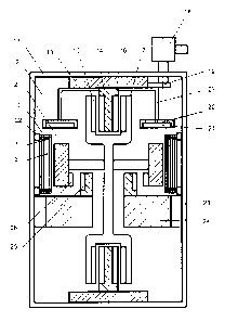
GA028752702014-12-01
representation in Figure 4. This Figure 4 shows the flywheel
mass 2, which rotates about the shaft 17 and is disposed in a
vacuum container 11, in which a vacuum 12 is situated. The
shaft 17 has a rotor unit 15 of the bearing on both sides,
whereby the bearing has superconducting elements 16 in an edging
14, on both sides, which edging represents a cooling mantle of
the superconducting bearing and is cooled by means of a
cryocooler 18, which is situated outside of the vacuum container
11. The cold is brought from the cryocooler 18 to the bearing
by means of a cooling connection 19 in the cryocooler 18 of the
edging of the bearing 14, whereby suspensions 13 are disposed on
both sides between the vacuum container 11 and the edgings 14 of
the cooling mantle. The safety container consists of the
lamellae 3, fixation elements 1, and cover rings 10, and
surrounds the flywheel mass 2 in protective manner, for which
purpose the safety container is attached to the vacuum container
11 by way of a holding structure 22. In advantageous manner,
this attachment between safety container and vacuum container 11
is structured in such a manner that the safety container can
rotate along in the holding structure, so that the energy of
parts that are accelerated away from the flywheel mass 2 can be
absorbed more quickly, without the safety container being
destroyed.
As an essential part of the flywheel storage unit, the
electrical machine 24 with its holding structure 23 is provided,
whereby the holding structure 23 connects the electrical machine
24 with the vacuum container 11. The rotor unit 26 of the
electrical machine 24 and the stator unit 25 are situated
disposed opposite the electrical machine 24 on the shaft 17.
12
CA 02875270 2014-12-01
In particularly advantageous manner, a cold surface 21 is
disposed on the edging 14 and the cooling mantle of the
superconducting bearing, on which surface gas particles in the
vacuum freeze and thereby increase or stabilize the vacuum. The
cold surface 21 has an insulation 20 on its back side. In this
way, the cold surface is prevented from losing energy in this
direction.
Figure 5 shows the solution according to the invention as a
flywheel storage unit that is structured as a rotor unit having
an outer rotor with cryocooler 18. The entire apparatus is
situated in a vacuum container, whereby on a shaft 17 that
surrounds the edging 14 of the cooling mantle with the
superconducting elements of the bearing 16 at its ends and has
the rotor unit 15 of the bearing in this region. The edging of
the cooling mantle 14 is connected with the vacuum container, by
way of the suspension 13, on both sides. The cryocooler 18 is
situated outside of the housing and has a cooling connection 19
to the bearing. The flywheel mass 2 is surrounded by a safety
container in the present case, too, which container consists of
lamellae 3, fixation elements 1, and cover rings 10, and is
connected with the vacuum container 11 by way of the holding
structure 22. In the present exemplary embodiment, as well,
cooling surfaces 21 having an insulation 20 are provided, in
advantageous manner, whereby the cooling surfaces 21 are
provided with a cooling connection 27 for the edging 14 for the
cooling mantle. A rotor unit 26 is disposed on the flywheel
mass 2, which unit lies opposite the stator unit 25 of the
electrical machine 24. The electrical machine 24 is connected
with the vacuum container 11 by means of a holding structure 23.
13
CA 02875270 2014-12-01
A further advantageous embodiment variant is shown in a
schematic representation by Figure 6, in which a flywheel
storage unit with flywheel mass 2 is shown, and the rotor unit
is structured as an external rotor. Cryo-container 18, cold
surface 21 and its insulation 20, as well as cooling connection
27 are structured in analogous manner to Figure 5. The same
holds true for the safety container around the flywheel mass,
whereby the flywheel mass 2 has a rotor unit 26 on both sides,
opposite which stator units 25 of the electrical machine 24 are
disposed, whereby the electrical machine 24 is disposed on both
sides of the safety container and are connected with the vacuum
container 11 by way of the holding structure 23.
In a further exemplary embodiment, which is shown in Figure 7,
the solution of the flywheel storage unit according to the
invention is shown without a safety container, whereby the
cooling surfaces 21 are provided with an insulation 20, serves
as cooling of the chamber 28 for liquid nitrogen 29, in other
words it is not a cryocooler but rather a cryogenic agent that
ensures cooling of the cold surface 21. The rotor unit 26 is
structured as an internal rotor, in other words rotor units 26
are disposed opposite the stator units 25 of the electrical
machine 24 on the shaft 17, which is connect with the vacuum
container 11 by way of the holding structure 23. The
superconducting elements 16 lie opposite the rotor unit 15 of
the bearing on both sides and shaft 17 on both sides, whereby in
this case, too, the edging 14 of the superconducting bearing are
connected with the vacuum container 11 by way of the suspension
13.
14
CA 02875270 2014-12-01
List of reference symbols used
1 fixation element with recesses
2 flywheel mass
3 lamella
4 hole for connecting rod
recess for insertion into holding structure
6 connecting joint between elements
7 element
8 cavity or fill volume of the element
9 connecting rod of the safety container
cover ring
11 vacuum container
12 vacuum
13 suspension of the superconducting bearing
14 edging and cooling mantle of the superconducting bearing
rotor unit of the bearing
16 superconducting elements of the bearing
17 shaft
18 cryocooler
19 cooling connection of the bearing
insulation of the cold surface
21 cold surface
22 holding structure of the safety container
23 holding structure of the electrical machine
24 electrical machine
stator unit of the electrical machine
26 rotor unit of the electrical machine
27 cooling connection of the cold surface
28 chamber for liquid nitrogen
29 liquid nitrogen
insulating suspension of the chamber