Note : Les descriptions sont présentées dans la langue officielle dans laquelle elles ont été soumises.
CA 02876037 2014-12-08
WO 2014/016108
PCT/EP2013/064443
- 1 -
Spring core having a fully active spring and method of manufacturing the same
FIELD OF THE INVENTION
The invention relates to a method of manufacturing a spring core, to a spring
core
having a fully active spring and to a fully active spring for use in spring
cores. The
invention relates in particular to pocket spring cores having a plurality of
springs re-
spectively enclosed in a pocket of fabric.
BACKGROUND
Spring cores are widely used in seating or bedding products. Such spring cores
com-
monly are made from a matrix of multiple springs joined together directly as
by helical
lacing wires, or indirectly as by fabric within which each individual spring
is contained.
Pocket spring cores in which springs are respectively contained in a pocket of
fabric
are popular, due to the comfort and luxury feel provided by pocket spring
cores.
In order to provide firm support, it is desirable to use springs having a high
firmness.
This can be attained by preloading springs. US 6 186 483 B1 and US 5 924 681
B1
respectively describe springs having knotted end turns, in which the spring is
pre-
loaded using a loop of fabric.
US 4 817 924 describes a spring core for a mattress in which springs have
unknotted
end turns. The end turns include portions which essentially extend
perpendicular to a
longitudinal axis of the spring. Other examples for coil springs having
unknotted end
turns are described in US 2010/0295223 Al and US 7 921 561 Bl, for example.
The
flat surface defined by the end turns of the springs, even in the rest state
of the
springs in which the springs are unloaded, assists in providing a flat support
surface,
which is desirable in terms of comfort.
Springs for use in pocket spring cores have traditionally been designed so as
to de-
fine an end surface oriented normal to the spring axis in the rest state of
the spring.
Frequently, the end turns are knotted. By using springs having end turns with
ring-
like portions oriented perpendicular to the longitudinal axis of the spring,
flat surfaces
may be defined at the upper and lower ends of the spring. Such ring-like
support sur-
CA 02876037 2014-12-08
WO 2014/016108
PCT/EP2013/064443
- 2 -
faces assist in providing the pocket spring core with comparatively flat upper
and
lower surfaces. Further, problems associated with wear of the pocket material
may
be mitigated.
While high comfort and luxury feel can be attained by using springs that have
flat end
turns oriented normal to the spring axis, the flat end turns do not contribute
to the
firmness of the spring. Thus, such spring configurations may require a greater
amount of wire. To provide greater firmness while reducing the overall wire
length, a
more aggressive pitch could be used on the central portion of the spring.
However, in
order for the spring to retain its shape memory, there are bounds for the
pitch which
can be used. The greater amount of wire required for producing the springs
used in
conventional pocket spring cores increases the costs of such spring cores.
SUMMARY
There is a continued need in the art for a spring core and method of
manufacturing
the same and for a spring which address some of the above needs. In
particular,
there is a continued need for such products and methods which allow
manufacturing
costs associated with pocket spring cores to be kept more moderate. There is a
need
for such products and methods in which a smaller amount of wire is required to
form
the springs which are inserted into the pockets, while providing a firmness
which is at
least comparable to that of conventional pocket springs.
According to an embodiment, a method of manufacturing a pocket spring core for
a
bedding or seating cushion is provided. A plurality of springs is provided.
Each spring
of the plurality of springs is enclosed in respectively an associated pocket
to form a
string of pocket springs. The plurality of springs comprises fully active
springs. Each
fully active spring respectively has a central spiral portion with at least
one turn, an
unknotted first end turn, and an unknotted second end turn, the first end turn
defining
a first end of the fully active spring and the second end turn defining an
opposing
second end of the fully active spring. The central spiral portion defines a
spring axis.
Each fully active spring is configured such that, in an uncompressed state and
when
the fully active spring is not enclosed in the associated pocket, the first
end turn and
the second end turn have a finite, i.e. non-zero, pitch angle, so that the
first end turn
and the second end turn contribute to a spring force of the fully active
spring.
CA 02876037 2014-12-08
WO 2014/016108
PCT/EP2013/064443
- 3 -
In the method, at least some of the springs used to form a pocket spring core
are
fully active springs. In the fully active springs, the end turns which define
opposing
axial ends of the fully active spring are provided with a finite, i.e. non-
zero, pitch an-
gle. The rest shape of each fully active spring is such that the end turns of
the fully
active springs do not define flat rings extending in a plane perpendicular to
the spring
axis, but contribute to the spring force. This allows the amount of wire
required to
attain a given firmness to be reduced.
The rest shape of each fully active spring may be such that, in the
uncompressed
state of the fully active spring and when the fully active spring is not
enclosed in the
associated pocket, the fully active spring has a finite pitch angle throughout
the first
end turn and throughout the second end turn.
The rest shape of each fully active spring may be such that, in the
uncompressed
state of the fully active spring and when the fully active spring is not
enclosed in the
associated pocket, the first end turn has a pitch angle of at least 8 at any
location on
the first end turn within 35 mm from an upper spring end. Alternatively or
additionally,
the rest shape of each fully active spring may be such that, in the
uncompressed
state of the fully active spring and when the fully active spring is not
enclosed in the
associated pocket, the second end turn has a pitch angle of at least 8 at any
loca-
tion on the second end turn within 35 mm from a lower spring end. The upper
and
lower spring ends may be taken to be the outermost points of the spring in its
rest
shape along the direction defined by the spring axis. The distance of 35 mm
may be
measured along the spring wire.
Each fully active spring and the associated pocket may be dimensioned such
that,
when the fully active spring is enclosed in the associated pocket, the first
and second
end turns are compressed such that the compressed first end turn lies in a
first plane
arranged at an angle different from 90 relative to the spring axis and the
com-
pressed second end turn lies in a second plane arranged at an angle different
from
90 relative to the spring axis.
Each fully active spring may further include a first end extension which
extends from
the first end turn and bends toward the central spiral portion. Each fully
active spring
may further include a second end extension which extends from the second end
turn
and bends toward the central spiral portion. Problems associated with wear of
the
pocket material may thereby be mitigated. The first end extension and the
second
CA 02876037 2014-12-08
WO 2014/016108
PCT/EP2013/064443
- 4 -
end extension may respectively have a length of 10 to 20 mm, measured along
the
wire of the end extensions.
The central spiral portion of each fully active spring may comprise at least
one turn.
The central spiral portion of each fully active spring may comprise at least
two turns.
Each fully active spring may have at least four turns, including the first and
second
end turns.
Each fully active spring may have a wire gauge selected from an interval from
at
least 0.8 mm to at most 2.2 mm. Each fully active spring may have a wire gauge
se-
lected from an interval from at least 1.6 mm to at most 2.2 mm.
The central spiral portion of each fully active spring may have a diameter
selected
from an interval from at least 25 mm to at most 90 mm. The central spiral
portion of
each fully active spring may have a diameter selected from an interval from at
least
60 mm to at most 80 mm.
The method may comprise performing an ultrasonic welding operation to form
longi-
tudinal and transverse seems of the pockets.
The method may comprise attaching plural strings of pocket springs to each
other to
form a pocket spring core.
The method may be such that each spring used in the pocket spring core is a
fully
active spring.
The fabric from which the pockets are formed may be a nonwoven fabric.
The method may comprise compressing the springs of the pocket spring core in a
direction parallel to the spring axis to compress the pocket spring core, and
winding
up the compressed pocket spring core about an axis which is transverse to the
spring
axes of all pocketed springs. The pocket spring core may thereby be brought
into a
roll-shape with compact dimensions, which is particularly suitable for
shipping.
The method may comprise forming the fully active springs using a coiler. The
method
may comprise heat-treating the fully active springs prior to inserting them
into the
associated pockets of fabric.
CA 02876037 2014-12-08
WO 2014/016108
PCT/EP2013/064443
- 5 -
According to another embodiment, a pocket spring core for a bedding or seating
cushion is provided. The pocket spring core comprises an array of pocket
springs,
the array of pocket springs comprising fully active springs respectively
enclosed in an
associated pocket of fabric. Each fully active spring respectively has a
central spiral
portion with at least one turn and defining a spring axis, an unknotted first
end turn
defining a first end of the fully active spring, and an unknotted second end
turn defin-
ing an opposing second end of the fully active spring. Each fully active
spring has a
rest shape in which the first end turn and the second end turn have a finite,
i.e. non-
zero, pitch angle, so that the first end turn and the second end turn
contribute to a
spring force of the fully active spring.
The rest shape of each fully active spring may be such that the first end turn
has a
pitch angle of at least 8 at any location on the first end turn within 35 mm
from an
upper spring end. The rest shape of each fully active spring may be such the
second
end turn has a pitch angle of at least 8 at any location on the second end
turn within
35 mm from a lower spring end.
Each fully active spring and the associated pocket may be dimensioned such
that,
when the fully active spring is enclosed in its associated pocket, the first
end turn is
compressed such that the compressed first end turn lies in a first plane
arranged at
an angle different from 90 relative to the spring axis. Each fully active
spring and t
associated pocket may be dimensioned such that, when the fully active spring
is en-
closed in its associated pocket, the second end turn is compressed such that
the
compressed second end turn lies in a second plane at an angle different from
90
relative to the spring axis.
Each fully active spring may further include a first end extension which
extends from
the first end turn and bends toward the central spiral portion. Each fully
active spring
may further include a second end extension which extends from the second end
turn
and bends toward the central spiral portion. Problems associated with wear of
the
pocket material may thereby be mitigated.
The central spiral portion of each fully active spring may comprise at least
one turn.
The central spiral portion of each fully active spring may comprise at least
two turns.
Each fully active spring may have at least four turns, including the first and
second
end turns.
CA 02876037 2014-12-08
WO 2014/016108
PCT/EP2013/064443
- 6 -
Each fully active spring may have a wire gauge selected from an interval from
at
least 0.8 mm to at most 2.2 mm. Each fully active spring may have a wire gauge
se-
lected from an interval from at least 1.6 mm to at most 2.2 mm.
The central spiral portion of each fully active spring may have a diameter
selected
from an interval from at least 25 mm to at most 90 mm. The central spiral
portion of
each fully active spring may have a diameter selected from an interval from at
least
60 mm to at most 80 mm.
The pockets may be formed from a nonwoven fabric.
According to another embodiment, a fully active spring for a pocket spring
core for a
bedding or seating cushion is provided. The fully active spring has a central
spiral
portion with at least one turn, an unknotted first end turn defining a first
end of the
fully active spring, and an unknotted second end turn defining a second end of
the
fully active spring arranged opposite to the first end. The fully active
spring has a rest
shape in which the first end turn and the second end turn have a finite, i.e.
non-zero,
pitch angle, so that the first end turn and the second end turn contribute to
a spring
force of the fully active spring.
The rest shape of the fully active spring may be such that the first end turn
has a
pitch angle of at least 8 at any location on the first end turn within 35 mm
from an
upper spring end. The rest shape of the fully active spring may be such the
second
end turn has a pitch angle of at least 8 at any location on the second end
turn within
mm from a lower spring end.
The fully active spring may further include a first end extension which
extends from
the first end turn and bends toward the central spiral portion. The fully
active spring
30 may further include a second end extension which extends from the second
end turn
and bends toward the central spiral portion. Problems associated with wear of
the
pocket material may thereby be mitigated.
The central spiral portion of the fully active spring may comprise at least
one turn.
35 The central spiral portion of the fully active spring may comprise at
least two turns.
The fully active spring may have at least four turns, including the first and
second end
turns.
CA 02876037 2014-12-08
WO 2014/016108
PCT/EP2013/064443
- 7 -
The fully active spring may have a wire gauge selected from an interval from
at least
0.8 mm to at most 2.2 mm. The fully active spring may have a wire gauge
selected
from an interval from at least 1.6 mm to at most 2.2 mm.
The central spiral portion of the fully active spring may have a diameter
selected from
an interval from at least 25 mm to at most 90 mm. The central spiral portion
of the
fully active spring may have a diameter selected from an interval from at
least 60 mm
to at most 80 mm.
Modifications and additional features of the pocket spring core and of the
fully active
spring according to embodiments correspond to modifications and additional
features
set forth in the context of the method of forming the pocket spring core.
According to embodiments, a pocket spring core is formed which includes fully
active
springs, in which first and second end turns at opposing ends of the spring
are not
configured as a flat ring extending normal to the spring axis, but have a
finite tilt an-
gle. The first and second end turns contribute to the spring force. The amount
of wire
required to provide adequate spring force may be reduced.
BRIEF DESCRIPTION OF THE DRAWINGS
Embodiments of the invention will be described with reference to the
accompanying
drawings.
FIG. 1 is a perspective view, partially broken away, of a cushion including a
pocket
spring core of an embodiment.
FIG. 2 shows a fully active spring which may be used in methods and pocket
spring
cores of an embodiment, before the spring is enclosed in an associated pocket.
FIG. 3 is a detail view of a portion of an end turn of the fully active spring
of FIG. 2.
FIG. 4 shows a rest shape of the fully active spring of FIG. 2 and a preloaded
state in
which the fully active spring is enclosed in its associated pocket.
CA 02876037 2014-12-08
WO 2014/016108
PCT/EP2013/064443
- 8 -
FIG. 5 is a detail view of a portion of an end turn of the fully active spring
of FIG. 2 in
the preloaded state in which the fully active spring is enclosed in its
associated
pocket.
FIG. 6 is a firmness graph showing the firmness of the fully active spring of
FIG. 2 in
comparison with conventional pocket springs.
FIG. 7 shows perspective views of a fully active spring which may be used in
meth-
ods and pocket spring cores of other embodiments, together with a perspective
view
of a conventional spring.
FIG. 8 shows perspective views of a fully active spring which may be used in
meth-
ods and pocket spring cores of yet other embodiments, together with a
perspective
view of a conventional spring.
DETAILED DESCRIPTION OF EMBODIMENTS
Exemplary embodiments of the invention will be described with reference to the
drawings. While some embodiments will be described in the context of specific
fields
of application, such as in the context mattresses, the embodiments are not
limited to
this field of application. The features of the various embodiments may be
combined
with each other unless specifically stated otherwise. Throughout the following
de-
scription, same or like reference numerals refer to same or like components or
mechanisms.
FIG. 1 shows a cushion in the form of a single-sided mattress 1 incorporating
a
pocket spring core 2 according to an embodiment. This cushion or mattress 1
com-
prises the pocket spring core 2 over the top of which there is a foam pad 4
covered
by a fiber pad 5. This complete assembly is mounted upon a base 7 and is com-
pletely enclosed within an upholstered covering material 6. While one
embodiment of
the invention described herein is illustrated and described as being embodied
in a
single-sided mattress, it is equally applicable to double-sided mattresses or
seating
cushions. In the event that it is utilized in connection with a double-sided
mattress,
the bottom side of the spring core may have a foam pad applied over the bottom
side
of the spring core and that pad is in turn covered by a fiber pad of
cushioning mate-
rial.
CA 02876037 2014-12-08
WO 2014/016108
PCT/EP2013/064443
- 9 -
The pocket spring core 2 is manufactured from multiple strings 3 of pocket
springs. A
string 3 of pocket springs may respectively be formed by providing a fabric
layer, in-
serting a fully active spring into the fabric layer, folding the fabric layer
so as to cover
the fully active spring either before or after insertion of the fully active
spring, and ap-
plying longitudinal and transverse seams, e.g. by welding. Each string 3 of
pocket
springs may extend across the full width of the product 1. These strings are
con-
nected in side-by-side relationship as, for example, by gluing the sides of
the strings
3 together in an assembly machine, so as to create an assembly or matrix of
springs
having multiple rows and columns of pocketed springs bound together as by
gluing,
welding or any other conventional assembly process commonly used to create
pocket spring cores. The pocket spring core 2 may be made upon any
conventional
pocket spring manufacturing machine and by any conventional pocketing spring
process, as long as at least some of the springs enclosed in an associated
pocket
are fully active springs, as will be explained in more detail hereinafter.
At least some of the springs enclosed in pockets of the pocket spring core 2
are fully
active springs. Generally, a fully active spring is defined to be a spring
which has a
rest shape in which first and second end turns defining opposite axial ends of
the
fully active spring respectively have a finite, i.e. non-zero, pitch angle, so
as to con-
tribute to the spring force of the fully active spring upon compression. The
first end
turn of the fully active spring does not have a portion which extends
perpendicularly
to the spring axis throughout a significant fraction of a turn. Similarly, the
second end
turn of the fully active spring does not have a portion which extends
perpendicularly
to the spring axis throughout a significant fraction of a turn. On each one of
the first
and second end turns, the spring may have a pitch angle greater than a
threshold,
e.g. greater than 5 or 8 , throughout a length which extends from an axially
outer-
most point of the spring towards a central portion of the spring.
With reference to FIG. 2 to 8, features of fully active springs according to
embodi-
ments will be described. The fully active springs have shape memory. This may
be
attained by suitable choice of material and suitable treatment of the springs,
e.g. by
heat-treatment. Geometrical features of the rest shape of the fully active
springs de-
scribed herein are therefore the same irrespective of whether the spring is in
an
unloaded state before it is inserted into the respective pocket or whether it
is in an
unloaded state after it is removed again from its associated pocket. Due to
the shape
memory, geometrical features of the rest shape of the fully active springs
define the
fully active springs even when the fully active springs are deformed to have a
differ-
CA 02876037 2014-12-08
WO 2014/016108
PCT/EP2013/064443
- 10 -
ent configuration, e.g. while they are arranged in and preloaded by an
associated
pocket of fabric.
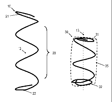
FIG. 2 shows a fully active spring 10 which may be used in at least some or in
all
pockets of the pocket spring core. FIG. 2 shows the fully active spring 10 in
an
unloaded state in which it is not inserted into and not enclosed by the
associated
pocket of fabric.
The fully active spring 10 has unknotted end turns. There are free wire ends
25, 26
which remain unknotted, even when the fully active spring 10 is inserted into
the as-
sociated pocket of fabric. The end turns of the fully active spring 10 are
tilted relative
to a spring axis 13. The rest shape of the fully active spring 10 is such that
the end
turns do not have larger portions that extend in a plane perpendicular to the
spring
axis 13, as is the case for conventional springs for pocket spring cores. When
used in
a pocket spring core, the fully active spring is preloaded and kept in the
preloaded
position by the pocket in which the fully active spring is enclosed, as will
be described
more fully hereinafter.
Generally, the fully active spring 10 has a central spiral portion 20, a first
end turn 21
and a second end turn 22. The central spiral portion 20 has at least one turn
and may
have at least two turns. Overall, the fully active spring 10 may have about
four turns,
for example, including the end turns 21, 22. The first end turn 21 and the
second end
turn 22 are provided on opposite sides of the central spiral portion 20 and
define op-
posite ends of the fully active spring 10. A first end extension 23 may extend
from the
first end turn 21 and may bend back towards the central spiral portion 20. The
first
end extension 23 may extend from a upper axial end 11 of the fully active
spring 10,
which is an outermost point of the fully active spring 10 in a direction along
the spring
axis 13. A second end extension 24 may extend from the second end turn 22 and
may bend back towards the central spiral portion 20. The second end extension
24
may extend from a lower axial end 12 of the fully active spring 10, which is
the other
outermost point of the fully active spring 10 in the direction along the
spring axis 13.
The first end turn 21 and the second end turn 22 of the fully active spring 10
are tilted
relative to the spring axis 13. As will be explained in more detail below, the
end turns
21, 22 of the fully active spring are compressed when the fully active spring
10 is en-
closed in its associated pocket of fabric. The first end turn 21 and the
second end
turn 22 contribute to the spring force of the fully active spring 10, due to
the inclina-
CA 02876037 2014-12-08
WO 2014/016108
PCT/EP2013/064443
- 1 1 -
tion of the first end turn 21 and the inclination of the second end turn 22.
The first end
turn 21 and the second end turn 22 and the associated first and second end
exten-
sions 23, 24 may, but do not need to have a shape in which they essentially
extend
in planes that are arranged at an angle different from 90 relative to the
spring axis
13 when the fully active spring 10 is in an unloaded state, i.e. when the
fully active
spring 10 has its rest shape.
The first end turn 21 and the second end turn 22 of the fully active spring 10
may be
arranged such that, in a side view as shown in FIG. 2, the first and second
end turns
21, 22 are not parallel to each other, but have tangent planes which converge
to-
wards each other. In a side view as shown in FIG. 2, one of the first and
second end
turns 21, 22 may be inclined downward and the other one of the first and
second end
turns 21, 22 may be inclined upward.
The fully active spring 10 may have a wire gauge greater than or equal to 0.8
mm
and less than or equal to 2.2 mm. The fully active spring 10 may optionally
have a
wire gauge which greater than or equal to 1.6 mm and less than or equal to 2.2
mm.
Each turn of the central spiral portion 20 of the fully active spring 10 may
have a di-
ameter which is at least 25 mm and at most 90 mm. Each turn of the central
spiral
portion 20 of the fully active spring 10 may optionally have a diameter which
is at
least 60 mm and at most 80 mm.
On each of the first and second end turns 21, 22, the spring may have a finite
pitch
angle throughout at least a certain length. For illustration, on each of the
first and
second end turns 21, 22, the pitch angle may be at least 8 for a pre-defined
length
along the spring from the respective upper and lower spring ends 11, 12
towards the
central spring portion 20.
The first end turn 21 may have a pitch angle of at least 8 at any location on
the first
end turn within 35 mm, measured along the spring wire, from the upper spring
end 11
towards the central spring portion 20. The second end turn 22 may have a pitch
an-
gle of at least 8 at any location on the second end turn within 35 mm,
measured
along the spring wire, from the lower spring end 12 towards the central spring
portion
20.
CA 02876037 2014-12-08
WO 2014/016108
PCT/EP2013/064443
- 12 -
In other embodiments, the first end turn 21 may have a pitch angle of at least
5 at
any location on the first end turn within a pre-defined distance, measured
along the
spring wire, from the upper spring end 11 towards the central spring portion
20. The
second end turn 22 may have a pitch angle of at least 5 at any location on
the sec-
ond end turn within a pre-defined distance, measured along the spring wire,
from the
lower spring end 12 towards the central spring portion 20.
The first end extension 23 and the second end extension 25 may respectively
have a
length of 10 to 20 mm, measured along the wire of the end extension 23 and 25,
re-
spectively.
FIG. 3 shows a detail view of an end turn 21 of the fully active spring for
further illus-
tration of the inclined configuration of the end turn. A tangent 15 may be
defined for
any point on the end turn 21 which is located within a pre-defined distance
from the
upper spring end 11. The tangent 15 intersects a plane 14 which is
perpendicular to
the spring axis 13. The tangent 15 is oriented at an angle 16 relative to the
plane 14.
The angle 16 may define a pitch angle of the end turn 21 at the respective
point on
the end turn 21. The angle 16 may be at least 8 at any location on the first
end turn
21 within 35 mm, measured along the spring wire, from the upper spring end 11
to-
wards the central spring portion 20.
A spring having the configuration described with reference to FIG. 2 and 3 has
been
found to provide good support and firmness. The spring of an embodiment
reduces
the amount of wire compared to conventional pocket springs which, when in an
unloaded condition, have end turns with horizontal sections that do not
contribute to
the spring force.
Each fully active spring 10 used in the pocket spring core 1 and its
associated pocket
may be dimensioned such that the end turns of the fully active spring 10 are
com-
pressed by the pocket of fabric when the fully active spring is enclosed in
the associ-
ated pocket. The first end turn 21 and the second end turn 22 may be
compressed
flat by the pocket material. The first end turn 21 and the second end turn 22
may be
compressed by the pocket such that, in the state in which the fully active
spring is
enclosed in its associated pocket, at least a portion of the compressed first
end turn
defines an upper end of the pocketed fully active spring and the compressed
first end
turn defines a first plane which is arranged at an angle different from 90 to
the spring
axis 13. Similarly, the second end turn 22 may be compressed such that, in the
state
CA 02876037 2014-12-08
WO 2014/016108
PCT/EP2013/064443
- 13 -
in which the fully active spring is enclosed in its associated pocket, at
least a portion
of the compressed second end turn defines a lower end of the pocketed fully
active
spring and the compressed second end turn defines a second plane which is ar-
ranged at an angle different from 90 to the spring axis 13. The first and
second
planes may be angled relative to each other.
FIG. 4 illustrates the compression of the first and second end turns 21, 22
when the
fully active spring 10 is enclosed in its associated pocket 35 of fabric. The
pocketed
fully active spring 30 has an axial length which is smaller than that of the
rest shape
of the fully active spring 10. The shape memory of the fully active spring
ensures that
the pocketed fully active spring 30 would resume its rest shape illustrated on
the left-
hand side of FIG. 4 when removed from the pocket 35.
When the fully active spring is enclosed in its associated pocket 35, the
first end turn
21 is compressed by the pocket 35 to form a compressed first end turn 31 of
the
pocketed fully active spring 30. The second end turn 22 is compressed by the
pocket
35 to form a compressed second end turn 32 of the pocketed fully active spring
30.
The compressed first end turn 31 and the compressed second end turn 32 may be
essentially flat, while not necessarily arranged perpendicularly to the spring
axis 13.
The first end extension 31 and the second end extension 32 may be arranged so
as
to be offset from the compressed first end turn 31 and the compressed second
end
turn 32. The first end extension 31 and the second end extension 32 may be ar-
ranged so as to be located in the space defined between the compressed first
end
turn 31 and the compressed second end turn 32. This allows problems associated
with wear of the pocket material to be mitigated.
FIG. 5 illustrates a detail view of the compressed first end turn 31 of a
fully active
spring when the fully active spring is enclosed in its associated pocket. The
com-
pressed first end turn 31 defines an upper end of the pocketed fully active
spring.
The compressed first end turn 31 defines a first plane 36 which is arranged at
an an-
gle different from 90 to the spring axis 13. I.e., a normal 37 to the first
plane 36 is
oriented at an angle 38 greater than zero relative to the spring axis 13. The
angle 38
may be made small to reduce bumpiness of the upper surface of the spring core.
While a configuration in which the compressed first and second end turns 31,
33 are
not oriented completely horizontally when the pocket spring core is installed
in a
product may give rise to a small degree of bumpiness in the upper and lower
sur-
CA 02876037 2014-12-08
WO 2014/016108
PCT/EP2013/064443
- 14 -
faces of the pocket spring core, such bumpiness may at least partially be
compen-
sated by suitable padding material. The tilted configuration of the first and
second
planes defined by the compressed first and second end turns, respectively, may
be
acceptable in view of the overall reduction in wire material needed when fully
active
springs of embodiments are used.
The finite pitch angle of the first end turn and the finite pitch angle of the
second end
turn have the effect that the end turns contribute to the spring force. The
end exten-
sions 23, 25 do generally not contribute to the spring force, which is
acceptable due
to their small length.
FIG. 6 illustrates the firmness for a pocketed fully active spring at curve 41
compared
to conventional commercial springs having horizontal end turns at curves 42,
43.
FIG. 6 shows the deflection-force curves for these springs. The curve 41 has
been
obtained for a fully active spring which has a rest shape, before being
inserted into
an associated pocket, in which the opposite first and second end turns have a
finite
pitch angle. The other curves 42, 43 have been obtained for springs in which
the
spring turns end in a flat, horizontal way. Curve 43 shows a normal spring
without
increased pretension and curve 42 shows a spring having increased pretension.
While configurations of fully active springs which have a generally
cylindrical configu-
ration (fully active cylindrical coil springs) are illustrated in FIG. 2 to 5,
the concepts
described herein are equally applicable to a wide variety of other spring
configura-
tions, such as hourglass-shaped coil springs or barrel shaped coil springs. In
particu-
lar, the turns of the central portion of the fully active spring may have a
diameter
which varies as a function of position along the spring axis. The fully active
springs
may respectively have unknotted end turns which define opposite ends of the
fully
active spring. The opposite end turns may have a finite pitch angle, and may
not
have any sections which extend in a plane normal to the spring axis throughout
a
significant fraction of a turn.
FIG. 7 shows a fully active spring 50 which is configured as a fully active
hourglass-
shaped spring. FIG. 7 shows the fully active spring 50 in an unloaded state,
i.e. when
the fully active spring 50 has its rest shape. The fully active spring 50 has
a central
portion 53 which defines a spring axis 13. The diameter of the turns of the
central
portion varies and is minimum at the axial center of the fully active spring
50.
Thereby, an hourglass-shape is formed.
CA 02876037 2014-12-08
WO 2014/016108
PCT/EP2013/064443
- 15 -
A first end turn 51 which defines a first end of the fully active spring 50
and a second
end turn 52 which defines an opposite second end of the fully active spring 50
have a
finite pitch angle.
For further illustration of the design of end turns 51, 52 having a finite
pitch angle, a
conventional hourglass spring 70 having unknotted end turns 71, 72 is shown
for
comparison. The conventional spring 70 has end turns 71, 72 which define the
op-
posing ends of the conventional spring 70. However, the end turns 71, 72
define
rings which are located in planes that extend perpendicular to the spring
axis. The
end turns 71, 72 do not contribute to the spring force of the spring 70.
FIG. 8 shows a fully active spring 60 which is configured as a fully active
cylindrical
spring. FIG. 8 shows the fully active spring 60 in an unloaded state, i.e.
when the fully
active spring 60 has its rest shape. The fully active spring 60 has a central
portion 63
which defines a spring axis 13. The diameter of the turns of the central
portion is
constant, thereby forming a cylindrical spring.
A first end turn 61 which defines a first end of the fully active spring 60
and a second
end turn 62 which defines an opposite second end of the fully active spring 60
have a
finite pitch angle.
For further illustration of the design of end turns 61, 62 having a finite
pitch angle, a
conventional cylindrical spring 80 having unknotted end turns 81, 82 is shown
for
comparison. The conventional spring 80 has end turns 81, 82 which define the
op-
posing ends of the conventional spring 80. However, the end turns 81, 82
define
rings which are located in planes that extend perpendicular to the spring
axis. The
end turns 81, 82 do not contribute to the spring force of the spring 80, in
contrast to
the end turns 61, 62 of a fully active spring of an embodiment.
Other features, characteristics and modifications of the fully active springs
50 and 60
of FIG. 7 and 8 may be the same as any one of those explained with reference
to
FIG. 1 to 6. In particular, the wire gauge, the diameter of the turns, the
number of
turns and/or the pitch angle on the first and second end turns may have any
one of
the configurations explained with reference to FIG. 1 to 6.
CA 02876037 2014-12-08
WO 2014/016108
PCT/EP2013/064443
- 1 6 -
In the pocket spring core of any one of the embodiments described herein, the
fabric
from which the pockets are formed may be semi-impermeable. The fabric may be
configured such that it has a greater resistance to air flow directed from an
exterior to
an interior of the pocket than to air flow directed from an interior to an
exterior of the
pocket. The seams which delimit the respective pockets may be sinusoidal
welded
seams. These configurations may suitably used in connection with the high
firmness,
fully active springs of embodiments to provide high firmness when the pocket
spring
core is loaded.
When manufacturing a pocket spring core, the fully active springs may undergo
vari-
ous processing steps which enhance the shape memory and/or which make it
easier
to store and ship the pocket spring core. For illustration, the fully active
springs may
be subjected to heat treatment so as to enhance shape memory. For further
illustra-
tion, the pocket spring core may be compressed flat and may be wound to form a
roll-shaped pocket spring core, which may be convenient for storing and/or
shipping.
Fully active pocket springs, pocket spring cores including the same and
methods of
manufacturing such pocket spring cores have been described in detail. Other
con-
figurations may be implemented in other embodiments. For illustration, a wide
variety
of other configurations of fully active springs may be used, in which
unknotted first
and second end turns have a finite pitch angle. For illustration, barrel-
shaped springs
may be used in which turns of the central portion have a diameter varying
along the
spring axis, with the diameter being maximum at the axial center of the
spring.
For further illustration, all pocketed springs of a pocket spring core may be
fully active
springs having unknotted first and second end turns which are inclined so as
to con-
tribute to the spring force of the fully active spring. However, in other
implementa-
tions, a pocket spring core of an embodiment may include fully active springs
having
a configuration as described above in some of the pockets and may further
include
conventional springs arranged in other pockets of the pocket spring core.
While exemplary embodiments have been described in the context of pocket
spring
cores for mattresses, the fully active springs and pocket spring cores using
the fully
active springs are not limited to this particular field of application.
Rather, embodi-
ments of the invention may be advantageously employed for pocket spring cores
for
any kind of seating or bedding furniture.