Note : Les descriptions sont présentées dans la langue officielle dans laquelle elles ont été soumises.
CA 02876559 2014-12-12
APPARATUS FOR CALIBRATING A POWER MEASUREMENT SYSTEM FOR POWER
TRANSFORMERS
The present invention relates to an apparatus for
calibrating a power measurement system for power transformers.
Minimization of power dissipation is a very important
criterion when employing power transformers in a power supply
network. Power dissipation, which is reflected for instance in
no-load losses or load losses, is a design- and/or production-
dependent factor, and it is therefore checked by the routine and
type test for power transformers according to IEC Standard
60076-1 or IEEE Standard C57.12.90-1999. The amount of power
dissipation has a direct impact on costs for the energy provider,
and it is therefore monetarily penalized against the producer
when the power transformer is purchased. For this reason, the
power dissipation should be assessed as accurately as possible on
purchasing a power transformer. Every high-voltage testing
laboratory for power transformers therefore has a so-called power
measurement system that has to be calibrated in order to
determine the power dissipation of the power transformer and
measure it as accurately as possible by means of the power
measurement system. It is moreover required by IEC Standard
60060-2 that such a power measurement system be calibrated.
- 1 -
CA 02876559 2014-12-12
Such power measurement systems as known from prior art
have sub-components that include a current and voltage source, a
voltage transformer, a current transformer, a test object, namely
the power transformer, and an evaluation device. In order to
ensure that the values measured by the power measurement system are
adequately accurate, it is in particular necessary to calibrate the
current transformer, the voltage transformer, and the evaluation
device. In this context, it is common practice to perform a time-
and cost-consuming, component-specific, individual calibration on
the mentioned sub-components of the power measurement system, i.e.
on the current transformer, the voltage transformer, and the
evaluation device. For this purpose, the sub-components current
transformer, voltage transformer, and evaluation device, have to be
dismantled from the power measurement system and sent to the
respective manufacturers of the sub-components for being calibrated
by them. After the individual calibration has been performed on
the sub-components, the power measurement system can be completed,
i.e. reassembled, again. In a subsequent step, the overall
measurement uncertainty of the power measurement system is
mathematically deduced from the measurement uncertainties of the
individual sub-components calibrated by the manufacturer and is
inferred for the entire power measurement system.
For the individual calibration of the sub-components of
the power measurement system, prior art uses a so-called reference
measurement system. In a reference measurement system, the
electrical parameters to be determined or calibrated are
standardized to values that represent the reference values, and
which are known to the operator. In other words, the reference
- 2 -
CA 02876559 2014-12-12
measurement system serves as reference system with electrical
output values that are known to the operator, at defined input
values. FIG. 1 shows the circuit arrangement of a reference
measurement system as known from prior art for calibrating
sub-components of the voltage transformer. For this purpose, the
reference measurement system has a high-voltage transformer 1 as a
voltage source, which high-voltage transformer 1 is electrically
connected with a reference voltage transformer 2 by means of power
supply lines. The reference voltage transformer 2 is in turn
electrically connected with a reference evaluation device 4 by
means of a measuring cable 3. The high-voltage transformer 1
furthermore electrically supplies the actual calibration object,
namely a voltage transformer 5 and an evaluation device 7, which
calibration object is disposed at the high-voltage transformer 1 in
an arrangement that is electrically symmetrical to the reference
voltage transformer 2 and the reference evaluation device 4.
FIG. 2 shows the circuit arrangement of another reference
measurement system as known from prior art for calibrating a
current transformer. For this purpose, a high-current transformer
8 is provided as a current source, which high-current transformer 8
is electrically connected with a reference current transformer 9 by
means of a high-current circuit, which reference current
transformer 9 in turn is connected via a reference measurement
cable 10 to a reference evaluation device 11. In a symmetrical
arrangement therewith, the actual sub-components to be calibrated,
namely the current transformer 12, which is connected via a
measuring cable 13 with the evaluation device 14, are also
- 3 -
CA 02876559 2014-12-12
connected with the high-current circuit of the high-current
transformer 8.
In both reference measurement systems shown in FIG. 1 and
2, a nominal-actual value comparison is performed, where the
physical quantities, or their respective values, which are
determined by the reference measurement system, are compared
against those of the individual sub-components to be calibrated.
In the reference measurement system of FIG. 1 for instance the
values determined in the reference voltage transformer 2 and the
reference evaluation device 4 are thus compared against those of
the calibration object, i.e. the voltage transformer 5 and the
evaluation device 7 B including, in each case, their corresponding
measuring cables 3 and 6.
All in all, the structure of prior art reference
measurement systems for calibrating the individual sub-components
is thus very cumbersome. On the one hand, the calibration requires
using technologically different reference measurement systems, on
the other hand, current transformers and voltage transformers have
to be sent to the respective manufacturers as individual components
for being calibrated.
The object of the present invention is therefore to
specify an apparatus for calibrating a power measurement system for
power transformers, which apparatus makes it unnecessary to use
different reference measurement systems for calibrating the
sub-components of the power measurement system, i.e. current
transformer, voltage transformer, and evaluation device, and which
- 4 -
apparatus dispenses with sending the sub-components to the
manufacturer for being individually calibrated.
The general inventive idea consists in integrating the
two known prior art reference measurement systems for calibrating a
current transformer, a voltage transformer, and an evaluation
device, into one common apparatus according to the invention for
calibrating a power measurement system for power transformers,
which apparatus is moreover arranged on a container in such a
manner that the apparatus is constructed to be movable by means of
a trailer, onto which the container is loaded, for performing
on-site calibration of the power measurement system for power
transformers. According to the invention, the mobile container
thus comprises a completely pre-installed apparatus for calibrating
a power measurement system. The apparatus according to the
invention installed in the container thus enables calibrating the
entire power measurement system by way of system calibration that
makes it possible to examine or calibrate the calibrating accuracy
of the individual components, and also the influence of the supply
lines between the individual components as well as the evaluation
algorithm of the evaluation device. The calibration accuracy
achieved in this manner is higher than when calibrating the
individual components.
Moreover, the individual sub-components of the apparatus
according to the invention require no specific preparation when the
CAN_DMS: \134606102\2
¨ 5 ¨
Date Recue/Date Received 2020-08-11
CA 02876559 2014-12-12
power measurement system is calibrated; in order to be calibrated,
the power measurement system only needs to be connected with the
apparatus according to the invention. Thus, the sub-components of
the power measurement system that are to be calibrated, namely the
current transformer, the voltage transformer, and the evaluation
device, also only require one common apparatus according to the
invention in order to be calibrated. It is no longer necessary
that the current transformer and the voltage transformer are each
calibrated individually by the respective manufacturer as is
required in prior art; the current transformer and the voltage
transformer can rather be calibrated together, on-site, in one
single calibration process at the same time, using only one single
apparatus according to the invention. Until now, on-site
calibration by means of the separate prior art calibrating systems
was not economically feasible, as each calibrating system would
have had to be installed on a container and trailer of its own.
Two containers, including trailers and towing vehicles, would have
thus been necessary in order to be able to perform a calibration of
the sub-components. Only by integrating the two reference
measurement systems, which in prior art have so far been separate
systems, into one common apparatus according to the invention,
which is on one container, is on-site calibration of a power
measurement system rendered an economically profitable alternative
for a test field operator. Also, it has not been technically
possible up to now to simply install the separate calibrating
systems of a known prior art construction type onto one single,
common container, as it could not have been ensured for the
respective system components of the corresponding calibration
- 6 -
CA 02876559 2014-12-12
system to be spaced sufficiently apart at the necessary dielectric
distances. The apparatus according to the invention has now made
this possible for the first time.
It has also been shown that the apparatus according to
the invention ensures determining the power dissipation of the
power transformer with significantly higher accuracy than the prior
art because the hitherto used mathematical deduction of the
measurement uncertainty from the measurement uncertainties of the
sub-components is dispensed with. This is because it has been
recognized that in particular the measuring lines between the
current and voltage transformers and the corresponding evaluation
device as well as the evaluation algorithm in the evaluation device
itself, which evaluation algorithm determines the phase angle
between the measured electrical quantities and assesses the power
from the quantities current, voltage, and phase angle, have an
influence on the measuring result within the power measurement
system or the reference measurement system during the calibration
of the sub-components. The apparatus according to the invention
thus achieves significantly higher measurement accuracy in
comparison to the individual calibration of the sub-components of
the power measurement system by means of the known separate
reference measurement systems and the subsequent extrapolation of
the measuring error to the entire power measurement system.
Frequently, the measuring data of the sub-components were also
manually measured and consolidated for the entire power measurement
system, thus transferring the measuring error of the sub-components
into the calibration record of the entire power measurement system
- 7 -
CA 02876559 2014-12-12
that eventually negatively affects the accuracy of the measuring
values of the power measurement system.
In the following, the invention will be illustrated in
more detail by means of exemplary embodiments using the described
drawings, in which:
FIG. 1 shows the circuit diagram of a reference
measurement system according to the prior art for calibrating a
voltage transformer;
FIG. 2 shows the circuit diagram of a reference
measurement system according to the prior art for calibrating a
current transformer;
FIG. 3 shows the schematic circuit diagram of a first
exemplary embodiment of an apparatus according to the invention for
calibrating a power measurement system of a power transformer; and
FIG. 4 shows the schematic circuit diagram of a
further exemplary embodiment of an apparatus according to the
invention for calibrating a power measurement system of a power
transformer.
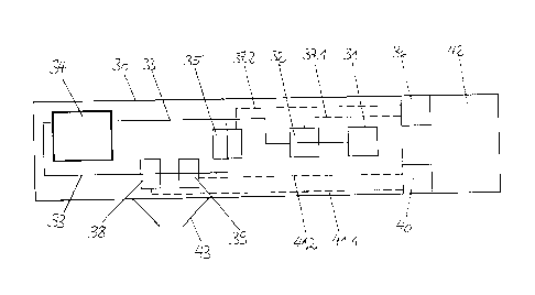
FIG. 3 shows the schematic circuit diagram of a first
exemplary embodiment of an apparatus according to the invention for
calibrating a power measurement system of a power transformer in a
top plan view of a container 30. The container 30 can be for
instance a customary 40-feet standard container that is compatible
with and movable by means of a trailer and towing vehicle. A
high-voltage transformer 31 arranged in the rear area of the
container 30 serves as voltage source, and it supplies the required
test voltage of up to 100 kV for the apparatus according to the
- 8 -
invention. A reference voltage transformer 32 is connected with
the high-voltage transformer 31 by means of an electric line. The
reference voltage transformer 32, which transforms an input voltage
to an output voltage that is known to the test field operator, is
in turn electrically connected both with a high-current circuit 33
having a high-current transformer 34, which supplies a maximum test
current of 2 kA, and with a reference current transformer 35 that
in turn transforms an input current to an output current that is
known to the test field operator. Furthermore, a reference
evaluation device 36 is electrically connected via reference
measuring cables 37.1 and 37.2 both with the reference voltage
transformer 32 and the reference current transformer 35,
respectively. The reference evaluation device 36, which is also
standardized to electrical parameters that are known to the
operator, records the signals from the reference current
transformer 32 and the reference voltage transformer 35 during the
power measurement and uses them to calculate the active power P,
the apparent power S, the frequency f, and the phase angle j
between applied current and applied voltage. In addition, it is
possible to evaluate the harmonic content of the sinusoidal
quantities by means of the reference evaluation device 36. A very
common reference evaluation device 36 for power measurement is
YOKOGAWArm WT3000. In the apparatus according to the invention, the
sub-components of the power measurement system that are to be
calibrated, namely a voltage transformer 38, a current transformer
39, and an evaluation device 40, are also looped into the
high-current circuit 33. Arranged likewise analogous symmetrically
with respect to the reference measuring devices, the evaluation
CAN_DMS: \134606102\2
¨ 9 ¨
Date Recue/Date Received 2020-08-11
1
CA 02876559 2014-12-12
device 40 is electrically connected via measuring cables 41.1 and
41.2 both with the voltage transformer 38 and the current
transformer 39, respectively. In order to ensure the measurement
accuracy of the apparatus according to the invention, the reference
evaluation device 36 and the evaluation device 40 to be calibrated
are in an electromagnetically shielded control room 42 in the
container 30. In the present context, the voltage transformer 38
and the current transformer 39 can be positioned in the container
30 in a particularly simple manner by means of a door 43, which is
preferably designed as a double-wing door, provided in the side
wall of the container 30. It has furthermore been shown that
placing all system components in the container 30 further improves
the measurement accuracy of the apparatus according to the
invention because all installed system components are subject to
the same climatic conditions due to the air-conditioning inside the
container 30.
In contrast to FIG. 3, the voltage transformer 38 and the
current transformer 39 in FIG. 4 can be positioned outside of the
container 30 by means of an extendable high-current connection 44.
The evaluation device 40, which is also arranged outside of the
container 30, is electrically connected with both the voltage
transformer 38 and the current transformer 39 via a measuring cable
41.1 and 41.2, respectively, in this embodiment, too.
Communication between the reference evaluation device 36 and the
evaluation device 40 to be calibrated here is performed by means of
a data connection line 45, for instance by way of a remote control
connection.
- 10 -
CA 02876559 2014-12-12
Current and voltage transformers that can be used in the
context of the present invention are known from the book
"Hochspannungstechnik (High-Voltage Technology)" by Andreas
Kuchler, Springer Verlag, 2005. In the prior art, capacitive
voltage transformers have proven particularly successful for
determining the voltage, whereas inductive current transformers are
suited for determining the current.
Such a capacitive voltage transformer as known from prior
art is always connected with a current-carrying conductor. More
precisely, two series-connected capacitors are connected with a
current-carrying conductor. The low-voltage capacitor in a lower
housing here is connected with the ground potential. A higher
voltage capacitor is in a separate, insulating support tube, and it
separates the high voltage potential at the upper housing from the
ground potential of the lower housing. The upper housing, which
surrounds the connection between the conductor and the higher
voltage capacitor, is also at high voltage potential. The voltage
at the current-carrying conductor can be determined from the ratio
of the two capacitors and the voltage measured at the low-voltage
capacitor.
Usually, the current is determined using inductive
current transformers. In this instance, a closed, annular iron
core with a winding wound around it is around the current-carrying
conductor, in which winding a current is induced as soon as the
conductor carries a current. A shunt resistor is series-connected
with the winding. The current of the conductor can be determined
by measuring the current at the shunt resistor. The housing of the
apparatus is designed in three parts. The upper housing encloses
- 11 -
CA 02876559 2014-12-12
the current-carrying conductor and is connected with the lower
housing via an insulating support tube. The upper housing is at
high voltage potential, whereas the lower housing is at ground
potential.
- 12 -
CA 02876559 2014-12-12
Reference Signs
High-voltage transformer
6 Reference voltage transformer
7 Reference measuring cable
8 Reference evaluation device
9 Voltage transformer
Measuring cable
11 Evaluation device
12 High-current transformer
13 Reference current transformer
14 Reference measuring cable
Reference evaluation device
16 Current transformer
17 Measuring cable
18 Evaluation device
19 Container
High-voltage transformer
21 Reference voltage transformer
22 High-current circuit
23 High-current transformer
24 Reference current transformer
Reference evaluation device
26.1 and 37.2 Reference measuring cables
27 Voltage transformer
28 Current transformer
29 Evaluation device
30.1 and 41.2 Measuring cables
- 13 -
CA 02876559 2014-12-12
31 Control room
32 Door
33 Extendable high-current connection
34 Data connection line
- 14 -