Note : Les descriptions sont présentées dans la langue officielle dans laquelle elles ont été soumises.
CA 02877860 2014-12-17
WO 2014/008571 PCT/CA2012/000641
1
LOW PROFILE SEED TREATER WITH METERING FUNCTIONALITY
Field of the Invention
The present invention relates to seed treatment apparatuses and methods, and
more particularly
to seed treatment apparatuses and methods that incorporate seed metering.
Background of the Invention
it is well known in the agricultural arts to apply various treatments to seeds
before planting, in an
effort. to reduce the amount. of such treatment that would otherwise be
required were it to be
applied to a field after planting. For example, treatments may include the
application of
fertilizers, insecticides, pesticides and fungicides, and normally take the
form of liquid chemical
that is sprayed onto the seed. While seed treatment apparatuses are
commercially available, it is
more common to see a farmer spray treatment directly onto seed just before it
is drawn up an
auger, the auger being employed to mix the treated seed in an effort to spread
the treatment
coating over as much seed surface as possible before planting. Such manual
application,
however, normally results in overuse of expensive treatment (due to a failure
to properly meter
the seed and control the treatment amount) and loss of treatment (particularly
due to wind) and -
may even have health implications depending on the nature and toxicity of the
particular
treatment being applied, although manual application may also result in too
little treatment being
applied and therefore a reduction in the desired effect.
Various seed treatment apparatuses have been disclosed in the prior art, some
of which have
been made commercially available. For example, Canadian Patent No. 518,715 to
Calkins
provides an early example of a seed treatment device that incorporates
metering of seed, where a
"dump pan" is employed, but the metering approach is unfortunately inaccurate
and the focus of
the teaching is on slurry agitation rather than achieving optimal treatment
application. Canadian
Patent Application No. 2,704,589 to Hunter et al. teaches a more accurate
metering system,
where seed weight is determined using a load cell to calculate an optimal
treatment application,
CA 02877860 2014-12-17
WO 2014/008571
PCT/CA2012/000641
2
but the apparatus is designed for batch processing in a research setting
rather than the high-
throughput seed treatment required in a commercial fanning Operation.
One of the commercially available seed treaters for on-farm use is described
in Canadian Patent
No. 2,196,001 to Graham. The Graham apparatus, or "03", is used with two
augers, where one
auger transports seed upwardly (from an auger hopper positioned under a hopper-
bottom bin or
similar) toward the upper intake of the seed treater, and the seed is then
sprayed with treatment
as it falls downwardly through the seed treater, with the second auger serving
to mix the treated
seed and transport it upwardly to a truck or storage unit. The seed falls in
an annular pattern
adjacent the inner surface of the treater, and a centrally-disposed nozzle
sprays treatment in a
conical spray pattern in an effort to contact as much seed as possible. While
this apparatus may
provide an improvement over manual application methods, it has been found that
treatment
builds up around the inner surface of the treater and is therefore wasted.
However, a more
significant issue has been noted with this and other auger-based treaters,
namely, that using an
auger to determine volume flow through the system (and hence the amount of
treatment to apply)
can be quite inaccurate due to product slippage inherent in the screw-type
transport mechanism.
Also, optimal treatment application rates are provided in m11100k.g, so a
reliance on volume
alone without an adjustment for seed density can contribute to an application
rate that is not
optimized, hence resulting in treatment waste. In a commercial farming
operation, the cost of
such waste can be substantial.
The problem of treatment waste and optimized application rates in a commercial
farming context
has not been canvassed to a significant extent in the prior art. One example
is United States
Patent Application No. 12/848,412 to Reineccius et al., which teaches an
apparatus that provides
an accurate means for measuring seed volume to determine an optimal treatment
application rate.
However, the apparatus itself is of a physical scale that may limit its on-
farm application and,
while providing a volume determination mechanism superior to that of Graham
and other auger-
type apparatuses, the teaching does not take seed density into account.
What is needed, therefore, is an apparatus and method that can be applied in
commercial fanning
operations for metering seed to determine a more optimized treatment
application rate.
CA 02877860 2014-12-17
WO 2014/008571
PCT/CA2012/000641
3
Summary of the Invention
The present invention accordingly seeks to provide a seed treatment apparatus
and method that
meters seed based on volume and uses mass flow based on seed density to
calculate optimal
treatment application rate for a given seed type, in an apparatus
configuration capable of use with
on-farm storage units.
According to a first aspect of the present invention there is provided a seed
treatment apparatus
comprising:
a housing having an inner surface;
a conveyor generally horizontally disposed within the housing, the conveyor
having
spaced apart first and second ends and a conveyor drive mechanism;
a conveyor intake adjacent the first end for receiving seed;
a conveyor outlet adjacent the second end for discharging the seed;
- a plurality of cleats each having opposed first and second edges, the
cleats mounted at
their first edges on an outward surface of the conveyor at regular spaced
apart intervals,
the second edges of the cleats extending toward the inner surface of the
housing, such
that the outward sutface and the inner surface and the cleats collectively
define a series of
voids for receiving and transporting determinable volumes of the seed;
= a seed treatment applicator adjacent the conveyor outlet for receiving
the discharged seed
and applying seed treatment to the seed; and
a seed treatment source in fluid communication with the seed treatment
applicator for
providing the seed treatment.
In some embodiments of the present invention, the housing may comprise the
conveyor intake
and the conveyor outlet, and the housing may also contain the seed treatment
applicator and
comprise a treated seed outlet. A scraper may be incorporated extending
downwardly from the
inner surface of the housing, the scraper (which may be a brush) having a
length generally equal
to a distance between the inner surface of the housing and the second edges of
the cleats and a
width generally equal to the cleats, such that when the cleats pass by the
scraper the scraper
CA 02877860 2014-12-17
WO 2014/008571
PCT/CA2012/000641
4
levels off the received seed so that the received seed is generally flush with
the second edges of
the cleats. The conveyor may be a continuous belt conveyor or a circular
conveyor, and the seed
treatment applicator may comprise a peristaltic pump and spray nozzles. In
some embodiments,
the apparatus may further comprise a controller for controlling the conveyor
drive mechanism
and the seed treatment applicator, and the controller comprises a programmable
logic controller,
a data storage, a user interface, and a display (the user interface and the
display may collectively
be a touchscreen monitor). Certain embodiments may further comprise a
channeling collar
mounted on the conveyor intake for directing the seed toward the conveyor
intake, and the
channeling collar may also be upwardly biased so as to sealingly engage with a
source of the
seed. The. housing may also be provided with an extensible support for
selectively elevating the
second end of the conveyor, thereby providing an enhanced area for treatment
application, and
further comprising at least one ground-engaging wheel to enable relocation of
the apparatus.
According to a second aspect of the present invention there is provided a
method for treating
seed comprising the steps of:
a. determining a seed density value for the seed;
b. metering the seed to determine a seed volume;
c. = using the seed density value to convert the seed volume to a seed
mass;
d. calculating an optimal seed treatment application rate based on the seed
mass; and
e. applying seed treatment to the metered seed based on the optimal seed
treatment
application rate.
According to a third aspect of the present invention there is provided a
method for treating seed
using a metering apparatus, the method comprising the steps of:
a. determining a seed density value for the seed;
b. using the metering apparatus to determine a seed volume flow through the
apparatus;
c. using the seed density value to convert the seed volume flow to a seed
mass flow
through the apparatus;
d. calculating an optimal seed treatment application rate based on the seed
mass
flow; and
CA 02877860 2014-12-17
WO 2014/008571 PCT/CA2012/000641
e.
applying seed treatment to the metered seed based art the optimal seed
treatment
application rate.
In some methods according to the present invention, the apparatus may comprise
a metering
conveyor and the seed volume flow is determined on the basis of the volume of
the seed
conveyed by the metering conveyor. The apparatus may also comprises a
programmable logic
controller that is programmed to convert the seed volume flow to the seed mass
flow using the
determined seed density value, and the programmable logic controller is
programmed to
calculate the optimal seed treatment application rate based on the seed mass
flow. Finally, the
apparatus may comprise a seed treatment applicator for applying the seed
treatment to the .
metered seed.
A detailed description of an exemplary embodiment of the present invention is
given in the
following. It is to be understood, however, that the invention is not to be
construed as being
limited to this embodiment.
Brief Description of the Drawings
In the accompanying drawings, which illustrate an exemplary embodiment of the
present --
invention:
Figure 1 is a side elevation view of an apparatus according to the present
invention, with
a cut-away portion showing the conveyor;
Figure 2 is a top plan view of the apparatus of Figure 1 with a cut-away
portion showing
the conveyor;
Figure 3 is a rear elevation view of the apparatus of Figure 1;
Figure 4 is a front elevation view of the apparatus of Figure 1;
CA 02877860 2014-12-17
WO 2014/008571
PCT/CA2012/000641
6
Figure 5 is a detail illustration of the brush-cleat interface;
Figure 6 is a detail illustration of the applicator;
Figures 7a to 7g are screen shots of the user interface and display of the
controller;
Figure 8 is a side elevation view of the apparatus of Claim I positioned under
a hopper
bottom bin;
Figure 9 is a side elevation view of the apparatus of Claim 1 with a mixing
auger and
boot;
Figure 10 is a flowchart illustrating a first method according to the present
invention;
Figure 11 is a flowchart illustrating a second method according to the present
invention;
Figure 12a is a side perspective view of an alternative conveyor embodiment;
and
Figure 12b is a top plan view of the alternative conveyor embodiment of Figure
12a.
Exemplary embodiments of the present invention will now be described with
reference to the
accompanying drawings.
Detailed Description of Exemplary Embodiments
Referring now to the accompanying drawings, embodiments of an apparatus and
method
according to the present invention are illustrated. It is to be understood
that the illustrated
embodiments are exemplary only and other embodiments may properly fall within
the scope of
the claims.
CA 02877860 2014-12-17
WO 2014/008571
PCT/CA2012/000641
7
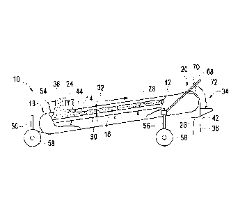
Referring now in detail to Figures 1. through 4, an apparatus 10 according to
the present
invention is illustrated. The apparatus 10 comprises a conveyor 16 within a
housing 12, the
conveyor 16 positioned generally horizontally to provide a low profile to
enable positioning of
the apparatus 10 underneath a hopper-bottom bin or similar seed storage unit,
the conveyor
configured to move seed 36 on the top of the conveyor 16 in the direction of
the arrow in Figure
1. The housing 12 comprises a seed intake 24 at a first end 18 of the conveyor
16 and a seed
outlet 26 at a second end 20 of the conveyor 16. While various drive
mechanisms are possible
within the scope of the present invention, a conventional motor 22 is shown in
the illustrated
embodiment as being mounted on a side of the housing 12 for providing power to
the conveyor
16, the motor being connected to a power source 74 and a controller 50 in a
manner determinable
by those skilled in the art.
The conveyor 16, which is a continuous belt in the embodiment shown in Figures
1 through 5, is
provided with a series of spaced apart cleats 28, the cleats mounted on the
conveyor 16 at a first
edge 30, the second edge 32 of each cleat 28 directed toward an inner surface
14 of the housing
12. The cleats 28 are equally spaced along the conveyor 16 and rigidly mounted
perpendicular
to the conveyor surface to avoid forward or rearward bending when retaining
and transporting
seed 36; it: will be obvious to those skilled in the art, however, that the
cleats 28 could be
mounted in such a way that they are disposed off of the vertical and still
achieve the desired
functionality. In the result, the conveyor 16, two adjacent cleats 28 and
surrounding housing 12
walls define a generally cuboid receiving void for receipt and transport of
seed 36 to be treated,
and the series of equally spaced cleats 28 therefore provide a continuous
series of such voids of
equal volume. The consistency of volumes in series allows calculation of an
appropriate amount -
of treatment 38 application. The cleats 28 are also preferably composed of a
flexible material to -
avoid crushing of seed 36 that might get caught against the housing 1.2 inner
walls during
movement of the conveyor 16.
Figures 12a and 12b illustrate an alternative conveyor I6a, which is in the
form of a horizontally
disposed wheel that rotates about a vertical axis. Rather than the continuous
belt configuration
of Figures 1 through 5 with cuboid voids, this alternative embodiment
illustrates a further
Configuration that embodies the present invention where the voids are
generally triangular. The
CA 02877860 2014-12-17
WO 2014/008571 PCT/CA2012/000641
8
conveyor I 6a is housed within a circular housing 12a and rotates about its
vertical axis in the
direction shown by the arrow in Figure 12b, the voids defined in part by
cleats 28a. The intake
24a is located at a first end 18a of the conveyor 16a and comprises an
aperture in the upper
surface of the housing 12a, which aperture opens into a triangular void. Seed
can be deposited
into the triangular void through the intake 24a. As can be seen in Figure 12b,
the intake 24a may
be larger than the width of an individual void, which has been found to be
helpful in ensuring a
complete filling of the void at certain higher operating speeds. Once an
individual void is filled,
it is rotated out of alignment with the intake 24a (through the action of a
drive mechanism, which
could for example be situated beside or under the housing .12a) and towards
the outlet 26a, which
comprises an aperture located at a second end 20a of the conveyor 16a in the
lower surface of the
housing 12a; once the void is positioned over the outlet 26a the seed is
allowed to fall
downwardly out of the void through the outlet 26a. In this way, the
alternative conveyor 16a
functions in a similar manner to the conveyor 1.6 of Figures 1 through 5,
although empty voids
return to the intake 24a on the same horizontal plane as the filled voids
rather than passing
rearwardly on the underside of the belt-like conveyor 16. The conveyor 16a and
housing 12a
could also be provided with a channeling collar as is illustrated in Figure 1,
to channel seed
toward the intake 24a, or the housing 1.2a could be raised into position
against a bin outlet by
Means known in the art. Other alternative conveyor configurations will be
obvious to one skilled
in the art.
As can best be seen in Figures 1 and 3, the housing 12 comprises a channeling
collar 54 mounted
on the intake 24. The collar 54 is composed of a flexible material that folds
in an accordion-like
fashion. The collar 54 may be positionable in any degree of upward extension,
or it may be
biased upwardly into an extended position by means known to those skilled in
the art such as
external or internally integrated springs. The purpose of the collar 54 is to
channel seed 36 from -
an overlying storage unit toward the intake 24, which collar 54 may be spaced
from the storage
unit outlet or sealingly engaged with it. This feature allows the user to
avoid seed loss due to
misalignment of the storage unit outlet and the intake 24 and also due to
wind. The collar 54
also functions to allow flooding of the conveyor 16 with seed 36 to ensure
accuracy of volume
flow determination.
CA 02877860 2014-12-17
WO 2014/008571
PCT/CA2012/000641
9
The apparatus 10 is also provided with a handle 68 and wheels 58 to enable a
user to move the
apparatus 10 into position beneath a seed storage unit. The wheels 58 can be
caster wheels, and
they are mounted on extensible legs 56 in the illustrated embodiment, as can
best be seen in
Figures 1, 3 and 4. The extensible legs 56 allow the user to vertically adjust
the rear of the
apparatus 10 to better position the intake 24 for receipt of seed 36, but also
to raise the front of
the apparatus 10 slightly to enhance the area for spraying treatment 38 on the
metered seed 36.
Figures 1 and 2 show the position of a scraper or brush 44 which is mounted on
the inner surface
14 of the housing 12 adjacent the intake 24. The brush 44 is an elongate
member that extends
across the width of the housing 12 and is generally equivalent in length to a
cleat 28. The brush
44 functions to help level off the seed 36 that has been received in each
cuboid void, helping to
ensure consistent seed 36 volumes in each void. Figure 5 provides a detailed
illustration of the
interface between the brush /44 and a cleat 28. While the void could be
initially filled above the
second edge 32 of the cleat 28, the conveyor 16 moves the cleats 28 and
received seed 36 past
the brush 44, thereby scraping off the excess seed 36 such that it remains in
the intake 24 area. It
will also be obvious to those skilled in the art that the edge of the intake
24 could serve the same
function as the brush 44 in modified or unmodified form in alternative
embodiments of the
present invention.
The above description is addressed to the metering functionality of the
apparatus 10, whereby
determinable volumes of seed 36 in each cuboid void result in a determinable
volume flow
through the apparatus 10. The apparatus 10 is also provided with seed treating
functionality,
where the metered seed 36 is provided with treatment 38. The seed treatment
applicator 34 is
positioned at the front end of the apparatus I() over the conveyor outlet 26
and comprises a
housing for directing metered seed 36 downwardly past a spray nozzle 48. A
pump 46 (such as a .
peristaltic pump) is mounted on a side of the housing 12 for drawing treatment
38 from a .
treatment source 40 such as a barrel, and the pump is connected to both a
power source 74 and
the controller 50. The pump 46 is configured to draw treatment 38 from the
treatment source 40
and direct the treatment 38 through treatment lines 72 toward the nozzle 48.
AS can be seen in
the detailed illustration of Figure 6, the treatment line 72 can be connected
to valves 76 and a
pressure gauge 70 in a conventional manner to control and monitor the passage
of treatment 38.
CA 02877860 2014-12-17
WO 2014/008571
PCT/CA2012/000641
As can be seen in Figure 8, the treatment 38 is sprayed rearwardly within the
seed treatment
applicator 34 housing, as the seed 36 passes downwardly from the conveyor
outlet 26 and past
the nozzle 48 to the treated seed outlet 42. Although not shown, it is
possible to incorporate a
second nozzle on a rearward side of the seed treatment applicator 34 housing
opposite to the
nozzle 48, with spray toward the front of the apparatus 10, such that seed 36
is sprayed from
front and back as it falls toward the treated seed outlet 42.
Figures 8 and 9 illustrate the interface of the apparatus 10 with adjacent
equipment. Figure 8
illustrates the apparatus 10 receiving seed 36 from a hopper-bottom bin 64,
where the collar 54 is
upwardly extended to sealingly engage the bin outlet 66. As can be seen, this
form of .
engagement has the advantage of keeping the intake 24 consistently full during
operation of the
apparatus 10 while reducing the chance of spillage or wind loss. Figure 9
illustrates the
positioning of an auger hopper 60 and mixing auger 62 at the discharge end of
the apparatus 10.
After the seed 36 has been sprayed with treatment 38, it falls through the
treated seed outlet 42
into the hopper 60, where the seed 36 is then drawn up into the auger for
mixing and more
uniform coating of the seed 36 before being ultimately discharged into a truck
or another storage
unit. Although not shown, the auger hopper 60 could also be integrated with
the front end of the
apparatus 10 rather than be a separate piece of equipment, thereby further
reducing exposure
points.
The controller 50 is connected to both the conveyor motor 22 and the pump 46,
and is used to
control both the speed of the conveyor 16 and the rate of treatment 38
application, as will be
discussed below. The controller 50 comprises a programmable logic controller,
a data storage, a =
user interface and a display. The user interface and display are collectively
a touchscreen 52, as
seen in Figure 2.
As has been indicated above, certain prior art seed treaters meter the seed to
be treated but rely
on volume alone to calculate treatment application rate, which does not take
into account seed
density, and the volume figure itself is subject in most cases to significant
error. The apparatus
10 described above, while providing many advantages over prior art systems, is
intended to
address the error in volume determination in a low profile configuration.
Methods according to
CA 02877860 2014-12-17
WO 2014/008571
PCT/CA2012/000641
11
the present invention, in contrast to prior art methods, use mass -flow based
on density and
therefore are able to provide a more accurate determination that aligns with
the standard
application rates provided by most treatment manufacturers.
Standard application rates are normally provided in mL/ lOOkg, or volume/mass.
Density is mass
per unit volume, so if one knows the density for a particular seed to he
treated, the mass can be
determined based on that density and a measured seed volume, allowing the user
to calculate an
optimal application rate. The following two examples are illustrative of a
method according to
the present invention.
Example 1: Applying Mud MO Liquid Seed Treatment to Wheat
A first test run was conducted using an apparatus in accordance with the
present invention. The
test apparatus had a single-revolution volume of 1.44 bushels, which figure
was programmed
into the controller to enable motor speed calculations.
Using a scale and a half-litre cup, the actual density of the seed was
measured, rather than use a
standard density which can be inaccurate. For example, in the instant example,
the actual
measured seed density was 67.8 lbs/bushel rather than the standard of 60
ths/bushel. The
application rate of Raxil MD is 300 mL/100kg of seed.
For every revolution of the conveyor, the unit displaced 1.44
bushels/revolution X 67.8
lbs/bushel = 97.6 lbs/revolution or 44.3 kg/revolution. As .Raxil MD was to be
applied at 300
mli1.00kg of seed, the apparatus pump had to apply 44.3 kg/revolution X 300
tn1/100kg = 132
mUrevolution. The desired treating speed was 20 bushels of seed per minute, so
the conveyor
was operating at (20 bushels/minute)/(1.44 'bushels/revolution) = 13.9 rpm.
Therefore, to
achieve the desired application rate of R.axil MD Seed Treatment, the pump was
operated at 132 ,
m.Urevolution X 13.9 rpm .= 1845 mUminute.
Example 2: Applying Read WW Liquid Seed Treatment to Barley
CA 02877860 2014-12-17
WO 2014/008571 PCT/CA2012/000641
12
A second test run was conducted using an apparatus in accordance with the
present invention.
Using a scale and a half-litre cup, the actual density of the seed was
measured, rather than use a
standard density which can be inaccurate. For example, in the instant example,
the actual
measured seed density was 55.4 lbs/bushel rather than the standard of 48
lbs/bushel. The
application rate of Raxil WW is 363 mU100kg of seed.
For every revolution of the conveyor, the unit displaced 1.44
bushels/revolution X 55.4
lbs/bushel = 79.8 lbs/revolution or 36.2 kg/revolution. As Raxil WW was to be
applied at 363
mU100kg of seed, the apparatus pump had to apply 36.2 kg/revolution X 363
m1.1100kg = 131.3
mUrevolution. The desired treating speed was 18 bushels of seed per minute, so
the conveyor
was operating at (18 bushels/minute)/(1.44 bushels/revolution) = 12.5 rpm.
Therefore, to
achieve the desired application rate of Raxil WW Seed Treatment, the pump was
operated at
131.3 mUrevolution X 12.5 rpm = 1642 mUminute.
Turning now to Figures 10 and 11, methods according to the present invention
arc illustrated. In
the method 80 illustrated in Figure 10, seed is provided at step 82, followed
by a determination
of seed density at step 84. The seed is then metered at step 86 to determine
the seed volume, and
the seed density is used at step 88 to convert that seed volume value to a
seed mass value. The
seed mass value is then used at step 90 to calculate an optimal seed treatment
application rate,
followed by actual application of treatment at step 92.
In the method UX) illustrated in Figure 11, seed is provided at step 102 and a
metering apparatus
such as apparatus 10 described above is provided at step 104. The seed density
is determined at
step 106. As indicated in the above examples, seed density can be determined
using a simple
scale-and-cup method; alternatively, where a conveyor-based metering apparatus
is employed as
in the present invention, the conveyor itself could be provided with a
weighing mechanism such
as a load cell to weigh the loaded conveyor and thereby determine seed density
without recourse
to a separate measurement step using a scale and cup. The seed is metered
using the apparatus at
step 108 (either concurrently with or subsequent to step 106) to determine a
seed volume flow
through the apparatus. This seed volume flow through the apparatus is then
converted at step
110 to a seed mass flow through the apparatus using the seed density that was
determined at step
CA 02877860 2014-12-17
WO 2014/008571
PCT/CA2012/000641
13
106, The optimal seed treatment application rate is then calculated at step
112 based on the seed
mass flow through the apparatus, followed by actual application of treatment
at step 114.
As indicated above, the apparatus 10 is provided with a controller 50 to
enable operation of the
apparatus 10 and implementation of the methods according to the present
invention. Turning
now to Figures 7a to 7g, screen shots are provided which illustrate the use of
the controller 50
with touchscreen 52. When the controller 50 has been powered up, Figure 7a is
the first screen
that is presented to the user. This main screen is facilitates operation of
the controller 50.
When the user presses the "Prime/Empty" button on the touchscreen, the
Prime/Empty Screen is
presented to the user, as shown in Figure 7b. This screen is used to prepare
the apparatus 10 for
operation. The "Jog Conveyor" button is used once the bin seed supply has been
initiated and
the intake 24 has been flooded with seed 36; by pressing the button, the
conveyor motor 22 is
powered up so as to advance the conveyor 16 one cleat 28 at a time. The
"Prime" button is used . .
to pump treatment 38 from the treatment source 40 to the pump 46 and into the
nozzle 48. The
"Empty" button runs the pump 46 in reverse to return unused treatment 38 to
the treatment
source 40 at the completion of treatment.
If the user selects the "Recipes" button the main screen, the user is
presented with the Main
Recipe Screen shown at Figure 7c. This screen presents the user with a list of
pre-programmed
"recipes" or settings that are required for treatment application for
different seed types. Pre-
programming such settings allows the user to quickly return to needed
settings.
When the user selects one of the recipes on the Main Recipe Screen, the user
is presented with a
Recipe Setting Screen for the particular seed type, an example of which is
shown at Figure 7d.
This Recipe Setting Screen contains the information necessary for the proper
control of the
conveyor motor 22 and pump 46, The user can enter a recipe name (a keypad pops
up upon
selecting this item) and must enter a seed density, which seed density can be
determined using a
half-litre cup and scale as indicated above, As stated above, this seed
density is used by the
controller to convert the volume flow of the conveyor 16 to a mass flow. The
application rate
must also be entered by the user and is normally found on the treatment
product label, expressed
CA 02877860 2014-12-17
WO 2014/008571
PCT/CA2012/000641
14
.in mL/100kg. The pump calibration number defaults to 1000 which is 100%, but
this can be
changed manually or through a pump test.
If the user presses the pump test button on the Recipe Setting Screen, they
are presented with. the
Pump Calibration Screen shown at Figure 7e. This screen is used to account for
different seed
treatment fluid viscosities, as fluids of different viscosities will move
through. the pump 46
differently. During the pump test, the pump 46 is operated for 30 seconds, the
liquid is collected,
and the volume is measured, The user enters the volume at the "Amount of
Treatment
Collected" line, and the controller calculates the volume pumped per
revolution of the motor 22.
Returning to the Main Screen, the user can then select the "Operation" button
and will be
presented with the Operation Screen shown at Figure 7f. This screen is
displayed prior to and
during operation of the apparatus 10. Once "Start" has been selected, the
apparatus 10 will begin
running and the "Start" button will disappear and be replaced on the
touchscreen 52 with a red . .
"Stop" button ¨ pushing the "Stop" button will cause the motor 22 and pump 46
to shut off.
Operation of the apparatus 10 will proceed on the basis of the selected seed-
specific recipe and
application rate (shown as bushels/minute and lbs/minute on the screen), both
of which are
displayed on the screen. The controller calculates how fast to turn the
conveyor 16 based on the
bushels required per minute, and uses the seed density to convert this volume
to a mass flow
through the apparatus 10. The mass flow is required as the application rate of
treatment entered
in the recipe is based on .ml../100kg. From this information, the controller
then calculates how
fast to turn the pump 46 to get the calculated optimal application rate of
treatment. The
controller uses proportional control to operate the pump 46 at the correct
speed relative to the
conveyor 16 speed; in. this way the application rate is as desired regardless
of the seed flow
selected, and this control reduces the amount of calibration necessary when
changing products
and flow rates.
As can be further seen in Figure 7f, the controller allows the user to select
a certain batch size of
seed 36 to be treated. By pressing the square to the right of the "Batch Size"
label on the
touchscreen 52, a further screen appears allowing the user to enter a seed
amount in lbs. If a
batch amount is entered, then the "lbs Treated" line is activated and tracks
the amount of seed
CA 02877860 2014-12-17
WO 2014/008571 PCT/CA2012/000641
left to be treated in the batch. in this batch mode of operation, the unit
will run until the set-point
is reached and then the pump 46 and conveyor 16 will be shut off. If "0" is
chosen as the batch
size, the unit will run continuously until the "Stop" button is pressed on the
touchscreen 52, and
the "lbs Treated" line will display the seed that has been treated as the unit
is running. The
conveyor rpm and pump rpm are also displayed, and will display "0" until the
unit is running.
From the Main Screen, the user can also select the "Totals" button, which will
display a Totals
Screen as shown in Figure 7g. This screen tracks the treatment in progress,
with options to track
and save data for two batches and the treatment used. The screen also displays
the lifetime
treatment total of seed for the unit. From the Main Screen, the user can also
select the
"Setup/Maintenance" button, which can display a screen (not shown) for
changing units from
Imperial to Metric or any number of other settings.
As can be readily seen, then, the apparatus and method of the present
invention present
significant advantages over the prior art. For example, the apparatus provides
for metering based =
on positive displacement instead of an inaccurate screw-type auger, with a low
profile due to a .
horizontally disposed conveyor (both the belt-type conveyor and circular
conveyor) so it can fit
under common hopper-bottom bins. Also, the apparatus and methods according to
the present
invention incorporate a seed density determination to provide more accurate
treatment
application. Other advantages would be obvious to those skilled in the art.
The foregoing is considered as illustrative only of the principles of the
invention. Thus, while
certain aspects and embodiments of the invention have been described, these
have been
presented by way of example only and are not intended to limit the scope of
the invention.
Indeed, the invention described herein may be embodied in a variety of other
forms without
departing front the spirit of the invention, which invention is defined solely
by the claims below.