Note : Les descriptions sont présentées dans la langue officielle dans laquelle elles ont été soumises.
CA 02877955 2014-12-24
WO 2014/004849 PCT/US2013/048224
SYSTEM FOR PROCESSING AND PRODUCING AN AGGREGATE
CROSS REFERENCE TO RELATED APPLICATIONS
[0001] This application claims priority to United States Provisional
Application No. 61/665,987,
filed June 29, 2012, entitled SEPARATOR, to United States Provisional
Application No.
61/675,794, filed July 25, 2012, entitled SPIRAL SEPARATOR, and to United
States Provisional
Application No. 61/691,173, filed August 20, 2012, entitled SPIRAL OR HELICAL
SEPARATOR DEVICE, SYSTEM AND A NOVEL METHOD FOR SORTING OR
PURIFYING A FRAC SAND OR A PROPPANT, the contents of which are hereby
incorporated
by reference in their entirety.
FIELD OF THE INVENTION
[0002] The present invention relates to aggregate particles. More
specifically, the present
invention relates to a novel process and system for the processing and
production of aggregate
particles. The resulting aggregate particles may include proppants usable in
the oil or gas
industry to prop open subterranean fractures around oil and gas wells, or in a
gravel-packing
operation, such as for sand control.
BACKGROUND
[0003] Aggregates and proppants are generally known in the art. An aggregate
is a component
of a composite material which provides certain properties to the composite
material, including
bulk and/or resistance to compressive stress. A proppant, which is a type of
an aggregate, is a
material used to hold open or "prop" an area in which the proppant is
introduced. In the oil or
gas industry, a proppant is typically used in association with hydraulic
fracturing operations, and
in sand control, such as in gravel-pack operations.
[0004] During the hydraulic fracturing process, a conductive fracture is
induced underground in
order to provide a path of extraction for a targeted subterranean material,
such as a hydrocarbon,
including oil or gas. Typically, a fracturing fluid is introduced into the
targeted subterranean
area. The fracturing fluid creates hydraulic fractures underground to the
targeted subterranean
CA 02877955 2014-12-24
WO 2014/004849 PCT/US2013/048224
materials. The hydraulic fractures provide a path for the targeted
subterranean materials to be
extracted, for example through an underground well. In order to keep the
induced hydraulic
fractures open, to maintain the fracture width, and/or to slow the decline of
the fractures, a
proppant is typically introduced into the hydraulic fractures. The proppant
slows and/or inhibits
closure of the fractures when the fracturing fluid is reduced. Accordingly, an
appropriate
proppant has the ability to flow into the fractures, the ability to form a
"pack" or a partial
monolayer that provides support and maintains the fractures in an open state,
the ability to
withstand substantial crushing force in the subterranean area (i.e. crush
resistance), and the
ability to facilitate flow of a hydrocarbon to an extraction bore or to a well
head.
[0005] The volume and rate of hydrocarbon production through subterranean
fractures or a
wellbore can be a function of proppant conductivity. Proppant conductivity is
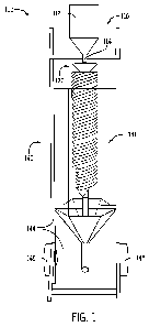
the product of
proppant permeability and fracture width. Hydrocarbon production rate can also
be influenced
by fracture length and the contact area of fractures with reservoir
hydrocarbons. For example, an
increase in proppant conductivity, fracture length, or fracture contact area
with reservoir
hydrocarbons can increase the hydrocarbon productivity of a well. Similarly, a
decrease in
proppant conductivity, fracture length, or fracture contact area with
reservoir hydrocarbons can
decrease the hydrocarbon productivity of a well.
[0006] Due to the necessary requirements of a proppant in hydraulic
fracturing, only certain
materials are suitable for use as a proppant. For example, some naturally
occurring sands,
known as "frac sand," meet these requirements. Other materials used as a
proppant include, but
are not limited to, glass beads, steel shot, nut shells, ceramic pellets,
synthetic resin pellets,
sintered alumina or bauxite, a polymer, shells, or a mixture of any of these
materials.
[0007] When designing or selecting a proppant, several proppant properties
typically are taken
into consideration, as the properties can affect proppant performance to
achieve proppant
conductivity, fracture length, and ultimately hydrocarbon production. As some
of these
properties can conflict with each other, the benefit and the cost typically
needs to be considered
prior to the design or selection of the proppant for a targeted application.
In addition, the
targeted application can vary depending upon certain factors of a well,
including, but not limited
to, formation type, formation depth, the treatment to be applied, and/or the
equipment to be used.
[0008] For example, compressive forces in a fracture can often exceed 1,000
pounds per square
2
CA 02877955 2014-12-24
WO 2014/004849 PCT/US2013/048224
inch or psi. A significant fraction of particulates making up a proppant can
withstand these
compressive forces without crushing or substantially breaking. A frac sand or
a lightweight
ceramic is often used in applications where compressive forces are less than
about 10,000 psi,
such as for relatively shallow wells. In deeper wells, where compressive
forces can exceed
15,000 psi, higher strength proppants are typically used. These higher
strength proppants are
often composed of materials having a relatively higher specific gravity than
other proppants,
such as ceramic or bauxite.
[0009] The crushing of a proppant has certain disadvantages, including a
reduction in fracture
width or close and "pinch off' of a fracture, reducing proppant conductivity.
In addition, fines
generated from a crushed proppant can clog a proppant pack void space,
reducing proppant pack
permeability, and thus reducing proppant conductivity. Further, sharp-edged
fines may be
generated from a crushed proppant. These sharp-edged fines can concentrate the
compression
force onto an adjacent particle sphere, leading to the crushing of the
adjacent particle and
subsequent release of additional sharp-edged fines.
[0010] While a proppant having a higher specific gravity can improve crush
resistance,
transportability of the proppant is often compromised, requiring higher
viscosity pumping fluids
and/or higher pumping rates. In addition, proppants having a higher density
generally have
higher material costs. This is in addition to additional costs for larger
pumping equipment and
increased wear rates of fluid carrying equipment.
[0011] As another example, the size range of particles making up a proppant is
typically
relatively narrow and historically controlled through fractionation using
sieves. The size range
of particles is typically measured in terms of the diameter of the particles.
An example of size
range distributions of a proppant include, but are not limited to, 6/12, 8/16,
12/18, 12/20, 16/20,
16/30, 20/40, 30/50, 40/60, 40/70, 70/140, and 100 Mesh as according to U.S.
sieve pan sizes
used to fractionate the proppant. Narrower size range distributions of a
proppant are
commercially produced, for example for a ceramic proppant. For example, these
narrower size
range distributions may include 18/20, 20/30, and 30/40. Generally, a narrower
size range
distribution of a proppant maintained under stress can improve conductivity
through increased
proppant permeability. However, Median Particle Diameter (MPD) of a proppant
can also
significantly affect conductivity, as generally the larger the MPD,
particularly when maintained
under stress or pressure, the greater the conductivity.
3
CA 02877955 2014-12-24
WO 2014/004849 PCT/US2013/048224
[0012] A proppant having particles of a smaller MPD can exhibit a higher crush
strength and a
longer transport distance due to a reduced settling rate. Both of these
factors can promote
fracture productivity. However, an increase in fracture length and a
corresponding increase in
accessibility to reservoir hydrocarbons must be weighed against potentially
reduced permeability
and associated reduced conductivity of the proppant pack formed by these
particles. A reduction
in permeability and conductivity can reduce fracture productivity.
[0013] On the other hand, a proppant having particles of a larger MPD,
particularly when
maintained under stress, can exhibit relatively high permeability and high
conductivity,
promoting fracture productivity. However, these particles can settle
relatively faster,
compromising fracture length and potentially reducing accessibility to
hydrocarbons and fracture
productivity. Further, these particles can have a reduced crush resistance.
Thus, upon crushing
can reduce MPD, fracture width, reducing proppant permeability and
conductivity.
[0014] As another example, the shape of particles in a proppant can profoundly
impact its
conductivity. Historically, proppants have been sought that have a spherical
and rounded shape
to maximize load bearing capacity and to even stress distribution, and
maximize corresponding
crush resistance, permeability, flowability, delivery distance within a
fracture, effective fracture
width through reduced embedment, and reduced pressure loss, tortuosity,
friction against
hydrocarbon flow, and abrasion. Together, these shape-dependent properties can
serve to
increase the effective conductivity of a proppant, and ultimately increase
hydrocarbon production
rates.
[0015] Packing together spheroidal or largely spherical and rounded particles
can form capillary-
like flow channels through a proppant matrix, leading to reduced tortuosity,
and associated
reduced pressure loss. This is of particular importance in areas of high flow
rates, such as near a
well bore or areas of fracture convergence. In these areas, fractures and
fluid flow converge and
Non-Darcy flow effects can be most pronounced. While spheroidal particles of
uniform size
offer excellent conductivity, these particles can be prone to flow-back into
the well bore. Flow-
back of a proppant is undesirable as it can reduce the volume of proppant in
the fractures,
reducing the productivity through the fractures. Further, proppant flowing
back into the well
bore and to the surface can abrade well bore components and surface equipment,
leading to
expensive equipment repair, equipments replacement, and costly downtime.
Additional costs
can be incurred for the removal and disposal of flow-back proppant from the
oil and gas
4
CA 02877955 2014-12-24
WO 2014/004849 PCT/US2013/048224
produced from the well bore.
[0016] As another example, the surface texture of particles in a proppant can
impact proppant
performance. A smooth surface texture can offer certain advantages, such as a
reduced
coefficient of friction. A reduced coefficient of friction can reduce flow
friction, resulting in an
increase in flow capacity of a fluid through a fracture. Conversely,
irregularities on the outside
surface of a proppant can lead to uneven stress distribution, proppant
crushing, and fine
generation. Further, surface irregularities can trap fracturing fluid used
during injection, closing
up a void space in a proppant pack and reducing proppant permeability and
conductivity. This in
turn reduces oil or natural gas production. Additionally, a prolonged clean-up
of injection fluid
can be expensive and cause delays in oil or natural gas production.
[0017] Surface irregularities, for example in the form of dents, protrusions,
burs, rough surface
textures, or angular edges has the additional disadvantage of a high degree of
abrasiveness. The
presence of an abrasive particle in the well bore during injection or
production can damage well
and pumping equipment, increasing tool and equipment costs and leading to
costly well
downtime. However, surface irregularities potentially can reduce proppant flow-
back.
[0018] In addition, the presence of clusters in a proppant can have adverse
affects on the
proppant. A cluster is formed of many small granular particles, and has a
rough surface texture.
Clusters can reduce the strength of the proppant, increase flow friction, and
ultimately reduce
proppant conductivity. Clusters are often found in frac sand.
[0019] The presence of contaminant particles in a proppant can also have
adverse affects on the
proppant. Contaminant particles are often found in frac sand, and may include
feldspar, mica,
magnetite, hematite, biotite, milky quartz, iron ore, and/or dolomite.
Contaminant particles can
reduce proppant strength, increase acid solubility, increase abrasiveness,
increase flow friction,
and ultimately reduce proppant conductivity.
[0020] As another example, additional requirements for a proppant can include
chemical
inertness towards fracturing fluid crosslinkers and breakers, and acid
tolerance.
[0021] Progress has been made to optimize functionality of certain synthetic
proppants, such as
ceramic proppants. For example, a lightweight ceramic proppant can have a
relatively low
specific gravity, and a high degree of sphericity and roundness. However,
production costs of
synthetic proppants can be high and further increased when the particle size
distribution is
CA 02877955 2014-12-24
WO 2014/004849 PCT/US2013/048224
narrowed. In addition, synthetic proppants can be highly abrasive and can
incur additional costs
related to equipment damage, tooling damage, and well downtime when used.
[0022] Frac sand, while relatively inexpensive, typically includes a
heterogeneous mixture of
particle shapes, which include irregularly shaped particles and highly
spherical and rounded
particles. Further, frac sand typically includes a heterogeneous mixture of
particle surface
textures, and may also include clusters and/or contaminants. Where some
particles of frac sand
have a smooth surface texture, other particles have a rough surface texture.
Irregular or angular
shaped frac sand particles, or particles having a rough surface texture can
have a detrimental
impact on conductivity, and ultimately can reduce the rate of hydrocarbon
production. In
addition, the abrasiveness of these frac sand particles incurs additional
costs related to equipment
damage, tooling damage, and well downtime when used.
[0023] Similar to frac sand, resin-coated frac sand or resin-coated sand
includes a relatively
heterogeneous mixture of particle shapes, including irregularly shaped
particles and highly
spherical and rounded particles. While a resin coating can slightly improve
sphericity or
roundness of a frac sand particle, significant irregularities in shape within
the particle population
remain. Resin-coated sand can be used near the well bore, a zone of high fluid
velocity and
turbulence, in order to reduce proppant flow-back into the well. A resin-
coating can also reduce
fine generations, and maintain a high structural integrity of proppant by
improved crush
resistance. This together acts to optimize conductivity and hydrocarbon flow
through the well
bore. However, resin chipping can lead to clogged void space, reduced
permeability, and
reduced strength of the resin-coated sand. In addition, resin-coated sand
requires a costly special
treatment which can be negatively affected by temperature.
[0024] Currently, no processing system exists that through direct modification
can increase
sphericity and roundness of frac sand to produce a generally highly spherical
and rounded frac
sand without also introducing surface irregularities or pre-stress particles
of the frac sand. For
example, while a sand reclamation system can be used to rub together frac sand
particles in order
to increase the sphericity and roundness of the particles, in doing so, dents
and/or protractions
can result on the surface of the particles. In another example of a system, a
frac sand particle is
repeatedly shot at high velocity against a metal plate to achieve a spherical
and rounded particle
shape. However, this process can lead to pre-stressing or fracturing of the
particle, reducing
crush resistance of the particle. In addition, in both system examples,
significant waste is
6
CA 02877955 2014-12-24
WO 2014/004849 PCT/US2013/048224
incurred during shape modification to the frac sand particles.
[0025] In addition, no processing system exists that can remove abrasive
particles from a frac
sand to produce an abrasion-resistant frac sand. An attrition scrubber can be
used to remove a
surface irregularity from a frac sand particle, reducing the roughness of
surface texture and
associated abrasiveness of the frac sand particle. However, an attrition
scrubber is unable to
significantly remove or affect relatively more angular, un-spherical, or
irregularly shaped
particles or clusters, or particles having a rough surface texture. These
abrasive particles remain
in the frac sand processed by an attrition scrubber.
[0026] Due to the disadvantages of irregularly shaped, rough surface texture
sand, there is a need
for a sand that is of highly spherical and rounded shape, is smooth of surface
texture, yet retains
the benefits of a low specific gravity. Further, a sand size gradation or MPD
is currently not
necessarily optimized for one or more proppant properties. There is a need for
the ability to
further modify a sand size gradation or MPD to result in optimal performance
or economics of a
proppant. In addition, there is a need for a more abrasion-resistant proppant
that is less abrasive
than a typical frac sand or a synthetic proppant, such as a ceramic proppant.
[0027] Furthermore, there is a need for a sand that exhibits greater
permeability and
conductivity, particularly for use near or adjacent to the well bore. This
sand can be resin-
coated, such as to further reduce flow-back, reduce fine generation, or to
increase the strength of
the sand. Furthermore, there is a need for a sand that would be an alternative
to resin-coated
sand, as the sand would not require resin-coating of particles, but that
similarly reduces proppant
flow-back.
[0028] In addition, due to the limited number of naturally-occurring aggregate
particle deposits
for certain uses, there is a need for a system of processing aggregate
particles to acquire particles
having certain desired properties. For example, there are a limited number of
naturally-occurring
aggregate particle deposits, such as sand, suitable for use as a proppant. As
another example,
there are a limited number of naturally-occurring aggregate particle deposits,
such as sand,
suitable for use in other industries, including, but not limited to, sand
blasting, molding, shot
peening, concrete, masonry, landscaping, agriculture, artificial turf,
electronics, or filtration.
[0029] In addition, shipping of an aggregate particle can be expensive, and
can economically
limit access to certain aggregate particles. More specifically, while an
aggregate particle of a
7
CA 02877955 2014-12-24
WO 2014/004849 PCT/US2013/048224
distant deposit may have one or more beneficial properties, it can be cost
prohibitive to ship
compared to a local deposit. Accordingly, there is a need for a system of
processing aggregate
particles which may be movable.
SUMMARY OF THE DESCRIPTION
[0030] The present invention provides an improved system for processing and
producing a
hydraulic fracturing proppant or a proppant for use in sand control methods,
such as in a gravel-
pack. The present invention provides a system for processing relatively
inexpensive materials,
such as sand and/or silica sand, to produce a proppant having the desired and
suitable properties
to serve as an effective hydraulic fracturing proppant. In addition, the
present invention provides
a system which can be mobile. Further, the present invention provides for the
production of a
value added proppant suitable to serve as an effective hydraulic fracturing
proppant or for use in
sand control.
[0031] A proppant is provided. The proppant results from a separator means and
comprises a
plurality of particles. The particles have an average Krumbein and Sloss
Sphericity Value of 0.6
or above, and an average Krumbein and Sloss Roundness Value of 0.6 or above.
[0032] A proppant resulting from a separator means which separates a feed
stock is also
provided. The proppant comprises a plurality of particles, the particles have
an average
Krumbein and Sloss Sphericity Value of at least 0.01 greater than the average
Krumbein and
Sloss Sphericity Value of the feed stock. The proppant includes a plurality of
particles, the
particles have an average Krumbein and Sloss Roundness Value of at least 0.01
greater than the
average Krumbein and Sloss Sphericity Value of the feed stock. In addition, a
proppant is
provided that can include a larger or smaller MPD or a modified size
distribution profile
compared to the feedstock through use of the separator means or screening
apparatus.
[0033] An aggregate resulting from a processing means which separates a feed
stock is also
provided. The aggregate includes a plurality of particles, the particles have
an average median
particle diameter of at least 1 micron more than the average median particle
diameter of the feed
stock.
[0034] A proppant processing assembly is also provided. The processing
assembly includes a
separator assembly having a central member extending from a first end to a
second end, the
8
CA 02877955 2014-12-24
WO 2014/004849 PCT/US2013/048224
central member supporting at least one helical flight provided between the
first and second ends,
the helical flight having a width provided between a proximal end and a distal
end. An assembly
housing is provided around a portion of the separator assembly, the assembly
housing includes a
collection portion for receiving processed feed stock which exits the
separator assembly radially
away from the central member outward past the distal end, and the collection
portion includes a
first outlet. A second outlet is coupled to the separator assembly for
receiving a second fraction
of processed feed stock which exits the separator assembly at the second end
of the at least one
helical flight.
[0035] A recombinant aggregate is also provided. The recombinant aggregate
includes a first
aggregate fraction resulting from a processing means, the first aggregate
having a first particle
size profile, a second aggregate fraction resulting from a processing means,
the second aggregate
having a second particle size profile, wherein the first and second aggregate
fractions are
combined at a ratio such that the resulting mixture has a third particle size
profile different from
the first particle size profile and second particle size profile.
[0036] A recombinant aggregate is also provided. The recombinant aggregate
includes a first
aggregate fraction resulting from a processing means, the first aggregate
having a first particle
shape profile, a second aggregate fraction resulting from a processing means,
the second
aggregate having a second particle shape profile, wherein the first and second
aggregate fractions
are combined at a ratio such that the resulting mixture has a third particle
shape profile different
from the first particle shape profile and second particle shape profile.
BRIEF DESCRIPTION OF THE DRAWINGS
[0037] FIG. 1 is an isometric view of one or more examples of embodiments of a
processing
assembly for the production of a proppant.
[0038] FIG. 2 is front elevation view of the processing assembly of FIG. 1,
illustrating the front
side of the processing assembly and the containment shield in an open
position.
[0039] FIG. 3 is a rear elevation view of the processing assembly of FIG. 1,
illustrating the back
side of the processing assembly and the containment shield in an open
position.
[0040] FIG. 4 is an isometric view of a portion of the processing assembly of
FIG. 1, illustrating
the separator assembly of the processing assembly and the containment shield
in an open
9
CA 02877955 2014-12-24
WO 2014/004849 PCT/US2013/048224
position.
[0041] FIG. 5 is a close up view of a portion of the processing assembly of
FIG. 1, taken along
line 5-5 of FIG. 4.
[0042] FIG. 6 is a close up view of a portion of the processing assembly of
FIG. 1, taken along
line 6-6 of FIG. 4.
[0043] FIG. 7 is a close up view of a portion of the processing assembly of
FIG. 1, taken along
line 7-7 of FIG. 4.
[0044] FIG. 8 is a close up view of a portion of the processing assembly of
FIG. 1, taken along
line 8-8 of FIG. 7.
[0045] FIG. 9 is a close up view of one or more examples of embodiments of a
portion of the
processing assembly of FIG. 1, illustrating a collection portion.
[0046] FIG. 10 is a close up view of one or more examples of embodiments of a
portion of the
processing assembly of FIG. 1, illustrating a rim provided about a portion of
a flight.
[0047] FIG. 11 is a close up view of one or more examples of embodiments of a
portion of the
processing assembly of FIG. 1, illustrating a splitter provided in line with a
plurality of flights.
[0048] FIG. 12 is a close up view of one or more examples of embodiments of a
portion of the
processing assembly of FIG. 1, illustrating one or more slots provided in a
first portion of a
flight.
[0049] FIG. 13 is a close up view of one or more examples of embodiments of a
portion of the
processing assembly of FIG. 1, illustrating one or more slots provided in a
second portion of a
flight.
[0050] FIG. 14 is a close up view of one or more examples of embodiments of a
portion of the
processing assembly of FIG. 1, illustrating one or more slots provided in a
third portion of a
flight.
[0051] FIG. 15 is a close up view of one or more examples of embodiments of a
portion of the
processing assembly of FIG. 1, illustrating a collection assembly for
collecting processed
feedstock removed by one or more slots provided in a flight.
[0052] FIG. 16 is an isometric view of one or more examples of embodiments of
a processing
CA 02877955 2014-12-24
WO 2014/004849 PCT/US2013/048224
system implementing at least one processing assembly of FIG. 1.
[0053] FIG. 17 is an isometric view of the processing system of FIG. 16
illustrating the access
doors in an open position.
[0054] FIG. 18 is a side view of the processing system of FIG. 16 illustrating
the housing as
removed.
[0055] FIG. 19 is an isometric view of the processing system of FIG. 18
illustrating the housing
as removed.
[0056] FIG. 20A is an isometric view of one or more examples of embodiments of
a processing
system implementing a plurality of processing systems in parallel, each having
at least one
processing assembly of FIG. 1
[0057] FIG. 20B is an isometric view of one or more examples of embodiments of
a processing
system implementing a plurality of processing systems in series, each having
at least one
processing assembly of FIG. 1
[0058] FIG. 21 is a photomicrograph of one or more examples of particles
provided in an
exemplary feed stock, the feed stock having a 20/30 size fraction, the
photomicrograph being
37.5X magnification.
[0059] FIG. 22 is a photomicrograph of a captured processed fraction of highly
abrasive particles
following processing of the feed stock of FIG. 21, the photomicrograph being
37.5X
magnification.
[0060] FIG. 23 is a photomicrograph of a captured processed fraction of
abrasive particles
following processing of the feed stock of FIG. 21, the photomicrograph being
37.5X
magnification.
[0061] FIG. 24 is a photomicrograph of a captured processed fraction of
abrasion-resistant
particles following processing of the feed stock of FIG. 21, the
photomicrograph being 37.5X
magnification.
[0062] FIG. 25 is a photomicrograph of a captured processed fraction of
abrasion-resistant
particles following processing of the feed stock of FIG. 21, the
photomicrograph being 37.5X
magnification.
11
CA 02877955 2014-12-24
WO 2014/004849 PCT/US2013/048224
[0063] FIG. 26 is a photomicrograph of a captured processed fraction of highly
abrasion-
resistant particles following processing of the feed stock of FIG. 21, the
photomicrograph being
37.5X magnification.
[0064] FIG. 27 is a photomicrograph of one or more examples of particles
provided in an
exemplary feed stock, the feed stock having a 20/40 size fraction, the
photomicrograph being
37.5X magnification.
[0065] FIG. 28 is a photomicrograph of a captured processed fraction of
spherical particles
following processing of the feed stock of FIG. 27, the photomicrograph being
37.5X
magnification.
[0066] FIG. 29 is a photomicrograph of a captured processed fraction of super
spherical particles
following processing of the feed stock of FIG. 27, the photomicrograph being
37.5X
magnification.
DETAILED DESCRIPTION
[0067] The invention illustrated in the Figures and disclosed herein is
generally directed to a
processing assembly 100 for the production of a proppant or an aggregate, a
system of the
production of a proppant or an aggregate, a method of producing a proppant or
an aggregate, and
an associated proppant or aggregate. More specifically, the processing
assembly, system,
method, and associated proppant have certain properties suitable for use as a
proppant in
hydraulic fracturing, sand control, and/or gravel-pack operations. It should
be appreciated that
the feed stock may be unprocessed or processed, and may be a proppant or an
aggregate.
Further, the feed stock may be treated or coated, for example resin coated.
The feed stock may
also be dry or relatively dry prior to processing. In addition, any of the
processed fractions may
be suitable as an aggregate or a proppant. In addition, any of the processed
fractions may be
suitable as an aggregate or a proppant alone, or in combination with one or
more separate
fractions or one or more feed stocks. It should be appreciated that the
Figures provided herein
are for illustration and are not necessarily to scale.
[0068] It should be appreciated that the disclosure provided herein may
reference roundness
and/or sphericity. Roundness is the measure of the sharpness of a particle's
edges and corners.
The more rounded or less sharp the edges and corners, the higher the particle
roundness.
12
CA 02877955 2014-12-24
WO 2014/004849 PCT/US2013/048224
Sphericity is the measure of how spherical a particle is, typically in
comparison to a perfect
sphere. The more spherical shape of the particle, the higher the particle
sphericity. Both
roundness and sphericity may be respectfully graded on a scale from 0Ø to
1.0, with 1.0 being
either perfectly round or perfectly spherical. Roundness and/or sphericity may
be graded using
the Krumbein and Sloss Table, which is a visual comparison chart for particle
roundness and
particle sphericity developed by William C. Krumbein and Laurence L. Sloss.
The Krumbein
and Sloss Table describes particle roundness and particle sphericity for a
range of particle
shapes, using values ranging from 0.1 to 0.9. A particle having a Krumbein and
Sloss
Roundness Value of 0.1 is less round, while a particle having a Krumbein and
Sloss Roundness
Value of 0.9 is more round. Similarly, a particle having a Krumbein and Sloss
Sphericity Value
of 0.1 is less spherical, while a particle having a Krumbein and Sloss
Sphericity Value of 0.9 is
more spherical. Hereinafter, the Krumbein and Sloss Roundness or Krumbein and
Sloss
Sphericity values may respectively be referenced as a "K&S" Roundness or "K&S"
Sphericity
value.
[0069] Referring now to the Figures, FIGS. 1-3 illustrate one or more examples
of embodiments
of a processing assembly 100 for the processing and/or production of an
aggregate or a proppant.
Assembly 100 may include a raw stock distribution assembly or feed stock
delivery assembly
110. Feed stock delivery assembly 110 is in operable communication with a
separator assembly
or feed stock sorting assembly or spiral separation assembly 120. Separator
assembly 120 may
be in operable communication with a first processed feed stock discharge, such
as first outlet
130, and a second processed feed stock discharge, such as second outlet 132.
In one or more
examples of embodiments, separator assembly 120 may include more than two
outlets for the
selective removal of processed feedstock or fractions thereof.
[0070] Feed stock delivery assembly 110 may include a supply chest or headbox
or stuffbox or
feed stock supply chamber 112. Supply chest 112 may be provided to maintain an
amount of
feed stock to processing assembly 100. Supply chest 112 may further act as a
retention tank in
order for processing assembly 100 to operate as a batch process. In the
alternative, processing
assembly 100 may operate as a continuous process. As a continuous process,
feed stock may be
provided to supply chest 112 through any suitable or desired assembly, for
example a supply
line, pipe, tube, shaker, conveyor or other suitable supply assembly. In one
or more alternative
examples of embodiments, processing assembly 100 may continuously operate
without a supply
13
CA 02877955 2014-12-24
WO 2014/004849 PCT/US2013/048224
chest 112, instead having a suitable supply assembly providing feed stock to
separator assembly
120.
[0071] A feed stock supply line 114 may be operably connected to supply chest
112. Supply
line 114 preferably transfers feed stock from supply chest 112, to separator
assembly 120.
Supply line 114 may include a feed stock flow control (not illustrated). Flow
control may be a
valve for increasing or decreasing feed stock flow through supply line 114 to
separator assembly
120. Flow control may be a manual hand valve or may be an automated valve
adapted to actuate
by command, for example an electronic command.
[0072] Referring now to FIGS. 1-2, separator assembly 120 may be in operable
communication
with feed stock supply line 114. More specifically, feed stock may pass from
feed stock supply
line 114 to separator assembly 120. As illustrated in the figures, separator
assembly 120 is a
spiral or helical or helical-like separator for the processing of feed stock.
Separator assembly
120 may include a plurality of flights 122 (as shown in FIG. 4). Each of the
plurality of flights
122 may be provided about a central member or core member 124. Generally, each
of the
plurality of flights 122 is provided in a helical or helical-like orientation
about core member 124.
Each of the plurality of flights 122 may extend from an entry end or first end
125 of separator
assembly 120 to an exit end or second end 126 of separator assembly 120. As
illustrated, each of
the plurality of flights 122 makes approximately four revolutions about core
member 124. It
should be appreciated in one or more examples of embodiments that each of the
plurality of
flights 122 may make fewer than approximately four revolutions about core
member 124, or may
make more than approximately four revolutions about core member 124. It should
be
appreciated in one or more examples of embodiments that separator assembly
120, one or more
of the plurality of flights 122, or a portion thereof may be made of, formed
of, composed of,
coated with, and/or be treated with an abrasion resistant material.
[0073] FIGS. 5 and 6 provide a close up view of entry end 125 of separator
assembly 120. Entry
end 125 may include central member 124. The plurality of flights 122 helically
extend from
central member 124. As illustrated in FIG. 7, the plurality of flights 122 are
helically nested or
intertwined. The nested plurality of flights 122 provides additional surface
area to process a
larger volume of feed stock than a single helical flight. As shown, eight
flights 122a-122h
helically extend about central member 124. The flights 122a-h (shown in FIG.
8) originate from
an entry end 125 of central member 124. It should be appreciated in one or
more examples of
14
CA 02877955 2014-12-24
WO 2014/004849 PCT/US2013/048224
embodiments of separator assembly 120 that more than eight flights 122 or
fewer than eight
flights 122 may helically extend about central member 124.
[0074] As illustrated in FIG 11, each of flights 122 has a proximal end 121
and a distal end 123.
Proximal end 121 of each flight 122 is provided closest to central member 124,
while distal end
123 is provided away from central member 124 opposite proximal end 121. Each
of flights 122
may be at least perpendicular to central member 124. Preferably, each of
flights 122 form an
acute angle or angle of less than ninety degrees which extends between central
member 124 and
each connected flight 122. It should be appreciated in one or more examples of
embodiments
that one or more flights 122, or one or more portions of flights 122 may have
a variable angle
between central member 124 and the flight 122 across the flight 122 from
proximal end 121 to
distal end 123. Stated otherwise, one or more flights 122, or one or more
portions of flights 122
may be approximately arcuate from proximal end 121 to distal end 123. In
addition, the length
of each flight 122 as measured from proximal end 121 to distal end 123 may be
between one
inch and two hundred and forty inches, more specifically may be between about
two inches and
twenty four inches, and more specifically may be between about three inches
and six inches.
However, in one or more examples of embodiments, the length of each flight 122
as measured
from proximal end 121 to distal end 123 may be any desired or targeted length
based upon
various factors, including, but not limited to, the type of unprocessed feed
stock, the processing
volume, the feed stock flow rate, the flight angle, the targeted properties of
the portion of the
feed stock processed by separator assembly 120, and/or the yield of the
portion of the feed stock
processed by separator assembly 120. Generally, each of flights 122 is
accessible or open at
distal end 123. In one or more examples of embodiments, a portion of each of
flights 122 may
be accessible or open at distal end 123 to allow for a certain portion of feed
stock to exit the
associated flights 122.
[0075] Referring to FIG. 5, a funnel or entry shield 127 may be provided
around central member
124. In addition funnel 127 may be provided around a portion of flights 122.
Funnel 127 may
assist in directing feed stock from supply line 114 into separator assembly
120 through entry end
125.
[0076] Referring to FIG. 5, supply line 114 may include a dispersal member or
disperser 118. In
one or more examples of embodiments, dispersal member 118 may be coupled to
supply line 114
by one or more attachment members (not shown). Dispersal member 118 may be a
conical
CA 02877955 2014-12-24
WO 2014/004849 PCT/US2013/048224
member 118 adapted to disperse or spread out or distribute feed stock from
supply line 114 prior
to entering separator assembly 120. It should be appreciated in one or more
examples of
embodiments that dispersal member 118 may be any shape or size suitable to
disperse or
distribute feed stock from supply line 114 prior to entering separator
assembly 120.
[0077] Referring to FIG. 7, the plurality of flights 122 helically extend
about central member
124 from entry end 125 to exit end 126. As illustrated in FIG. 8, a
termination member 128 may
be provided at the desired termination point of the plurality of flights 122.
Termination member
128 may extend from the distal end 123 of each of the plurality of flights 122
toward the
proximal end 121 of each of the plurality of flights 122. Termination member
128 is adapted to
direct a portion of feed stock to a second outlet 132. Second outlet 132 may
be coupled to a
portion of central member 124. For example, as illustrated, central member 124
is substantially
hollow. Accordingly, termination member 128 directs a portion of feed stock
into one or more
apertures (not shown) provided in central member 124 at the second end 126.
Second outlet 132
is accordingly coupled to central member 124 at the second end 126, such that
a portion of feed
stock directed by termination member 128 exits separator assembly 120 through
second outlet
132. In one or more examples of embodiments, termination member 128 may be
provided along
a portion of the plurality of flights 122 to direction a portion of processed
feed stock to an outlet,
such as the second outlet 132. In addition, termination member 128 may be
movable radially
between the proximal and distal ends 121, 123. Further, termination member 128
may be
extendable radially to provide different sizes of termination member 128
between the proximal
and distal ends 121, 123.
[0078] Referring back to FIGS. 1-3, separator assembly 120 may be provided in
an assembly
housing 140. Assembly housing 140 may be provided around the perimeter of
separator
assembly 120 and substantially encase separator assembly 120. Assembly housing
140 may
include an access panel 141 to allow access to separator assembly 120. As
shown in FIGS. 1 and
2, access panel 141 may be pivotally connected to a portion of assembly
housing 140 to enable
selective access to separator assembly 120. In addition, a portion of access
panel 141 may
include one or more transparent panels to enable observation of operation of
separator assembly
120.
[0079] Separator assembly 120 may be mounted on or supported by a support
member 142.
Support member 142 may be connected to or integrally formed with assembly
housing 140.
16
CA 02877955 2014-12-24
WO 2014/004849 PCT/US2013/048224
Support member 142 may be any suitable member able to structurally support
separator
assembly 120 during operation of separator assembly 120 in accordance with the
present
disclosure.
[0080] Assembly housing 140 may also include a collection portion 143. As
shown in FIG. 8,
collection portion 143 may be provided toward the exit end 126 of separator
assembly 120.
Collection portion 143 may be a conical or frustoconical portion which extends
to a first outlet
130. For example, collection portion 143 may have a maximum inner diameter
which is equal to
a maximum inner diameter of assembly housing 140. The inner diameter of
collection portion
143 subsequently will decrease from assembly housing 140 toward first outlet
130. This is to
facilitate or channel a portion of processed feed stock through first outlet
130 and out of
assembly 100. In one or more examples of embodiments, collection portion 143
may be any
suitable size or shape to facilitate collection of a portion of the processed
feed stock from
separator assembly 120. In addition, in one or more examples of embodiments,
collection
portion 143 may have a maximum inner diameter which is greater than a maximum
inner
diameter of assembly housing 140.
[0081] Referring to FIGS. 1 and 2, assembly 100 may also include a plurality
of frame members
144. Frame members 144 may be provided to support housing 140 and the
associated separator
assembly 120. Frame members 144 may be of any suitable size, shape, and/or
strength suitable
to support operation of separator assembly 120 and/or to prevent settling or
buildup of particles
atop frame member 144 in accordance with the disclosure provided herein. In
addition, a
plurality of wheels 145 may be coupled to frame members 144. Wheels 145 may
allow
assembly 100 to be mobile or moved to a desired location.
[0082] It should be appreciated in one or more examples of embodiments of
assembly 100, a
plurality of separator assemblies 120 may be provided in an assembly housing
140. The plurality
of separator assemblies 120 may share a common collection portion 143. In
addition, the
plurality of separator assemblies 120 may each have an outlet to a second
outlet 132, or may
each connect to a single, common second outlet 132.
[0083] In operation and use of assembly 100, a feed stock is introduced to
assembly 100. For
example, the feed stock may be naturally occurring sand, including, but not
limited to silica sand.
Further, the feed stock may be a specific sand or a commonly found sand. The
feed stock likely
17
CA 02877955 2014-12-24
WO 2014/004849 PCT/US2013/048224
will have a broad range of particle properties, including, but not limited to,
a relatively broad
roundness and/or sphericity profile. Stated otherwise, the feed stock likely
will have particles
having a range of roundness and/or sphericity. For example, the feed stock may
have an average
Krumbein and Sloss Roundness Value of 0.1 to 0.9, more specifically of 0.3 to
0.9, and more
specifically of 0.5 to 0.9. In addition, the feed stock may have an average
Krumbein and Sloss
Sphericity Value of 0.1 to 0.9, more specifically of 0.3 to 0.9, and more
specifically of 0.5 to 0.9.
Assembly 100 will process the feed stock to separate the substantially round
and substantially
spherical feed stock particles from the remaining feed stock particles, or
remove substantially
angular or irregular particles. This process will result in a portion of the
feed stock being
preferable for use as a proppant, and further as a proppant for use in
hydraulic fracturing, or sand
control, such as a gravel packing operation.
[0084] It should be appreciated that prior to introduction to assembly 100,
feed stock may be
prescreened before introduction to the feed stock delivery assembly 110. For
example, in one or
more examples of embodiments, feed stock may be prescreened to capture a size
fraction or
grade of the feed stock. A suitable size fraction or grade may be 20/40.
However, it should be
appreciated that a suitable size fraction or grade may include, but is not
limited to, 6/12, 8/16,
12/18, 12/20, 16/20, 20/40, 16/30, 30/50, 40/60, 40/70, 70/140, 100 mesh,
and/or any other
suitable or desired size fraction or grade. The fraction or grade is generally
determined by the
maximum screen size through which a percentage of particles pass and the
minimum screen size
through which a percentage of the particles do not pass. Typically, the
smaller the number, the
larger the screen sieve opening size, while the larger the number, the smaller
the screen sieve
opening size. Consequently, the size fraction or grade is generally defined by
the maximum
screen size and the minimum screen size. It should also be appreciated that
one or more
fractions of feed stock processed by assembly 100 and/or separator 120 may be
screened based
upon size to modify the size distribution profile of one or more fractions.
[0085] Once introduced into the feed stock delivery assembly 110, the
prescreened feed stock or
feed stock may be metered or fed or transferred to separator assembly 120. For
example, the
feed stock may travel through supply line 114 to entry end 125 of separator
assembly 120. In
addition, the feed stock may be dispersed or spread out by contacting
dispersal member 118 after
exiting supply line 114 and entering separator assembly 120 at entry end 125.
Dispersal member
118 may distribute the feed stock across entry end 125 of separator assembly
120.
18
CA 02877955 2014-12-24
WO 2014/004849 PCT/US2013/048224
[0086] The feed stock will be distributed upon one of the plurality of flights
122. The feed stock
will then travel along each associated flight 122, moving helically around
central member 124.
As the feed stock travels along each associated flight 122, feed stock which
is of a greater
roundness and/or a greater sphericity will generally travel towards the distal
end 123 of each
associated flight 122. Feed stock which is of lower roundness and/or a lower
sphericity will
generally remain on each associated flight 122. For example, feed stock which
is of lower
roundness and/or a lower sphericity may generally remain closer in proximity
to the proximal
end 121 than the distal end 123 of each associated flight 122.
[0087] As the feed stock continues to helically travel along each associated
flight 122, the
portion of the feed stock having a greater roundness and/or a greater
sphericity will generally
eventually exit the plurality of flights 122 radially. Stated otherwise, the
portion of the feed
stock having a greater roundness and/or a greater sphericity will generally
travel beyond distal
end 123 and exit separator assembly 120. The portion of the feed stock having
a lower
roundness and/or a lower sphericity and which generally does not exit the
plurality of flights 122
radially will remain in contact with each associated flight 122 until reaching
termination member
128.
[0088] The portion of the feed stock generally having a greater roundness
and/or a greater
sphericity and which radially exits separator assembly 120 is collected in a
collection portion,
such as collection portion 143. Housing 140 may assist in collection of the
fraction which
radially exits separator assembly 120. In addition, housing 140 may assist in
directing the
fraction which radially exits separator assembly 120 toward collection portion
143 and/or
towards an outlet, such as first outlet 130. The portion of the feed stock
generally having a
greater roundness and/or a greater sphericity subsequently leaves collection
portion 143 through
first outlet 130. The exiting processed feed stock from first outlet 130 may
then be further
collected, stored, further processed, used as an aggregate, and/or used as a
proppant.
[0089] The portion of the feed stock having a lower roundness and/or a lower
sphericity and
which generally remains in separator assembly 120 will reach termination
member 128 and
subsequently be directed from separator assembly 120 to second outlet 132. For
example, the
portion of the feed stock having a lower roundness and/or a lower sphericity
will generally be
directed into at least one aperture provided in central member 124 by
termination member 128.
The portion of the feed stock having a lower roundness and/or a lower
sphericity will then travel
19
CA 02877955 2014-12-24
WO 2014/004849 PCT/US2013/048224
to second outlet 132, exiting assembly 100. The exiting processed feed stock
from second outlet
132 may then be further collected, stored, further processed, and/or
discarded.
[0090] It should be appreciated in one or more examples of embodiments of
assembly 100, that
the desired property for the processed feed stock which exits assembly 100
radially may be
adjusted, targeted, and/or optimized. While the above steps of operation and
use of assembly
100 references processing of a feed stock by sphericity and/or roundness,
assembly 100 may
process a feed stock based upon one or more other desired properties of the
feed stock.
[0091] For example, in one or more examples of embodiments, the feed stock may
be processed
according to particle size. In such an example, as the feed stock travels
along each associated
flight 122, moving helically around central member 124, the feed stock which
is of a greater size
or a greater diameter will generally travel towards the distal end 123 of each
associated flight
122. Feed stock which is of a smaller size or smaller diameter will generally
remain on each
associated flight 122. For example, feed stock which is of a smaller size or
smaller diameter
may generally remain closer in proximity to the proximal end 121 than the
distal end 123 of each
associated flight 122.
[0092] As the feed stock continues to helically travel along each associated
flight 122, the
portion of the feed stock having a greater size or greater diameter will
generally eventually exit
the plurality of flights 122 radially. Stated otherwise, the portion of the
feed stock having a
greater size or greater diameter will generally travel beyond distal end 123
and exit separator
assembly 120. The portion of the feed stock having a smaller size or smaller
diameter and which
does not exit the plurality of flights 122 radially will generally remain in
contact with each
associated flight 122 until reaching termination member 128.
[0093] The portion of the feed stock having a greater size or greater diameter
and which radially
exits separator assembly 120 is collected in a collection portion, such as
collection portion 143.
The portion of the feed stock having a greater size or greater diameter
subsequently leaves
collection portion 143 through first outlet 130. The exiting processed feed
stock from first outlet
130 may then be further collected, stored, further processed, used as an
aggregate, and/or used as
a proppant.
[0094] The portion of the feed stock having a smaller size or smaller diameter
and which
generally remains in separator assembly 120 will reach termination member 128
and
CA 02877955 2014-12-24
WO 2014/004849 PCT/US2013/048224
subsequently be directed from separator assembly 120 to second outlet 132. For
example, the
portion of the feed stock having a smaller size or smaller diameter will
generally be directed into
at least one aperture provided in central member 124 by termination member
128. The portion
of the feed stock having a smaller size or smaller diameter will generally
then travel to second
outlet 132, exiting assembly 100. The exiting processed feed stock from second
outlet 132 may
then be further collected, stored, further processed, and/or discarded.
[0095] As another example, in one or more examples of embodiments, the feed
stock may be
processed according to particle surface texture. In such an example, as the
feed stock travels
along each associated flight 122, moving helically around central member 124,
the feed stock
which has a surface texture which is smoother or less rough will generally
travel towards the
distal end 123 of each associated flight 122. Feed stock which has a surface
texture which is less
smooth or more rough will generally remain on each associated flight 122. For
example, feed
stock which has a surface texture which is less smooth or more rough may
generally remain
closer in proximity to the proximal end 121 than the distal end 123 of each
associated flight 122.
[0096] As the feed stock continues to helically travel along each associated
flight 122, the
portion of the feed stock which has a surface texture which is smoother or
less rough will
generally eventually exit the plurality of flights 122 radially. Stated
otherwise, the portion of the
feed stock which has a surface texture which is smoother or less rough will
generally travel
beyond distal end 123 and exit separator assembly 120. The portion of the feed
stock which has
a surface texture which is less smooth or more rough and which does not exit
the plurality of
flights 122 radially will generally remain in contact with each associated
flight 122 until reaching
termination member 128.
[0097] The portion of the feed stock which has a surface texture which is
smoother or less rough
and which radially exits separator assembly 120 is collected in a collection
portion, such as
collection portion 143. The portion of the feed stock which has a surface
texture which is
smoother or less rough subsequently leaves collection portion 143 through
first outlet 130. The
exiting processed feed stock from first outlet 130 may then be further
collected, stored, further
processed, used as an aggregate, and/or used as a proppant.
[0098] The portion of the feed stock which has a surface texture which is less
smooth or more
rough and which generally remains in separator assembly 120 will reach
termination member
21
CA 02877955 2014-12-24
WO 2014/004849 PCT/US2013/048224
128 and subsequently be directed from separator assembly 120 to second outlet
132. For
example, the portion of the feed stock which has a surface texture which is
less smooth or more
rough will be directed into at least one aperture provided in central member
124 by termination
member 128. The portion of the feed stock which has a surface texture which is
less smooth or
more rough will then travel to second outlet 132, exiting assembly 100. The
exiting feed stock
from second outlet 132 may then be further collected, stored, further
processed, and/or discarded.
[0099] While the above examples of embodiments of assembly 100 reference
processing feed
stock according to one or more desired or targeted feed stock properties,
including, particle
shape, particle size, and/or particle surface texture, the exemplary list of
properties is not
exhaustive. For example, the feed stock may be processed by assembly 100
targeting specific
gravity of the feed stock, rollability of the particles and/or feed stock
(i.e. how well the feed
stock rolls or the rolling velocity of the feed stock), and/or an interaction
of the particles and/or
feed stock with the assembly material or components.
[00100] In addition, in one or more examples of embodiments, one or more
assemblies
100 may be provided in series, or stacked, or otherwise operated as stages. In
these
embodiments, each stage of the assembly 100 will further purify, beneficiate,
fractionate, sort, or
concentrate the feed stock based upon the desired or targeted feed stock
property. For example,
a first stage of one or more assemblies 100 may process feed stock in
accordance with a desired
or targeted property, including particle shape, particle size, particle
surface texture, particle
specific gravity, particle rollability, and/or particle interaction with the
assembly material. The
processed feed stock which exits the one or more assemblies 100 of the first
stage through a
processed feed stock discharge, for example the first outlet 130 and/or second
outlet 132, may
subsequently be further processed in a second stage of one or more assemblies
100. The second
stage may further process the feed stock based upon the same desired or
targeted property as the
first stage, or may process the feed stock based upon a different desired or
targeted property as
the first stage. In addition, any number of stages may be provided with the
processed feed stock
which exits the one or more assemblies 100 of the previous stage through a
processed feed stock
discharge, for example the first outlet 130 and/or second outlet 132, being
further processed by
the next stage.
[00101] One or more additional acquisition assemblies 410, 420, 430, 440
may be
incorporated into assembly 100, and more specifically separator assembly 120,
to acquire,
22
CA 02877955 2014-12-24
WO 2014/004849 PCT/US2013/048224
fractionate, retain, or separate or remove or produce one or more desired
fractions of processed
feed stock.
[00102] FIG. 9 illustrates one or more examples of embodiments of a second
collection
portion or collection assembly 410. Collection portion 410 includes a first
collection member
412 coupled to a second collection member 414. Preferably, first collection
member 412 may be
coupled to central member 124. In addition, first collection member 412 may be
provided
approximately parallel or angled relative to the plurality of flights 122 of
separator 120. First
collection member 412 may be helically or helically-like provided about
central member 124 for
a portion of the helical or helical-like revolutions of flights 122. First
collection member 412
generally has a radius or width extending away from central member 124 which
is greater than
the width or radius of flights 122. In addition, first collection member 412
may be provided on
the exit end 126 of the plurality of flights. Around the perimeter of first
collection member 412
opposite central member 124 may be the second collection member 414. As
illustrated, second
collection member 414 may be provided at an angle to first collection member
412. In addition,
second collection member 414 may be provided at an angle to flights 122.
Second collection
member 414 is preferably provided a distance radially away from flights 122,
and more
specifically a distance radially away from the distal end 123 of flights 122.
Collection portion
410 assists in collecting processed feed stock which radially leaves separator
120.
[00103] FIG. 10 illustrates one or more examples of embodiments of a
portion of a flight
122 having a rim or radial rim 420. Rim 420 is preferably provided on distal
end 123 and
extends perpendicular or angled relative to flight 122. Rim 420 is provided to
restrict loaded or
processed feedstock from exiting radially outward from flight 122, past the
distal end 123. This
forces the feed stock to be additionally processed by the flight 122
incorporated into assembly
100, and more specifically separator 120.
[00104] FIG. 11 illustrates one or more examples of embodiments of a
portion of a
plurality of flights 122 having a splitter assembly 430. Splitter assembly 430
may include a
splitter member 432 which bisects a portion of the flights 122 between the
proximal end 121 and
distal end 123. Splitter member 432 may also contact the surface of flights
122. The splitter
member 432 may be coupled to a receiving chamber 434 having a first receiving
portion 436 and
a second receiving portion 438. The splitter member 432 will separate the
processed feedstock
helically traveling along flights 122. The splitter member 432 will separate
the processed
23
CA 02877955 2014-12-24
WO 2014/004849 PCT/US2013/048224
feedstock into one of the first receiving portion 436 or second receiving
portion 438, generating
at least two fractions of processed feedstock. It should be appreciated that
in one or more
examples of embodiments, splitter member 432 may be provided at any desired or
targeted
location between proximal end 121 and distal end 123. In addition, in one or
more examples of
embodiments, splitter member 432 may be adjustable to any desired or targeted
location between
proximal end 121 and distal end 123. Further, in one or more examples of
embodiments, splitter
member 432 may not be in contact with the surface of one or more flights 122.
In one or more
examples of embodiments, a plurality of splitter members 432 may be provided
between
proximal end 121 and distal end 123. The plurality of splitter member 432 may
separate the
processed feedstock into a plurality of fractions, directing the feedstock
into a plurality of
receiving portions. In one or more examples of embodiments, one or more
receiving portions
may be in communication with one or more first ends 125 of one or more
additional processing
assemblies 100 and/or separator assemblies 120. Further, splitter member 432
may separate the
processed feedstock into one or more fractions and direct the one or more
fractions to one or
more first ends 125 of one or more additional processing assemblies 100 and/or
separator
assemblies 120. In addition, in one or more examples of embodiments, a
splitter member 432
may be provided to fewer than all of the plurality of flights 122.
[00105] FIGS. 12-15 illustrate one or more examples of embodiments of a
slot or radial
slot 440 provided in a flight 122. As illustrated, slot 440 may be provided at
a desired position
radially extending across flight 122. Referring to FIG. 12, slot 440 may be
provided at a position
radially extending from near proximal end 121 toward distal end 123. Referring
to FIG. 13, slot
440 may be provided at a position between proximal and distal ends 121, 123
and radially
extending across flight 122. Referring to FIG. 14, slot 440 may be provided at
a position radially
extending from a position on flight 122 near distal end 123. Slot 440 may be
provided at any
desired or targeted location across one or more flights 122 to collect a
desired or targeted portion
or fraction of the processed feedstock. In addition, slot 440 may be any
suitable or desired radial
length to collect a portion of a fraction of the processed feedstock. In
addition, slot 440 may be
any suitable or desired width, which is perpendicular to the radial length, to
collect a portion of a
fraction of the processed feedstock. Referring to FIG. 15, a collection
assembly 446 may be in
communication with slot 440. For example, collection assembly 446 may be
provided on the
underside of slot 440, and further on the underside of flight 122. Collection
assembly 446 may
24
CA 02877955 2014-12-24
WO 2014/004849 PCT/US2013/048224
collect the portion of a fraction of the processed feedstock which falls into
slot 440 and remove
that collected processed feedstock from assembly 100. For example, collection
assembly 446
may transport the collected processed feedstock toward the proximal end 121 of
the flights, such
as to the hollow central member 124. As another example, collection assembly
446 may
transport the collected processed feedstock toward the distal end 123 of the
flights, such as
radially outward to a separate collection assembly, collection bin, or
collection column (not
shown).
[00106] Referring to FIGS. 16-19, one or more examples of embodiments of a
processing
system 300 for processing feed stock is provided. Processing system 300 may
include a plurality
of processing assemblies 100 or certain elements thereof. Referring to FIGS.
16 and 17,
processing system 300 may include a modular housing 310 which surrounds the
plurality of
processing assemblies 100. Housing 310 may include a plurality of access
hatches or doors 320.
The access doors 320 may allow one or more users to access the interior of
housing 310 where
the plurality of processing assemblies 100 are housed. In addition, housing
310 may be provided
on or integrated with parallel inclined conveyors 330a, 330b to allow for
removal of at least two
fractions of processed feed stock from processing system 300.
[00107] FIGS. 18 and 19 illustrate processing system 300 with the housing
310 removed.
The processing system 300 includes a plurality of processing assemblies 100.
In addition, the
processing system 300 includes a plurality of separator assemblies 120. In
addition a plurality of
conveyors 350, 360 may be provided. Conveyors 350 may convey a first fraction
of processed
feed stock, for example feed stock which escapes each of the separator
assemblies 120 radially.
For example, conveyors 350 convey the first fraction of processed feed stock
to conveyor 330b.
Conveyor 360 may convey a second fraction of processed feed stock, for example
feed stock
which does not escape each separator assembly 120 radially. For example,
conveyor 360
conveys the second fraction of processed feed stock to conveyor 330a. In
addition, a plurality of
curtains or planes or enclosures 365 may be provided between one or more
separators 120.
Curtains 365 may assist in directing the first fraction of processed feed
stock toward conveyor
350. In addition, curtains 365 may assist in preventing particles of the first
fraction from radially
escaping one separator assembly 120 and entering an adjacent separator
assembly 120. Curtains
365 may be provided in a first plane perpendicular to conveyor 350, or in a
second plane parallel
to conveyor 350. In addition, a diverter 370 may be provided for assisting in
diverting the first
CA 02877955 2014-12-24
WO 2014/004849 PCT/US2013/048224
fraction of processed feed stock to conveyor 350. A plurality of extraction
tubes 380 may be
provided for transporting the second fraction of processed feed stock from
each separator
assembly 120 to conveyor 360. In one or more examples of embodiments,
extraction tubes 380
may be in communication with separator assembly 120. In addition, extraction
tubes 380 may
pass through respective apertures provided in diverter 370 to allow the second
fraction to travel
to conveyor 360.
[00108] In one or more examples of embodiments of system 300, system 300
may include
a prescreening assembly (not shown) to prescreen raw feed stock. For example,
the prescreening
assembly may be any suitable screening apparatus to screen, disperse, or
vibrate feed stock prior
to introduction to separator assembly 120. Such a suitable prescreening
apparatus may screen
feed stock to a suitable size fraction, for example a 20/40 fraction. However,
it should be
appreciated that a suitable or desired prescreening may be implemented, for
example, but not
limited to prescreening feed stock to a size fraction of 6/12, 8/16, 12/18,
12/20, 16/20, 20/40,
16/30, 30/50, 40/60, 40/70, 70/140, 100 mesh, and/or any other suitable or
desired size fraction.
It should also be appreciated that one or more fractions of feed stock
processed by assembly 100
and/or separator 120 may be screened or post-screened based upon size to
modify the size
distribution profile, mean particle size or diameter, or median particle size
or diameter of one or
more fractions.
[00109] FIGS. 20A and 20B illustrate one or more examples of embodiments
of a system
300 employing a plurality of modular housings 310. As illustrated in FIG. 20A,
the plurality of
modular housings 310 operates in parallel to process feedstock into at least
two fractions. As
illustrated in FIG. 20B, a plurality of modular housings 310 may be arranged
to operate in series,
with one or more modular housings 310 operating as a plurality of processing
stages. The
plurality of modular housings 310 may be arranged to operate in series, and/or
may be provided
in an elevated or stacked arrangement in order to gravity feed feed stock from
stage to stage. In
addition, in one or more examples of embodiments, a plurality of modular
housings 310 may be
provided for each processing stage.
[00110] The resulting processed feed stock from assembly 100 produce
different
aggregate grades for different applications or uses. The feed stock may be
processed by
assembly 100 and/or separator 120 one or more times in order for particles
having one or more
targeted or desired properties or characteristics to be separated as one or
more fractions from the
26
CA 02877955 2014-12-24
WO 2014/004849
PCT/US2013/048224
processed feed stock. As an example, one or more examples of an aggregate
classification, and
more specifically one or more classifications of sand processed by assembly
100 and/or separator
120, having certain targeted properties is illustrated in the following table:
Classification Average Particle Average Particle Additional Properties
Sphericity Roundness
(K&S) (K&S)
Frac Sand >0.6 ?0.6
Abrasive Sand >
15% of the particles have a
roundness < 0.7;
< 15% of the particles have a
roundness > 0.9; and
< 15% of the particles have a
sphericity? 0.9
Highly Abrasive >
50% of the particles have a
Sand roundness < 0.7;
> 20% of the particles have a
roundness < 0.6;
<25% of the particles have a
roundness > 0.8;
<25% of the particles have a
sphericity > 0.8; and
Includes the additional properties of
the Abrasive Sand classification
Abrasion- > 0.79 > 0.79 <
15% of the particles have a
Resistant Sand roundness < 0.7;
> 15% of the particles have a
roundness > 0.9; and
> 15% of the particles have a
27
CA 02877955 2014-12-24
WO 2014/004849 PCT/US2013/048224
sphericity? 0.9
Highly Abrasion- > 0.80 > 0.80 < 10% of the particles have
a
Resistant Sand roundness < 0.7;
> 80% of the particles have a
roundness > 0.8;
> 80% of the particles have a
sphericity > 0.8; and
Includes the additional properties of
the Abrasion-Resistant Sand
classification
Spherical Sand > 0.85 > 0.85 < 10% of the particles have
a
roundness < 0.7;
> 85% of the particles have a
roundness > 0.8;
> 85% of the particles have a
sphericity > 0.8; and
Includes the additional properties of
the Highly Abrasion Resistant Sand
Super Spherical > 0.88 > 0.88 <5% of the particles have a
Sand roundness < 0.7;
> 90% of the particles have a
roundness > 0.8;
> 90% of the particles have a
sphericity > 0.8; and
Includes the additional properties of
the Spherical Sand classification
[00111] It should be appreciated that a distribution may be a component of
a profile. For
example, a particle size distribution may be a component of a particle size
profile, a particle
roundness distribution may be a component of a particle roundness profile,
and/or a particle
sphericity distribution may be a component of a particle sphericity profile.
28
CA 02877955 2014-12-24
WO 2014/004849 PCT/US2013/048224
[00112] The following Examples provide an illustration of one or more
examples of
embodiments of carrying out the invention disclosed herein. More specifically,
the following
Examples provide an illustration of one or more fractions of a feed stock
processed by assembly
100 and/or separator 120. The following Examples are provided for illustration
and are not
intended to limit the scope of the invention.
[00113] A sample feed stock of sand having a 20/30 grade or size fraction
is illustrated in
FIG. 21. The feed stock was provided as a feed stock to separator 120. The
feed stock has an
average K&S Sphericity Value of 0.75 and an average K&S Roundness Value of
0.82. In
addition, the feed stock has a roundness profile of 70% of the particles <
0.8, 15% of the
particles < 0.7, and 0% of the particles < 0.6. In addition, the feed stock
has a sphericity and
roundness profile of 15% of the particles having a sphericity and roundness?
0.9 and 55% of the
particles having a sphericity and roundness > 0.8. The sphericity and
roundness profile is the
percentage of particles having both a sphericity and a roundness within the
identified value
range.
EXAMPLE 1
[00114] The feed stock illustrated in FIG. 21 was processed by assembly
100, and more
specifically separator 120. The feed stock was processed on a separator 120
having a six inch
flight radius. In addition, splitter assembly 430 was provided along flights
122. The splitter
assembly 430 was provided one inch radially away from central member 124. The
resulting
processed feed stock fraction between proximal end 121 or central member 124
and splitter
assembly 430, and which was acquired within the one inch radial distance, was
captured. The
captured processed fraction is highly abrasive and is illustrated in FIG. 22.
The captured
processed fraction has an average K&S Sphericity Value of 0.68 and an average
K&S
Roundness Value of 0.73. In addition, the captured processed fraction has a
roundness profile of
80% of the particles < 0.8, 60% of the particles < 0.7, and 20% of the
particles < 0.6. In
addition, the captured processed fraction has a sphericity and roundness
profile of 5% of the
particles having a sphericity and roundness > 0.9 and 15% of the particles
having a sphericity
and roundness > 0.8.
EXAMPLE 2
29
CA 02877955 2014-12-24
WO 2014/004849 PCT/US2013/048224
[00115] The feed stock illustrated in FIG. 21 was processed by assembly
100, and more
specifically separator 120. The feed stock was processed on a separator 120
having a six inch
flight radius. In addition, splitter assembly 430 was provided along flights
122. The splitter
assembly 430 was provided three inches radially away from central member 124.
The resulting
processed feed stock fraction between proximal end 121 or central member 124
and splitter
assembly 430, and which was acquired within the three inch radial distance,
was captured. The
captured processed fraction is abrasive and is illustrated in FIG. 23. The
captured processed
fraction has an average K&S Sphericity Value of 0.76 and an average K&S
Roundness Value of
0.77. In addition, the captured processed fraction has a roundness profile of
65% of the particles
< 0.8, 45% of the particles < 0.7, and 10% of the particles < 0.6. In
addition, the captured
processed fraction has a sphericity and roundness profile of 5% of the
particles having a
sphericity and roundness > 0.9 and 40% of the particles having a sphericity
and roundness > 0.8.
EXAMPLE 3
[00116] The feed stock illustrated in FIG. 21 was processed by assembly
100, and more
specifically separator 120. The feed stock was processed on a separator 120
having a six inch
flight radius. In addition, splitter assembly 430 was provided along flights
122. The splitter
assembly 430 was provided three inches radially away from proximal end 121 or
central member
124. The resulting processed feed stock fraction between splitter assembly 430
and distal end
123, and which was acquired within the three inch radial distance between
splitter assembly 430
and distal end 123 (but which excluded particles escaping radially from
separator 120) was
captured. The captured processed fraction is abrasion-resistant and is
illustrated in FIG. 24. The
captured processed fraction has an average K&S Sphericity Value of 0.83 and an
average K&S
Roundness Value of 0.86. In addition, the captured processed fraction has a
roundness profile of
35% of the particles < 0.8, 10% of the particles < 0.7, and 0% of the
particles < 0.6. In addition,
the captured processed fraction has a sphericity and roundness profile of 30%
of the particles
having a sphericity and roundness > 0.9 and 80% of the particles having a
sphericity and
roundness > 0.8.
EXAMPLE 4
[00117] The feed stock illustrated in FIG. 21 was processed by assembly
100, and more
CA 02877955 2014-12-24
WO 2014/004849 PCT/US2013/048224
specifically separator 120. The feed stock was processed on a separator 120
having a six inch
flight radius. In addition, splitter assembly 430 was provided along flights
122. The splitter
assembly 430 was provided three inches radially away from proximal end 121 or
central member
124. The resulting processed feed stock fraction between splitter assembly 430
and distal end
123, and which was acquired within the three inch radial distance, was
captured. The captured
processed fraction was then mixed with a second fraction of captured processed
feed stock.
Specifically, the second fraction was the fraction which exited the flights
radially past the distal
end 123 during processing through separator 120. The mixture of processed
fractions is
abrasion-resistant and is illustrated in FIG. 25. The mixture of processed
fractions has an
average K&S Sphericity Value of 0.79 and an average K&S Roundness Value of
0.82. In
addition, the captured processed fraction has a roundness profile of 70% of
the particles < 0.8,
10% of the particles < 0.7, and 5% of the particles < 0.6. In addition, the
captured processed
fraction has a sphericity and roundness profile of 25% of the particles having
a sphericity and
roundness > 0.9 and 65% of the particles having a sphericity and roundness?
0.8.
EXAMPLE 5
[00118] The feed stock illustrated in FIG. 21 was processed by assembly
100, and more
specifically separator 120. The feed stock was processed on a separator 120
having a six inch
flight radius. In addition, splitter assembly 430 was provided along flights
122. The splitter
assembly 430 was provided four inches radially away from proximal end 121 or
central member
124. The resulting processed feed stock fraction between splitter assembly 430
and distal end
123, and which was acquired within the two inch radial distance, was captured.
The captured
processed fraction was then mixed with a second fraction of captured processed
feed stock.
Specifically, the second fraction was the fraction which exited the flights
radially past the distal
end 123 during processing through separator 120. The mixture of processed
fractions is highly
abrasion-resistant and is illustrated in FIG. 26. The mixture of processed
fractions has an
average K&S Sphericity Value of 0.83 and an average K&S Roundness Value of
0.85. In
addition, the mixture of processed fractions has a roundness profile of 50% of
the particles < 0.8,
5% of the particles < 0.7, and 0% of the particles < 0.6. In addition, the
mixture of processed
fractions has a sphericity and roundness profile of 25% of the particles
having a sphericity and
roundness > 0.9 and 85% of the particles having a sphericity and roundness?
0.8.
31
CA 02877955 2014-12-24
WO 2014/004849 PCT/US2013/048224
[00119] As an additional set of examples, a second sample feed stock of
sand having a
20/40 grade or size fraction is illustrated in FIG. 27. The feed stock was
provided as a feed stock
to separator 120. The feed stock has an average K&S Sphericity Value of 0.78
and an average
K&S Roundness Value of 0.78. In addition, the feed stock has a roundness
profile of 60% of the
particles < 0.8, 25% of the particles < 0.7, and 15% of the particles < 0.6.
In addition, the feed
stock has a sphericity and roundness profile of 15% of the particles having a
sphericity and
roundness > 0.9 and 60% of the particles having a sphericity and roundness?
0.8.
EXAMPLE 6
[00120] The second feed stock illustrated in FIG. 27 was processed by
assembly 100, and
more specifically separator 120. The feed stock was processed on a separator
120 having a five
inch flight radius. The resulting processed feed stock fraction which exited
the flights radially
past the distal end 123 during processing through separator 120 was captured.
The captured
processed fraction is spherical and is illustrated in FIG. 28. The captured
processed fraction has
an average K&S Sphericity Value of 0.88 and an average K&S Roundness Value of
0.86. In
addition, the captured processed fraction has a roundness profile of 30% of
the particles < 0.8,
5% of the particles < 0.7, and 0% of the particles < 0.6. In addition, the
captured processed
fraction has a sphericity and roundness profile of 50% of the particles having
a sphericity and
roundness > 0.9 and 95% of the particles having a sphericity and roundness?
0.8.
EXAMPLE 7
[00121] The second feed stock illustrated in FIG. 27 was processed by
assembly 100, and
more specifically separator 120. The feed stock was processed on a separator
120 having a five
and a half (5.5) inch flight radius. The resulting processed feed stock
fraction which exited the
flights radially past the distal end 123 during processing through separator
120 was captured.
The captured processed fraction is super spherical and is illustrated in FIG.
29. The captured
processed fraction has an average K&S Sphericity Value of 0.88 and an average
K&S
Roundness Value of 0.88. In addition, the captured processed fraction has a
roundness profile of
20% of the particles < 0.8, 0% of the particles < 0.7, and 0% of the particles
< 0.6. In addition,
the captured processed fraction has a sphericity and roundness profile of 65%
of the particles
having a sphericity and roundness > 0.9 and 95% of the particles having a
sphericity and
32
CA 02877955 2014-12-24
WO 2014/004849 PCT/US2013/048224
roundness > 0.8.
[00122] As an additional set of examples, a third sample feed stock of
sand having a 20/40
grade or size fraction was also provided as a feed stock to separator 120. The
feed stock has a
particle size, as measured by a 20 pan having an 850 micron sieve opening
size, and a 30 pan
having a 600 micron sieve opening size. The particle size distribution, as a
percent of total
weight retained in each pan, was 1.3% for the 20 pan, 43.1% for the 30 pan,
and 55.6% for the >
30 pan. Similarly, the feed stock was measured by size using a U.S. Mesh Size
of 20 to 30
(having a particle size interval of between 850 to 600 microns), and 30 to 40
(having a particle
size interval of between 600 to 425 microns). The particle size distribution,
as a percent of mass,
was 43.1% for the 20 to 30 mesh size, and 55.6% for the 30 to 40 mesh size.
The mean particle
diameter for the feed stock was 605 microns, and the median particle diameter
was 580 microns.
The feed stock was then processed by separator 120 based upon particle size.
EXAMPLE 8
[00123] The third feed stock was processed by assembly 100, and more
specifically
separator 120 by particle size. The feed stock was processed on a separator
120 having a five
inch flight radius. The resulting processed feed stock fraction which exited
the flights radially
past the distal end 123 during processing through separator 120 was captured.
The captured
processed fraction has a particle size distribution, as a percent of total
weight retained in each
pan, of 4.8% for the 20 pan, 84.1% for the 30 pan, and 11.1% for the >30 pan.
Similarly, the
captured processed fraction was measured by size using a U.S. Mesh Size. The
particle size
distribution, as a percent of mass, was 84.1% for the 20 to 30 mesh size, and
11.1% for the 30 to
40 mesh size. The mean particle diameter for the captured processed fraction
was 700 microns,
and the median particle diameter was 720 microns.
EXAMPLE 9
[00124] The third feed stock was processed by assembly 100, and more
specifically
separator 120 by particle size. The feed stock was processed on a separator
120 having a five
inch flight radius. The resulting processed feed stock fraction which remained
on the flights at
the completion of the radial processing was captured. The captured processed
fraction has a
33
CA 02877955 2014-12-24
WO 2014/004849 PCT/US2013/048224
particle size distribution, as a percent of total weight retained in each pan,
of 0.9% for the 20 pan,
46.7% for the 30 pan, and 52.4% for the > 30 pan. Similarly, the captured
processed fraction
was measured by size using a U.S. Mesh Size. The particle size distribution,
as a percent of
mass, was 46.7% for the 20 to 30 mesh size, and 52.4% for the 30 to 40 mesh
size. The mean
particle diameter for the captured processed fraction was 613 microns, and the
median particle
diameter was 590 microns.
[00125] Returning to the overall invention disclosed and provided herein,
the invention
processes naturally occurring feed stock, for example, but not limited to,
sand or silica sand or
silica containing sand or quartz-based silica sand, for use as a aggregate or
proppant, and further
as a proppant in the hydraulic fracturing process. The resulting proppant from
the invention
disclosed and provided herein may have the physical properties set forth by
API/ISO, including
ISO 13503-2.
[00126] In addition, the resulting aggregate or proppant of a fraction
preferably has an
increase in roundness and/or sphericity of at least 0.01 over the feed stock,
and more preferably
an increase in roundness and/or sphericity of at least 0.025 over the
feedstock, and more
preferably an increase in roundness and/or sphericity of at least 0.05 over
the feed stock, and
more preferably an increase in roundness and/or sphericity of at least 0.10
over the feed stock,
and more preferably an increase in roundness and/or sphericity of at least
0.15 over the feed
stock.
[00127] In addition, the resulting aggregate or proppant of a fraction
preferably has a
decrease in roundness and/or sphericity of at least 0.01 over the feed stock,
and more preferably
a decrease in roundness and/or sphericity of at least 0.025 over the
feedstock, and more
preferably a decrease in roundness and/or sphericity of at least 0.05 over the
feed stock, and
more preferably a decrease in roundness and/or sphericity of at least 0.10
over the feed stock,
and more preferably a decrease in roundness and/or sphericity of at least 0.15
over the feed
stock.
[00128] Further, the resulting aggregate or proppant preferably has an
average Krumbein
and Sloss Sphericity Value of 0.6 to 1.0, more specifically an average
Krumbein and Sloss
Sphericity Value of 0.7 to 1.0, more specifically an average Krumbein and
Sloss Sphericity
Value of more than or equal to 0.8, and more specifically an average Krumbein
and Sloss
34
CA 02877955 2014-12-24
WO 2014/004849 PCT/US2013/048224
Sphericity Value of no less than or equal to 0.85, and more specifically an
average Krumbein and
Sloss Sphericity Value of no less than or equal to 0.9.
[00129] In addition, the resulting aggregate or proppant preferably has an
average
Krumbein and Sloss Roundness Value of 0.6 to 1.0, more specifically an average
Krumbein and
Sloss Roundness Value of 0.7 to 1.0, more specifically an average Krumbein and
Sloss
Roundness Value of more than or equal to 0.8, and more specifically an average
Krumbein and
Sloss Roundness Value of no less than or equal to 0.85, and more specifically
an average
Krumbein and Sloss Roundness Value of no less than or equal to 0.9.
[00130] In addition, the resulting aggregate or proppant of a fraction may
have preferably
an average Krumbein and Sloss Roundness Value of less than or equal to 0.8,
more specifically
an average Krumbein and Sloss Roundness Value of less than or equal to 0.7,
more specifically
an average Krumbein and Sloss Roundness Value of less than or equal to 0.65,
and more
specifically an average Krumbein and Sloss Roundness Value of less than or
equal to 0.6, and
more specifically an average Krumbein and Sloss Roundness Value of 0.5 to 0.6.
[00131] In addition, the resulting aggregate or proppant of a fraction may
have preferably
an average Krumbein and Sloss Sphericity Value of less than or equal to 0.8,
more specifically
an average Krumbein and Sloss Sphericity Value of less than or equal to 0.7,
more specifically
an average Krumbein and Sloss Sphericity Value of less than or equal to 0.65,
and more
specifically an average Krumbein and Sloss Sphericity Value of less than or
equal to 0.6, and
more specifically an average Krumbein and Sloss Sphericity Value of 0.5 to
0.6.
[00132] In addition, the resulting aggregate or proppant preferably may
have a turbidity of
less than 250 NTU, a specific gravity of approximately 2 to 3, more preferably
below 2.8, and
more preferably below 2.70, a crush resistance range of 1 to 25 K-value,
and/or a solubility in
12/3 HCL/HF for 0.5 hours at 150 degrees Fahrenheit of less than or equal to
two percent weight
loss.
[00133] Further, the resulting aggregate or proppant having an increase or
decrease in
average roundness and average sphericity over the feed stock preferably has a
yield of 0.1% to
99.9% by weight of the feed stock, and more preferably has a yield of 1% to
99.5% by weight of
the feed stock, and more preferably has a yield of 5% to 99% by weight of the
feed stock, and
more preferably has a yield of 10% to 99% by weight of the feed stock, and
more preferably has
CA 02877955 2014-12-24
WO 2014/004849 PCT/US2013/048224
a yield of 15% and 99% by weight of the feed stock, and more preferably has a
yield of 20% and
99% by weight of the feed stock.
1001341 Further, the resulting aggregate or proppant having an increase or
decrease in
average roundness and average sphericity over the feed stock preferably has a
yield of 0.1% to
1% by weight of the feed stock, and more preferably has a yield of 0.1% to 5%
by weight of the
feed stock, and more preferably has a yield of 0.1% to 10% by weight of the
feed stock, and
more preferably has a yield of 0.1% to 15% by weight of the feed stock, and
more preferably has
a yield of 0.1% and 20% by weight of the feed stock, and more preferably has a
yield of 0.1%
and 50% by weight of the feed stock.
[00135] Further, the resulting aggregate or proppant may have an increase
in average
median particle diameter of 1 micron or more over the average median particle
diameter of the
feed stock, more preferably have an increase in average median particle
diameter of 5 microns or
more over the average median particle diameter of the feed stock, more
preferably have an
increase in average median particle diameter of 10 microns or more over the
average median
particle diameter of the feed stock, more preferably have an increase in
average median particle
diameter of 20 microns or more over the average median particle diameter of
the feed stock,
more preferably have an increase in average median particle diameter of 50
microns or more
over the average median particle diameter of the feed stock, and more
preferably have an
increase in average median particle diameter of 100 microns or more over the
average median
particle diameter of the feed stock.
[00136] Further, the resulting aggregate or proppant may have a decrease
in average
median particle diameter of 1 micron or more over the average median particle
diameter of the
feed stock, more preferably have a decrease in average median particle
diameter of 5 microns or
more over the average median particle diameter of the feed stock, more
preferably have a
decrease in average median particle diameter of 10 microns or more over the
average median
particle diameter of the feed stock, more preferably have a decrease in
average median particle
diameter of 20 microns or more over the average median particle diameter of
the feed stock,
more preferably have a decrease in average median particle diameter of 50
microns or more over
the average median particle diameter of the feed stock, and more preferably
have a decrease in
average median particle diameter of 100 microns or more over the average
median particle
diameter of the feed stock.
36
CA 02877955 2014-12-24
WO 2014/004849 PCT/US2013/048224
[00137] In addition, the system 100, 300 and/or separator assembly 120 may
be operated
based upon one or more operating variables. For example, an operating variable
may include the
type of particle fractions to be collected and/or generated (i.e. large /
small, round / unround,
spherical/non-spherical, etc.). As another example, an operating variable may
include the yield
of fractions following processing as a percent of processed fraction weight
compared to total
weight of feed stock (% wt / wt). The yield of fractions may be between 0.01%
to 99.9% by
weight of processed feed stock over weight of the feed stock, and more
preferably a yield of
fractions of between 1.0% to 95% by weight of processed feed stock over weight
of the feed
stock. As another example, an operating variable may include the number of
stages provided in
the processing system. As another example, an operating variable may include
the number of
separator assemblies 120 provided in the system 100. As another example, an
operating variable
may include the type of separator assemblies 120 provided in the system 100.
As another
example, an operating variable may include the number and/or type of processed
and/or
unprocessed fractions to be combined for the targeted aggregate or proppant.
As another
example, an operating variable may include the input rate of feed stock, for
example the rate of
feed stock per separator assembly 120, or the rate of feed stock per system
100, 300. As another
example, an operating variable may include the footprint of the system 100,
300 and/or separator
assembly 120. Operation may be based or optimized based upon these and other
variables.
[00138] It should be appreciated that the resulting aggregate or proppant
from one or more
examples of embodiments of separator assembly 120, and/or processing assembly
100, 300 may
be further processed to separate desired particles provided therein. For
example, one or more
fractions of processed aggregate or proppant may be further processed in an
alternative
processing assembly 100, 300 and/or separator(s) 120 adapted to further
process particles based
upon one or more properties, including, but not limited to, particle shape,
particle size, particle
surface texture, particle specific gravity, particle rollability, and/or
particle interaction with the
separator 120 or assembly 100, 300 material. For example, the resulting
aggregate or proppant
may remove a percentage of particles having an average Krumbein and Sloss
Roundness Value
equal to or below 0.90, and more specifically an average Krumbein and Sloss
Roundness Value
equal to or below 0.85, and more specifically an average Krumbein and Sloss
Roundness Value
equal to or below 0.80, and more specifically an average Krumbein and Sloss
Roundness Value
equal to or below 0.75, and more specifically an average Krumbein and Sloss
Roundness Value
37
CA 02877955 2014-12-24
WO 2014/004849 PCT/US2013/048224
equal to or below 0.70, and more specifically an average Krumbein and Sloss
Roundness Value
equal to or below 0.65, and more specifically an average Krumbein and Sloss
Roundness Value
equal to or below 0.60, and more specifically an average Krumbein and Sloss
Roundness Value
equal to or below 0.55, and more specifically an average Krumbein and Sloss
Roundness Value
equal to or below 0.50. As an additional example, the resulting aggregate or
proppant may
remove a percentage of particles having an average Krumbein and Sloss
Sphericity Value equal
to or below 0.90, and more specifically an average Krumbein and Sloss
Sphericity Value equal
to or below 0.85, and more specifically an average Krumbein and Sloss
Sphericity Value equal
to or below 0.80, and more specifically an average Krumbein and Sloss
Sphericity Value equal
to or below 0.75, and more specifically an average Krumbein and Sloss
Sphericity Value equal
to or below 0.70, and more specifically an average Krumbein and Sloss
Sphericity Value equal
to or below 0.65, and more specifically an average Krumbein and Sloss
Sphericity Value equal
to or below 0.60, and more specifically an average Krumbein and Sloss
Sphericity Value equal
to or below 0.55, and more specifically an average Krumbein and Sloss
Sphericity Value equal
to or below 0.50.
[00139] For example, angular, irregular or abrasive material, such as
particles having an
average Krumbein and Sloss Sphericity Value of less than or equal to 0.8, and
more specifically
less than or equal to 0.70, and more specifically less than or equal to 0.60,
and more specifically
less than or equal to 0.50, and more specifically less than or equal to 0.40,
and more specifically
less than or equal to 0.30, and/or an average Krumbein and Sloss Roundness
Value of less than
or equal to 0.8, and more specifically less than or equal to 0.7, and more
specifically less than or
equal to 0.6, and more specifically less than or equal to 0.5, and more
specifically less than or
equal to 0.4, and more specifically less than or equal to 0.3 may be desired.
A separator
assembly 120 may be configured such that the more round and/or more spherical
particles are
radially ejected or accepted from the separator assembly 120 as a first
fraction, leaving the
desired angular, irregular or abrasive particles or material as a desired
second fraction. The
angular particles or material may be later mixed with substantially round
and/or spherical
particles (i.e. particles having an average Krumbein and Sloss Sphericity
Value of 0.6 or greater,
and more specifically of 0.7 or greater, and more specifically of 0.8 or
greater, and more
specifically of 0.9 or greater, and/or particles having an average Krumbein
and Sloss Roundness
Value of 0.6 or greater, and more specifically of 0.7 or greater, and more
specifically of 0.8 or
38
CA 02877955 2014-12-24
WO 2014/004849 PCT/US2013/048224
greater, and more specifically of 0.9 or greater. The resulting recombinant
aggregate or proppant
or prop-pack (group of two or more grains or particles of a aggregate or
proppant that together
can form a matrix) of substantially round and/or spherical particles and
substantially angular
particles may have certain advantages as an aggregate or proppant used during
hydraulic
fracturing or sand control, including, but not limited to, the reduction of
flow-back in a gravel
pack or hydraulic fracture or fissure, maintaining the fissure in a wider open
state, promoting an
increase in permeability or conductivity, and/or increasing well productivity.
A nonlimiting
example of one or more recombinant particles is provided below.
[00140] The following Examples provide an illustration of one or more
examples of
embodiments of a recombinant particle mixture. More specifically, the
following Examples
provide an illustration of one or more fractions of a feed stock processed by
processing assembly
100, 300 and/or separator 120 and subsequently recombined in a targeted or
desired manner to
produce a recombinant particle mixture. The following Examples are provided
for illustration
and are not intended to limit the scope of the invention. The feedstock used
to produce each
fraction combined to form a recombinant sand can be the same or different. For
example, all of
the fractions combined may be the same size, such as a 20/40 size. As another
example, the
fractions combined may be differently sized, such as a first processed
fraction derived from a
20/40 size and a second processed fraction derived from a 30/50 size.
EXAMPLE 10
1001411 A sample feed stock was processed through system 100, 300, and
more
specifically separator 120. Two fractions were produced and collected through
processing. A
first fraction or spherical and rounded fraction was collected. The spherical
and rounded fraction
was collected from processed feed stock fraction which exited the flights of
separator 120
radially past the distal end 123 during processing. A second fraction or
abrasive fraction was
also collected. The abrasive fraction was collected from processed feed stock
fraction which
remained on the flights at the completion of the radial processing through
separator 120. The
spherical and rounded fraction had an average K&S Sphericity Value of 0.88 and
an average
K&S Roundness Value of 0.86. In addition, the spherical and rounded fraction
had 95% of
particles having a sphericity and roundness > 0.8. Further, the spherical and
rounded fraction
had 0% of particles having a roundness < 0.7, and 0% of particles had a
sphericity and roundness
39
CA 02877955 2014-12-24
WO 2014/004849 PCT/US2013/048224
< 0.6. The abrasive fraction had an average K&S Sphericity Value of 0.76 and
an average K&S
Roundness Value of 0.76. In addition, the abrasive fraction had 50% of
particles having a
sphericity and roundness > 0.8. Further, the abrasive fraction had 35% of
particles having a
roundness < 0.7, and 10% of particles had a roundness < 0.6.
[00142] The spherical and rounded fraction and abrasive fraction were
mixed together to
form a recombinant aggregate or proppant. The recombinant aggregate or
proppant was mixed
at various ratios by weight of spherical and rounded fraction to abrasive
fraction. Each of the
recombinant mixtures had certain different properties. For example, a first
recombinant
aggregate or proppant was made from 90% spherical and rounded fraction and 10%
abrasive
fraction, or a 90:10 ratio. The first recombinant aggregate had an average K&S
Sphericity Value
of 0.82 and an average K&S Roundness Value of 0.83. In addition, the first
recombinant
aggregate had 70% of particles having a sphericity and roundness > 0.8.
Further, the first
recombinant aggregate had 10% of particles having a roundness < 0.7, and 5% of
particles had a
roundness < 0.6.
[00143] As another example, a second recombinant aggregate or proppant was
made from
80% spherical and rounded fraction and 20% abrasive fraction, or a 80:20
ratio. The second
recombinant aggregate had an average K&S Sphericity Value of 0.77 and an
average K&S
Roundness Value of 0.82. In addition, the second recombinant aggregate had 70%
of particles
having a sphericity and roundness > 0.8. Further, the second recombinant
aggregate had 10% of
particles having a roundness < 0.7, and 5% of particles had a roundness < 0.6.
[00144] As another example, a third recombinant aggregate or proppant was
made from
70% spherical and rounded fraction and 30% abrasive fraction, or a 70:30
ratio. The third
recombinant aggregate had an average K&S Sphericity Value of 0.77 and an
average K&S
Roundness Value of 0.79. In addition, the third recombinant aggregate had 50%
of particles
having a sphericity and roundness > 0.8. Further, the third recombinant
aggregate had 25% of
particles having a roundness < 0.7, and 10% of particles had a roundness <
0.6.
EXAMPLE 11
[00145] A sample feed stock was screened to a 20/40 grade or size
fraction. The feed
stock has a particle size, as measured by a 20 pan having an 850 micron sieve
opening size, and a
CA 02877955 2014-12-24
WO 2014/004849 PCT/US2013/048224
30 pan having a 600 micron sieve opening size. The particle size distribution,
as a percent of
total weight retained in each pan, was 0.7% for the 20 pan, 30.2% for the 30
pan, and 69.1% for
the > 30 pan. Similarly, the feed stock was measured by size using a U.S. Mesh
Size of 20 to 30
(having a particle size interval of between 850 to 600 microns), and 30 to 40
(having a particle
size interval of between 600 to 425 microns). The particle size distribution,
as a percent of mass,
was 30.2% for the 20 to 30 mesh size, and 69.1% for the 30 to 40 mesh size.
The mean particle
diameter for the feed stock was 577 microns, and the median particle diameter
(MPD) was 555
microns. The feed stock was then processed through system 100, 300, and more
specifically
separator 120. The spirals of separator 120 had a five inch radius. Splitter
assembly 430 was
provided along flights 122. The splitter assembly 430 was provided one inch
radially away from
central member 124. Two fractions were produced and collected through
processing. A first
fraction or spherical and rounded fraction was collected. The spherical and
rounded fraction was
collected from processed feed stock fraction which exited the flights of
separator 120 radially
past the distal end 123 during processing. A second fraction or angular
fraction was also
collected. The angular fraction was the resulting processed feed stock
fraction between proximal
end 121 or central member 124 and splitter assembly 430, and was acquired
within the one inch
radial distance.
[00146] The spherical and rounded fraction had a particle size
distribution, as a percent of
total weight retained in each pan, of 3.5% for the 20 pan, 64.9% for the 30
pan, and 31.6% for
the > 30 pan. Similarly, the spherical and rounded fraction was measured by
size using a U.S.
Mesh Size of 20 to 30 (having a particle size interval of between 850 to 600
microns), and 30 to
40 (having a particle size interval of between 600 to 425 microns). The
particle size distribution,
as a percent of mass, was 64.9% for the 20 to 30 mesh size, and 31.6% for the
30 to 40 mesh
size. The mean particle diameter for the spherical and rounded fraction was
655 microns, and
the median particle diameter (MPD) was 675 microns.
[00147] The angular fraction had a particle size distribution, as a
percent of total weight
retained in each pan, of 2.7% for the 20 pan, 18.9% for the 30 pan, and 78.4%
for the > 30 pan.
Similarly, the angular fraction was measured by size using a U.S. Mesh Size of
20 to 30 (having
a particle size interval of between 850 to 600 microns), and 30 to 40 (having
a particle size
interval of between 600 to 425 microns). The particle size distribution, as a
percent of mass, was
18.9% for the 20 to 30 mesh size, and 78.4% for the 30 to 40 mesh size. The
mean particle
41
CA 02877955 2014-12-24
WO 2014/004849 PCT/US2013/048224
diameter for the angular fraction was 554 microns, and the median particle
diameter (MPD) was
535 microns.
[00148] The spherical and rounded fraction and the angular fraction were
subsequently
mixed together in a ratio of 80:20, or 80% spherical and rounded fraction and
20% angular
fraction as a percent by weight. The combined recombinant fraction had a
particle size
distribution, as a percent of total weight retained in each pan, of 1.5% for
the 20 pan, 54.5% for
the 30 pan, and 43.9% for the > 30 pan. Similarly, the combined recombinant
fraction was
measured by size using a U.S. Mesh Size of 20 to 30 (having a particle size
interval of between
850 to 600 microns), and 30 to 40 (having a particle size interval of between
600 to 425
microns). The particle size distribution, as a percent of mass, was 54.5% for
the 20 to 30 mesh
size, and 43.9% for the 30 to 40 mesh size. The mean particle diameter for the
combined
recombinant fraction was 630 microns, and the median particle diameter (MPD)
was 630
microns.
EXAMPLE 12
[00149] A sample feed stock was screened to a 30/50 grade or size
fraction. The feed
stock has a particle size, as measured by a 30 pan having a 600 micron sieve
opening size, and a
40 pan having a 425 micron sieve opening size. The particle size distribution,
as a percent of
total weight retained in each pan, was 3.7% for the 30 pan, 44.1% for the 40
pan, and 52.2% for
the > 40 pan. Similarly, the feed stock was measured by size using a U.S. Mesh
Size of 30 to 40
(having a particle size interval of between 600 to 425 microns), and 40 to 50
(having a particle
size interval of between 425 to 300 microns). The particle size distribution,
as a percent of mass,
was 44.1% for the 30 to 40 mesh size, and 52.2% for the 40 to 50 mesh size.
The mean particle
diameter for the feed stock was 431 microns, and the median particle diameter
(MPD) was 420
microns. The feed stock was then processed through system 100, 300, and more
specifically
separator 120. The spirals of separator 120 had a five inch radius. Two
fractions were produced
and collected through processing. The first fraction or spherical and rounded
fraction, was
collected.
[00150] The spherical and rounded fraction of the 30/50 was collected from
processed
feed stock fraction which exited the flights of separator 120 radially past
the distal end 123
42
CA 02877955 2014-12-24
WO 2014/004849 PCT/US2013/048224
during processing. The spherical and rounded fraction of the 30/50 had a
particle size
distribution, as a percent of total weight retained in each pan, of 11.1% for
the 30 pan, 33.3% for
the 40 pan, and 55.6% for the > 40 pan. Similarly, the spherical and rounded
fraction of the
30/50 was measured by size using a U.S. Mesh Size of 30 to 40 (having a
particle size interval of
between 600 to 425 microns), and 40 to 50 (having a particle size interval of
between 425 to 300
microns). The particle size distribution, as a percent of mass, was 33.3% for
the 30 to 40 mesh
size, and 55.6% for the 40 to 50 mesh size. The mean particle diameter for the
spherical and
rounded fraction of the 30/50 was 419 microns, and the median particle
diameter (MPD) was 415
microns.
[00151] The spherical and rounded fraction of the 20/40 grade (in Example
11) was then
mixed together with the spherical and rounded fraction of the 30/50 in a ratio
of 90:10, or 90%
spherical and rounded fraction of the 20/40 grade and 10% spherical and
rounded fraction of the
30/50 grade. The combined recombinant fraction had a particle size
distribution, as a percent of
total weight retained in each pan, of 3.2% for the 20 pan, 60% for the 30 pan,
and 32% for the 40
pan, and 5.6% for the 50 pan. Similarly, the combined recombinant fraction was
measured by
size using a U.S. Mesh Size of 20 to 30 (having a particle size interval of
between 850 to 600
microns), 30 to 40 (having a particle size interval of between 600 to 425
microns), and 40 to 50
(having a particle size interval of between 425 to 300 microns). The particle
size distribution, as
a percent of mass, was 59.5% for the 20 to 30 mesh size, 31.8% for the 30 to
40 mesh size, and
5.6% for the 40 to 50 mesh size. The mean particle diameter for the combined
recombinant
fraction was 635 microns, and the median particle diameter (MPD) was 650
microns.
[00152] The invention disclosed herein provides certain advantages. For
example, the
processing assembly, system, and associated separator processes feed stock to
produce a
substantially round and substantially spherical proppant suitable for
hydraulic fracturing or sand
control, such as for gravel packing, from common sources. This resulting
proppant
advantageously increases hydrocarbon productivity from a fissure or fracture
network due to the
high degree of proppant sphericity and roundness and/or increased or decreased
mean or median
particle diameter, or particle size distribution, or modified MPD (i.e. an
increase in MPD or a
decrease in MPD), or modified surface texture. This may reduce pressure loss
in the fissure or
fracture network leading to an increase in conductivity and well productivity.
In addition, a
tailored size distribution profile or modified mean particle diameter or MPD
(such as a coarser
43
CA 02877955 2014-12-24
WO 2014/004849 PCT/US2013/048224
MPD within a sand size grade to increase conductivity; or a finer MPD within a
sand size grade
to increase strength) can improve a performance of a proppant and can increase
hydrocarbon
productivity. In addition, the resulting proppant can advantageously reduce
embedment of the
proppant within a wall of a fissure or fracture in the fissure network. This
reduction can
maintain the fissure or fracture in a wider open state, also increasing
conductivity and
productivity of the well. Further, the resulting proppant advantageously can
promote improved
properties of a proppant, including increased crush resistance, strength,
permeability,
conductivity, and reduced tortuosity, turbulization or pressure losses and
maintain a more even
stress distribution throughout the prop-pack. In addition, the processing
assembly, system, and
associated separator provided herein has several advantages, including the
ability to process a
feed stock which is generally unsuitable for use as a proppant and more
specifically as a
proppant suitable for use in hydraulic fracturing, and produce a proppant
which is suitable for
use in hydraulic fracturing and/or sand control. The processing assembly,
system, and associated
separator may be mobile and/or operated "on the fly." These and other
advantages are realized
by the invention and associated disclosure provided herein.
[00153] Although various representative examples of embodiments of this
invention have
been described above with a certain degree of particularity, those skilled in
the art could make
numerous alterations to the disclosed embodiments without departing from the
spirit or scope of
the inventive subject matter set forth in the specification and claims.
Joinder references (e.g.,
attached, coupled, connected) are to be construed broadly and may include
intermediate
members between a connection of elements and relative movement between
elements. As such,
joinder references do not necessarily infer that two elements are directly
connected and in fixed
relation to each other. In some instances, in methodologies directly or
indirectly set forth herein,
various steps and operations are described in one possible order of operation,
but those skilled in
the art will recognize that steps and operations may be rearranged, replaced,
or eliminated
without necessarily departing from the spirit and scope of the present
invention. It is intended
that all matter contained in the above description or shown in the
accompanying drawings shall
be interpreted as illustrative only and not limiting. Changes in detail or
structure may be made
without departing from the spirit of the invention as defined in the appended
claims.
[00154] Although the present invention has been described with reference
to preferred
embodiments, persons skilled in the art will recognize that changes may be
made in form and
44
CA 02877955 2014-12-24
WO 2014/004849
PCT/US2013/048224
detail without departing from the spirit and scope of the invention.