Sélection de la langue

Search

Sommaire du brevet 2878760 

Énoncé de désistement de responsabilité concernant l'information provenant de tiers

Une partie des informations de ce site Web a été fournie par des sources externes. Le gouvernement du Canada n'assume aucune responsabilité concernant la précision, l'actualité ou la fiabilité des informations fournies par les sources externes. Les utilisateurs qui désirent employer cette information devraient consulter directement la source des informations. Le contenu fourni par les sources externes n'est pas assujetti aux exigences sur les langues officielles, la protection des renseignements personnels et l'accessibilité.

Disponibilité de l'Abrégé et des Revendications

L'apparition de différences dans le texte et l'image des Revendications et de l'Abrégé dépend du moment auquel le document est publié. Les textes des Revendications et de l'Abrégé sont affichés :

  • lorsque la demande peut être examinée par le public;
  • lorsque le brevet est émis (délivrance).
(12) Brevet: (11) CA 2878760
(54) Titre français: MACHINE POUVANT ETRE POUSSEE A LA MAIN POUR L'ENTRETIEN DES RAILS
(54) Titre anglais: MANUALLY DISPLACEABLE MACHINE FOR MAINTAINING A TRACK
Statut: Périmé et au-delà du délai pour l’annulation
Données bibliographiques
(51) Classification internationale des brevets (CIB):
  • E1B 29/24 (2006.01)
(72) Inventeurs :
  • WIDLROITHER, OTTO (Allemagne)
(73) Titulaires :
  • ROBEL BAHNBAUMASCHINEN GMBH
(71) Demandeurs :
  • ROBEL BAHNBAUMASCHINEN GMBH (Allemagne)
(74) Agent: RICHES, MCKENZIE & HERBERT LLP
(74) Co-agent:
(45) Délivré: 2019-10-22
(86) Date de dépôt PCT: 2013-07-25
(87) Mise à la disponibilité du public: 2014-02-20
Requête d'examen: 2018-03-05
Licence disponible: S.O.
Cédé au domaine public: S.O.
(25) Langue des documents déposés: Anglais

Traité de coopération en matière de brevets (PCT): Oui
(86) Numéro de la demande PCT: PCT/EP2013/002212
(87) Numéro de publication internationale PCT: EP2013002212
(85) Entrée nationale: 2015-01-09

(30) Données de priorité de la demande:
Numéro de la demande Pays / territoire Date
20 2012 007 818.6 (Allemagne) 2012-08-16

Abrégés

Abrégé français

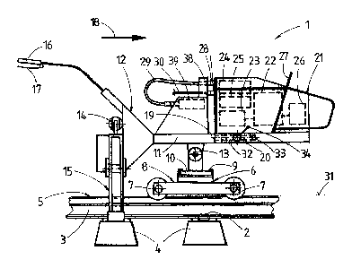
Unité moteur (21) d'une machine (1) pouvant être poussée à la main sur un rail, dotée de poignées (27) et raccordée à une unité de travail (12) au moyen d'un dispositif d'accouplement (20) libérable. L'unité moteur (21) comprend un moteur (22), une pompe hydraulique (23), un réservoir hydraulique (24), un radiateur (25) et un générateur électrique (26). Entre l'unité moteur et l'unité de travail (21, 12) sont disposés des raccordements de conduites (28) pour relier de manière libérable des conduites hydrauliques (29) prévues pour l'alimentation des outils de travail (15) et une conduite de commande du moteur (30).


Abrégé anglais


A motor unit (21) of a machine (1) mobile manually on a track is equipped with
hand grips (27) and connected by means of a detachable coupling (20) to a work
unit (12). The motor unit (21) is composed of a motor (22), a hydraulic pump
(23),
a hydraulic tank (24), a cooler (25), and an electric generator (26). Arranged
between the motor- and work unit (21, 12) are line couplings (28) for
detachable
connection of hydraulic lines (29), provided for actuation of working tools
(15),
and of a motor control line (30).

Revendications

Note : Les revendications sont présentées dans la langue officielle dans laquelle elles ont été soumises.


6
We claim:
1. A manually displaceable machine (1) for track maintenance, comprising a
work unit (12) having two handle grips (16) and working tools (15) designed to
be
actuated by drives (14), and a motor unit (21) joined to the work unit (12)
and
serving for energy supply, wherein the work unit (12) and the motor unit (21)
are
connected by means of an articulated connection (13) to a chassis frame (6)
provided for riding on rails (3) of a track (5) and having flanged rollers
(7),
wherein,
a) the motor unit (21) is equipped with hand grips (27) and connected to the
work
unit (12) by means of a detachable coupling (20);
b) the motor unit (21) is composed of a motor (22), a hydraulic pump (23), a
hydraulic tank (24), a cooler (25), and an electric generator (26);
c) arranged between the motor unit (21) and work unit (12) are line couplings
(28)
for detachable connection of hydraulic lines (29), provided for actuation of
the
working tools (15), and of a motor control line (30).
2. A machine according to claim 1, characterized in that the detachable
coupling (20) provided for connection of the motor unit (21) and the work unit
(12)
is formed by two coupling pins (32) connected to the work unit (12) and
extending
parallel to one another and approximately parallel to a travelling plane (31)
formed by the flanged rollers (7), and by coupling sleeves (33) serving for
housing said coupling pins (32) and connected to the motor unit (21), and by a
fixing device (34).
3. A machine according to claim 2, characterized in that the motor unit
(21)
has a first frame (35) connected to the motor (22), and a second frame (36)

7
connected to the coupling sleeves (33), wherein the first and second frames
(35,
36) are connected to one another by damping elements (37).
4. A machine according to claim 2 or claim 3, characterized in that the
line
couplings (28) comprise a coupling block (38) connected to the motor unit (21)
and to the work unit (12), for an automatic coupling operation of the
hydraulic
lines (29) and motor control lines (30) by pushing the motor unit (21) onto
the
coupling pins (32).
5. A machine according to any one of claims 1 to 4, characterized in that a
valve control (30) provided for controlling the working tools (15) is arranged
on
the work unit (12).

Description

Note : Les descriptions sont présentées dans la langue officielle dans laquelle elles ont été soumises.


I
Manually Displaceable Machine for Maintaining a Track
SCOPE OF THE INVENTION
[01] The invention relates to a manually displaceable machine for track
maintenance, consisting of a work unit having two hand grips and
working tools designed to be actuated by drives, and a motor unit
joined to the work unit and serving for energy supply, wherein the
work- and motor unit is connected by means of an articulated
connection to a chassis frame provided for riding on rails of a track and
having flanged rollers.
BACKGROUND OF THE INVENTION
[02] A machine of this type is known from FR 2 659 674 or DE 20305569
U1, wherein the working tools are used for installing rail clips. During
working operations, the machine is displaced on the track to the next
sleeper by means of the hand grips. Since such machines are
relatively heavy, the removal thereof from the track or the transferring
to the track poses a physical burden on the operating personnel
reaching the acceptable limits.
SUMMARY OF THE INVENTION
[03] It is the object of the present invention to provide a machine of the
type
mentioned at the beginning with which a simplified transfer into the
working position or removal from the track is made possible.
[04] According to the invention, this object is achieved with a machine of
the specified kind having one or more features described herein.
CA 2878760 2019-05-15

2
[05] Owing to these features, it is possible to transport the motor unit
and
the work unit separately and reconnect them to one another again very
simply, as required, meaning a significant relief of physical strain for
the operating personnel. In an advantageous manner, projecting parts
of the coupling can be used as hand grips for transporting the work
unit. Additionally, for versatile use, the motor unit can also be coupled
as energy supply to different work units designed for various functions.
[05a] Accordingly, in one aspect the present invention resides in a manually
displaceable machine for track maintenance, comprising a work unit
having two handle grips and working tools designed to be actuated by
drives, and a motor unit joined to the work unit and serving for energy
supply, wherein the work unit and the motor unit are connected by
means of an articulated connection to a chassis frame provided for
riding on rails of a track and having flanged rollers, wherein, a) the
motor unit is equipped with hand grips and connected to the work unit
by means of a detachable coupling; b) the motor unit is composed of a
motor, a hydraulic pump, a hydraulic tank, a cooler, and an electric
generator; c) arranged between the motor unit and work unit are line
couplings for detachable connection of hydraulic lines, provided for
actuation of the working tools, and of a motor control line.
[06] Additional advantages of the invention become apparent from the
following specification and the drawing description.
BRIEF DESCRIPTION OF THE DRAWINGS
[07] The invention will be described in more detail below with reference to
an embodiment represented in the drawing in which Figs. 1 and 2 each
CA 2878760 2019-05-15

2a
show a side view of a machine for track maintenance, Fig. 3 shows an
enlarged detail view, and Fig. 4 shows a top view of the machine.
DETAILED DESCRIPTION OF THE PREFERRED EMBODIMENTS
[08] A machine 1, shown in Fig. 1, is designed for installing rail
clips 2 by
means of which rails 3 and sleepers 4 of a track 5 are connected to
one another. The machine 1 has a chassis frame 6 which is supported
and able to roll on both rails 3 by means of a respective undercarriage
8 equipped with flange rollers 7. A transverse guide 9 extending in the
transverse direction of the track connects the two undercarriages 8 to
one another and serves for the transversely displaceable support of a
carriage 10.
CA 2878760 2019-05-15

CA 02878760 2015-01-09
3
[09] Mounted on said carriage 10 is an assembly frame 11 of a work unit
12, said frame extending in the longitudinal direction of the track or
rails and being designed to be rotatable or tiltable relative to the
chassis frame 6 by means of an articulated connection 13 and to be
positioned by means of the transverse guide 9 above one or the other
rail 3 of the track 5, as desired (see Fig. 4).
[10] The assembly frame 11 is connected at its one end, distanced from the
articulated connection 13, to working tools 15 actuatable by drives 14
and to two hand grips 16 having control elements 17. A front end 19 ¨
with regard to a displacement direction 18 of the machine 1 ¨ of the
work unit 12 is connected by means of a coupling 20 to a motor unit 21.
[11] The motor unit 21 is composed of a motor 22, a hydraulic pump 23, a
hydraulic tank 24, a cooler 25, and an electric generator 26 with an
alternator and can be transported by means of hand grips 27 (see Fig.
2). Arranged between the motor- and work unit (21, 12) are line
couplings 28 for releasable connection of hydraulic lines 29, provided
for actuation of the drives 14, and of a motor control line 30.
[12] The coupling 20 provided for connection of the motor- and work unit
21, 12 is formed, on the one hand, by two coupling pins 32, connected
to the work unit 12 and extending parallel to one another and
approximately parallel to a travelling plane 31 formed by the flanged
rollers 7 or rails 3, and, on the other hand, by coupling sleeves 33

CA 02878760 2015-01-09
4
connected to the motor unit 21 and serving for housing the coupling
pins 32, and also by a fixing device 34.
[13] As visible in Fig. 3, the motor unit 21 has a first frame 35 connected
to
the motor 22, and a second frame 36 connected to the coupling
sleeves 33. The two frames 35, 36, positioned one above the other,
are connected to one another solely by damping elements 37.
[14] The line couplings 28 are designed as a coupling block 38 connected,
on the one hand, to the motor unit 21 and, on the other hand, to the
work unit 12, for a coupling operation of the hydraulic- and motor
control lines 29, 30 occurring automatically by pushing the motor unit
21 onto the coupling pins 32. A valve control 30 provided for controlling
the working tools 15 is arranged on the work unit 12. Alternatively,
instead of the automatic coupling, it would also be possible to carry out
a coupling operation manually.
[15] For working operations of the machine 1, the chassis frame 6 is first
placed upon the rails 3. Subsequently, the work unit 12 ¨ by grabbing
the hand grips 16, on the one hand, and the coupling pins 32, on the
other hand ¨ can be carried effortlessly and fixed onto the articulated
connection 13. Finally, the motor unit 21 is gripped with the aid of the
hand grips 27, pushed onto the coupling pins 32, and fixed by means
of the fixing device 34. As a result of the pushing motion, the hydraulic-
and motor control lines 29, 30 are coupled automatically, whereby the

CA 02878760 2015-01-09
machine 1 is fully assembled and operational. The removal of the
machine 1 from the track 5 can likewise be accomplished in three parts
in that first the motor unit 21 is pulled from the coupling pins 32. In
further sequence, the work unit 12 is separated from the chassis frame
6 and transported away.

Dessin représentatif
Une figure unique qui représente un dessin illustrant l'invention.
États administratifs

2024-08-01 : Dans le cadre de la transition vers les Brevets de nouvelle génération (BNG), la base de données sur les brevets canadiens (BDBC) contient désormais un Historique d'événement plus détaillé, qui reproduit le Journal des événements de notre nouvelle solution interne.

Veuillez noter que les événements débutant par « Inactive : » se réfèrent à des événements qui ne sont plus utilisés dans notre nouvelle solution interne.

Pour une meilleure compréhension de l'état de la demande ou brevet qui figure sur cette page, la rubrique Mise en garde , et les descriptions de Brevet , Historique d'événement , Taxes périodiques et Historique des paiements devraient être consultées.

Historique d'événement

Description Date
Le délai pour l'annulation est expiré 2023-01-26
Lettre envoyée 2022-07-25
Lettre envoyée 2022-01-26
Lettre envoyée 2021-07-26
Représentant commun nommé 2019-10-30
Accordé par délivrance 2019-10-22
Inactive : Page couverture publiée 2019-10-21
Préoctroi 2019-08-29
Inactive : Taxe finale reçue 2019-08-29
Un avis d'acceptation est envoyé 2019-07-29
Lettre envoyée 2019-07-29
month 2019-07-29
Un avis d'acceptation est envoyé 2019-07-29
Inactive : Approuvée aux fins d'acceptation (AFA) 2019-07-22
Inactive : Q2 réussi 2019-07-22
Requête visant le maintien en état reçue 2019-06-14
Modification reçue - modification volontaire 2019-05-15
Inactive : Dem. de l'examinateur par.30(2) Règles 2019-01-07
Inactive : Rapport - Aucun CQ 2019-01-03
Lettre envoyée 2018-11-15
Requête visant le maintien en état reçue 2018-11-05
Exigences de rétablissement - réputé conforme pour tous les motifs d'abandon 2018-11-05
Réputée abandonnée - omission de répondre à un avis sur les taxes pour le maintien en état 2018-07-25
Lettre envoyée 2018-03-16
Requête d'examen reçue 2018-03-05
Exigences pour une requête d'examen - jugée conforme 2018-03-05
Toutes les exigences pour l'examen - jugée conforme 2018-03-05
Requête visant le maintien en état reçue 2017-06-13
Requête visant le maintien en état reçue 2016-06-06
Requête visant le maintien en état reçue 2015-06-19
Demande de correction du demandeur reçue 2015-02-24
Inactive : Page couverture publiée 2015-02-20
Lettre envoyée 2015-02-06
Inactive : Transfert individuel 2015-01-26
Inactive : Notice - Entrée phase nat. - Pas de RE 2015-01-26
Inactive : CIB en 1re position 2015-01-23
Inactive : CIB attribuée 2015-01-23
Demande reçue - PCT 2015-01-23
Exigences pour l'entrée dans la phase nationale - jugée conforme 2015-01-09
Demande publiée (accessible au public) 2014-02-20

Historique d'abandonnement

Date d'abandonnement Raison Date de rétablissement
2018-07-25

Taxes périodiques

Le dernier paiement a été reçu le 2019-06-14

Avis : Si le paiement en totalité n'a pas été reçu au plus tard à la date indiquée, une taxe supplémentaire peut être imposée, soit une des taxes suivantes :

  • taxe de rétablissement ;
  • taxe pour paiement en souffrance ; ou
  • taxe additionnelle pour le renversement d'une péremption réputée.

Les taxes sur les brevets sont ajustées au 1er janvier de chaque année. Les montants ci-dessus sont les montants actuels s'ils sont reçus au plus tard le 31 décembre de l'année en cours.
Veuillez vous référer à la page web des taxes sur les brevets de l'OPIC pour voir tous les montants actuels des taxes.

Historique des taxes

Type de taxes Anniversaire Échéance Date payée
Taxe nationale de base - générale 2015-01-09
Enregistrement d'un document 2015-01-26
TM (demande, 2e anniv.) - générale 02 2015-07-27 2015-06-19
TM (demande, 3e anniv.) - générale 03 2016-07-25 2016-06-06
TM (demande, 4e anniv.) - générale 04 2017-07-25 2017-06-13
Requête d'examen - générale 2018-03-05
Rétablissement 2018-11-05
TM (demande, 5e anniv.) - générale 05 2018-07-25 2018-11-05
TM (demande, 6e anniv.) - générale 06 2019-07-25 2019-06-14
Taxe finale - générale 2019-08-29
TM (brevet, 7e anniv.) - générale 2020-07-27 2020-07-15
Titulaires au dossier

Les titulaires actuels et antérieures au dossier sont affichés en ordre alphabétique.

Titulaires actuels au dossier
ROBEL BAHNBAUMASCHINEN GMBH
Titulaires antérieures au dossier
OTTO WIDLROITHER
Les propriétaires antérieurs qui ne figurent pas dans la liste des « Propriétaires au dossier » apparaîtront dans d'autres documents au dossier.
Documents

Pour visionner les fichiers sélectionnés, entrer le code reCAPTCHA :


Pour visualiser une image, cliquer sur un lien dans la colonne description du document (Temporairement non-disponible). Pour télécharger l'image (les images), cliquer l'une ou plusieurs cases à cocher dans la première colonne et ensuite cliquer sur le bouton "Télécharger sélection en format PDF (archive Zip)" ou le bouton "Télécharger sélection (en un fichier PDF fusionné)".

Liste des documents de brevet publiés et non publiés sur la BDBC .

Si vous avez des difficultés à accéder au contenu, veuillez communiquer avec le Centre de services à la clientèle au 1-866-997-1936, ou envoyer un courriel au Centre de service à la clientèle de l'OPIC.

({010=Tous les documents, 020=Au moment du dépôt, 030=Au moment de la mise à la disponibilité du public, 040=À la délivrance, 050=Examen, 060=Correspondance reçue, 070=Divers, 080=Correspondance envoyée, 090=Paiement})


Description du
Document 
Date
(aaaa-mm-jj) 
Nombre de pages   Taille de l'image (Ko) 
Abrégé 2015-01-08 1 13
Description 2015-01-08 5 144
Revendications 2015-01-08 2 55
Dessins 2015-01-08 2 40
Dessin représentatif 2015-01-08 1 19
Description 2019-05-14 6 164
Revendications 2019-05-14 2 50
Abrégé 2019-07-28 1 14
Dessin représentatif 2019-09-29 1 16
Avis d'entree dans la phase nationale 2015-01-25 1 205
Courtoisie - Certificat d'enregistrement (document(s) connexe(s)) 2015-02-05 1 125
Rappel de taxe de maintien due 2015-03-25 1 110
Courtoisie - Lettre d'abandon (taxe de maintien en état) 2018-09-04 1 174
Avis de retablissement 2018-11-14 1 165
Accusé de réception de la requête d'examen 2018-03-15 1 175
Avis du commissaire - Demande jugée acceptable 2019-07-28 1 162
Avis du commissaire - Non-paiement de la taxe pour le maintien en état des droits conférés par un brevet 2021-09-06 1 554
Courtoisie - Brevet réputé périmé 2022-02-22 1 538
Avis du commissaire - Non-paiement de la taxe pour le maintien en état des droits conférés par un brevet 2022-09-05 1 540
Paiement de taxe périodique 2018-11-04 1 66
PCT 2015-01-08 4 143
Correspondance 2015-01-25 4 122
Correspondance 2015-02-23 2 79
Paiement de taxe périodique 2015-06-18 1 56
Paiement de taxe périodique 2016-06-05 1 52
Paiement de taxe périodique 2017-06-12 1 52
Requête d'examen 2018-03-04 1 56
Demande de l'examinateur 2019-01-06 3 188
Modification / réponse à un rapport 2019-05-14 11 323
Paiement de taxe périodique 2019-06-13 1 51
Taxe finale 2019-08-28 1 57