Sélection de la langue

Search

Sommaire du brevet 2879062 

Énoncé de désistement de responsabilité concernant l'information provenant de tiers

Une partie des informations de ce site Web a été fournie par des sources externes. Le gouvernement du Canada n'assume aucune responsabilité concernant la précision, l'actualité ou la fiabilité des informations fournies par les sources externes. Les utilisateurs qui désirent employer cette information devraient consulter directement la source des informations. Le contenu fourni par les sources externes n'est pas assujetti aux exigences sur les langues officielles, la protection des renseignements personnels et l'accessibilité.

Disponibilité de l'Abrégé et des Revendications

L'apparition de différences dans le texte et l'image des Revendications et de l'Abrégé dépend du moment auquel le document est publié. Les textes des Revendications et de l'Abrégé sont affichés :

  • lorsque la demande peut être examinée par le public;
  • lorsque le brevet est émis (délivrance).
(12) Demande de brevet: (11) CA 2879062
(54) Titre français: TUBE SUPERIEUR D'ENDOSCOPE POUR INSERTION DANS UN ORIFICE NATUREL DU CORPS
(54) Titre anglais: ENDOSCOPE OVERTUBE FOR NATURAL BODY ORIFICE INSERTION
Statut: Réputée abandonnée et au-delà du délai pour le rétablissement - en attente de la réponse à l’avis de communication rejetée
Données bibliographiques
(51) Classification internationale des brevets (CIB):
  • A61B 01/273 (2006.01)
  • A61B 01/00 (2006.01)
  • A61B 01/24 (2006.01)
  • A61B 01/31 (2006.01)
(72) Inventeurs :
  • WEST, STEPHEN (Etats-Unis d'Amérique)
(73) Titulaires :
  • APOLLO ENDOSURGERY, INC.
(71) Demandeurs :
  • APOLLO ENDOSURGERY, INC. (Etats-Unis d'Amérique)
(74) Agent: MLT AIKINS LLP
(74) Co-agent:
(45) Délivré:
(86) Date de dépôt PCT: 2013-07-10
(87) Mise à la disponibilité du public: 2014-01-23
Requête d'examen: 2018-07-09
Licence disponible: S.O.
Cédé au domaine public: S.O.
(25) Langue des documents déposés: Anglais

Traité de coopération en matière de brevets (PCT): Oui
(86) Numéro de la demande PCT: PCT/US2013/049830
(87) Numéro de publication internationale PCT: US2013049830
(85) Entrée nationale: 2015-01-13

(30) Données de priorité de la demande:
Numéro de la demande Pays / territoire Date
13/551,942 (Etats-Unis d'Amérique) 2012-07-18

Abrégés

Abrégé français

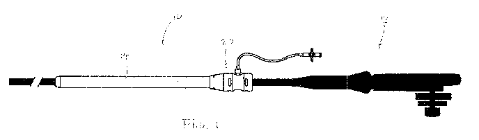
L'invention concerne un tube supérieur d'endoscope, qui comprend un élément tubulaire flexible et un ensemble moyeu prévu sur l'extrémité proximale de l'élément tubulaire. L'ensemble moyeu comprend un poignet d'étanchéité pour manchon élastique, qui s'étend autour de la surface interne d'un élément corporel du moyeu. Les extrémités du poignet d'étanchéité sont couplées à l'élément corporel. Une ligne de gonflage s'étend dans l'élément corporel, en communication avec la surface externe du poignet d'étanchéité. Lorsque le fluide est mis sous pression par la ligne de gonflage, le poignet est détendu vers l'intérieur, afin de réduire la taille de l'ouverture à travers l'orifice, de sorte que le poignet forme un joint autour d'un endoscope reçu à travers le moyeu. L'élément corporel est de préférence couplé à l'élément tubulaire flexible et au poignet d'étanchéité élastique à l'aide d'un engagement d'enclenchement de pièces, de telle sorte qu'aucune fixation, soudure, colle et autre ne soit nécessaire pour fixer l'ensemble moyeu avec.


Abrégé anglais

An endoscope overtube includes a flexible tubular member and a hub assembly provided at the proximal end of the tubular member. The hub assembly includes an elastic sleeve seal cuff extending about the inner surface of a body member of the hub. The ends of seal cuff are coupled to the body member. An inflation line extends into the body member in communication with the outer surface of the seal cuff. When fluid is pressurized through the inflation line, the cuff is distended inward to reduce the size of the opening through the port such that the cuff forms a seal about an endoscope received through the hub. The body member is preferably coupled to each of the flexible tubular member and to the elastic seal cuff using a snap-fit engagement of parts such that no fasteners, welds, glues, etc. are necessary for securing the hub assembly together.

Revendications

Note : Les revendications sont présentées dans la langue officielle dans laquelle elles ont été soumises.


8
WHAT IS CLAIMED IS:
1. An overtube for use with an endoscope and for insertion through a patient's
natural body
orifice, said overtube comprising:
a) a tubular member having a proximal portion and a distal portion, and a
length therebetween
sufficient to extend from a patient's mouth to a patient's stomach, said
tubular member defining
a central passage for receiving the endoscope therethrough; and
b) a hub assembly coupled to said proximal portion of said tubular member,
said hub assembly
including
a rigid body member having an inner surface defining an interior opening with
a first
diameter, and a fluid connector, and
a flexible sleeve extending within said inner surface of said body member,
said sleeve
having an outer surface, an inner surface, and first and second ends, said
first and second ends
coupled relative to said body member and said outer surface of said sleeve and
said inner
surface of said body member are in communication with said fluid connector,
wherein when a fluid is provided under pressure through said fluid connector,
said
sleeve distends radially inward to define a second diameter smaller than said
first diameter.
2. An overtube according to claim 1, wherein:
when there is no fluid between said outer surface of said sleeve and said
inner surface of
said body member, said outer surface of said sleeve is in contact with said
inner surface of said
body member along substantially an entirety of said central passage, and
when fluid is provided between said outer surface of said sleeve and said
inner surface
of said body member, said outer surface of said sleeve at least along a
longitudinally central
portion of said sleeve is displaced from said inner surface of said body
member.

9
3. An overtube according to claim 1, wherein:
said first and second ends of said sleeve are fixed relative to said body
member.
4. An overtube according to claim 1, wherein:
said first and second ends of said sleeve are provided with respective first
and second O-
rings, and said body member includes first and second ends defining respective
first and second
circumferential grooves, and said first O-ring is received in said first
circumferential groove,
and said second O-ring is received in said second circumferential groove.
5. An overtube according to claim 4, wherein:
said first and second circumferential grooves are located on an exterior
surface of said
body member, and said first end of said sleeve is everted over said first end
of said body
member, and said second end of said sleeve is everted over said second end of
said body
member.
6. An overtube according to claim 5, wherein said hub assembly further
includes a tube collar
assembly coupled at said first end of said body member, said tube collar
assembly coupling said
tubular member relative to said hub assembly, and a hub collar coupled at said
second end of
said body member.
7. An overtube according to claim 6, wherein:
said first O-ring is secured in said first groove by said tube collar
assembly, and said
second O-ring is secured in said second groove by said hub collar.
8. An overtube according to claim 6, wherein:
said tube collar assembly is snap fit to said first end of said body member,
and said hub
collar is snap fit to said second end of said body member.
9. An overtube according to claim 6, wherein:
said tube collar assembly includes an inner collar that partly extends into
said proximal
portion of said tubular member, and an outer collar that extends over said
proximal portion of

10
said tubular member and said inner collar to engage said proximal portion of
said tubular
member between said inner and outer collars, said inner and outer collars
coupled together in a
snap fit engagement.
10. An overtube according to claim 1, wherein:
said body member is longitudinally symmetrical.
11. An overtube according to claim 1, wherein:
said tubular member is reinforced to remain patent and longitudinally stiff
during
insertion into the natural orifice, while remaining sufficiently laterally
flexible for insertion
through a non-straight natural orifice.
12. An overtube according to claim 1, wherein:
said tubular member comprises a polymer reinforced with a metal coil.
13. An overtube according to claim 1, wherein:
said sleeve is elastic.
14. An overtube according to claim 13, wherein:
said sleeve comprises one of polyisoprene and latex.
15. An overtube according to claim 1, in combination with said endoscope,
wherein when said
endoscope extends through said hub assembly and said fluid is provided under
pressure through
said fluid connector, said sleeve distends radially inward to form a seal
about said endoscope.
16. An overtube for use with an endoscope and for insertion through a
patient's natural body
orifice, said overtube comprising:
a) a tubular member having a proximal portion and a distal portion, and a
length therebetween
sufficient to extend from a patient's mouth to a patient's stomach, said
tubular member defining
a central passage for receiving the endoscope therethrough; and
b) a hub assembly coupled to said proximal portion, said hub assembly
including

11
a rigid body member having a first end, a second end, an inner surface
defining a
smooth central passage, and a fluid connector,
a flexible sleeve extending within said central passage of said body member,
said sleeve
having an outer surface, an inner surface, and first and second ends, said
first and second ends
coupled relative to said body member and said outer surface of said sleeve and
said inner
surface of said body member are in communication with said fluid connector,
an inner collar partly extending into said proximal portion of said tubular
member,
an outer collar extending over said proximal portion of said tubular member
and said
inner collar to engage said proximal portion of said tubular body between said
inner and outer
collars, said outer collar further coupled to said first end of said body
member, and
a proximal hub collar defining a proximal mouth through said hub, said hub
collar
coupled to said second end of said body member,
wherein when a fluid is provided under pressure through said fluid connector,
said
sleeve distends radially inward to define an opening smaller than said central
passage.
17. An overtube according to claim 16, wherein:
said outer collar is coupled in a snap-fit engagement to said inner collar,
said inner collar is coupled in a snap-fit engagement to said first end of
said body
member,
said hub collar is coupled in a snap-fit engagement to said second end of said
body
member.
18. An overtube according to claim 17, wherein:
said inner collar includes an external barb that is inserted into said
proximal end of said
tubular member.

12
19. An overtube according to claim 16, wherein:
said inner collar includes a circumferential retaining groove, and said outer
collar
includes catches that engage said retaining groove of said inner collar to
couple said inner and
outer collars in said snap-fit engagement.
20. An overtube according to claim 17, wherein:
said inner collar has a proximal flange including a plurality of radially
displaced
engagement windows, and said first end of said body member includes a
plurality of catch
barbs that engage within said engagement windows to couple said inner collar
and said body
member in a snap-fit engagement.
21. An overtube according to claim 17, wherein:
said hub collar includes a plurality of radially displaced engagement windows,
and said
second end of said body member includes a plurality of catch barbs that engage
within said
engagement windows of said hub collar to couple said hub collar and said body
member in a
snap-fit engagement.
22. An overtube according to claim 16, wherein:
said body member is longitudinally symmetrical.
23. An overtube according to claim 16, wherein:
said tubular member is reinforced to remain patent and longitudinally stiff
during
insertion into the natural orifice, while remaining sufficiently laterally
flexible for insertion
through a non-straight natural orifice.
24. An overtube according to claim 16, in combination with said endoscope,
wherein when said
endoscope extends through said hub assembly and said fluid is provided under
pressure through
said fluid connector, said sleeve distends radially inward to form a seal
about said endoscope.

Description

Note : Les descriptions sont présentées dans la langue officielle dans laquelle elles ont été soumises.


CA 02879062 2015-01-13
WO 2014/014715 PCT/US2013/049830
1
ENDOSCOPE OVERTUBE FOR NATURAL BODY ORIFICE INSERTION
BACKGROUND OF THE INVENTION
1. Field Of The Invention
The present invention relates to surgery. More particularly, the invention
relates to an access
port for providing secure access through a natural body orifice for an
endoscope and related
instruments.
2. State Of The Art
The field of gastrointestinal endoscopy is generally directed to diagnostic
and therapeutic
techniques to observe, modify and remove tissues located in the digestive
tract. Such diagnosis
is often performed with an endoscope that is inserted into the mouth of a
patient, through the
esophagus, and into the stomach. Flexible endoscopic instruments are then
advanced through
one or more working channels of the endoscope to act on tissues within the
stomach.
Depending on the procedure performed, the endoscope can be used in conjunction
with an
overtube. An overtube is a tubular device that facilitates endoscopy by
providing a conduit
through which the endoscope can be advanced. The use of the overtube protects
the
gastrointestinal mucosa from trauma and limits risks of aspiration. This is
particularly
important where access is required to be maintained for repeated withdrawal
and reinsertion of
the endoscope during certain procedures, such as foreign body removal,
multiple biopsy, or
procedures requiring instrument exchange which may occur external the
endoscope or require
withdrawal of the endoscope.
SUMMARY OF THE INVENTION
According to embodiments of the invention, an endoscope overtube is provided
that facilitates
intraluminal access by an endoscope through a natural orifice, such as the
digestive tract. The
overtube generally includes a flexible tubular member, and a hub assembly
provided at the
proximal end of the flexible tube.

CA 02879062 2015-01-13
WO 2014/014715 PCT/US2013/049830
2
The tubular member has a length sufficient to extend from the mouth, through
the alimentary
canal and to the stomach of the patient. The tubular member is laterally
flexible, but reinforced
to remain patent and longitudinally stiff under conditions of use. The tubular
member defines a
central passage for receiving the endoscope, and a resilient and flexible
tapered distal tip
dimensioned to engage the exterior of the endoscope passed within the central
passage.
According to one aspect of the invention, the hub assembly is provided with an
elastic tubular
sleeve-like seal cuff extending about the inner surface of a body member of
the hub. The
proximal and distal ends of seal cuff are coupled in a fluidtight manner to
the body member,
with an outer surface of the seal cuff in opposition to the inner surface of
the body member, and
an inner surface of the seal cuff exposed within the body member. An inflation
line extends
into the body member in communication with the outer surface of the seal cuff
When fluid is
provided under pressure through the inflation line and between the inner
surface of the body
member and outer surface of the cuff, the cuff is distended radially inward
away from the inner
surface of the body member into an expanded configuration that reduces the
size of the opening
through the port. More particularly, when an endoscope is received through the
hub and the
cuff is expanded under pressure, the cuff forms a seal about the endoscope.
According to another aspect of the invention, the body member is coupled to
each of the
flexible tubular member and to the elastic seal cuff using a snap-fit
engagement of parts such
that no fasteners, welds, glues, etc. are necessary for securing the hub
assembly together. More
particularly, the hub assembly includes an inner collar and an outer collar
between which the
proximal end of the flexible tubular member is secured by engagement of the
inner and outer
collars. The hub assembly also includes a proximal end cap that fixes the
proximal end of the
seal cuff relative to the body member by engagement of the cap to the body
member, and the
inner collar engages relative to the distal end of the body member to fix the
distal end of the
sleeve relative to the body member. According to a preferred aspect of the
invention, the body
member is longitudinally symmetrical such that either end of the body member
may be the
proximal end or distal end, thereby aiding assembly.
Additional objects and advantages of the invention will become apparent to
those skilled in the
art upon reference to the detailed description taken in conjunction with the
provided figures.

CA 02879062 2015-01-13
WO 2014/014715 PCT/US2013/049830
3
BRIEF DESCRIPTION OF THE DRAWINGS
Fig. 1 is a side elevation view of an overtube according to the invention,
with an endoscope
shown in silhouette extending through the overtube.
Fig. 2 is a longitudinal section view through the overtube of Fig. 1.
Fig. 3 is an assembly view of the hub of the overtube.
Fig. 4 is a longitudinal section view across line 4-4 in Fig. 3.
Fig. 5 is a side elevation view of the overtube coupled to an inflation
system.
Fig. 6 is illustrates the inflation of the seal cuff of the overtube by the
inflation system.
DETAILED DESCRIPTION OF THE PREFERRED EMBODIMENTS
With reference to the following description, the terms "proximal" and "distal"
are defined in
reference to the hand of a user of the device, with the term "proximal" being
closer to the user's
hand, and the term "distal" being further from the user's hand such as to
often be located
further within a body of the patient during use.
Turning now to Fig. 1, in accord with the invention, an overtube 10 is
provided for facilitating
access, guidance, and intubation of an endoscope 12 and various endoscopic
instruments into a
natural orifice of a patient for intraluminal procedures. The overtube is
particularly intended
for use in various procedures in which it is inserted through the esophagus or
the colonic
passage, but may have other uses such as intravaginal procedures. In addition,
once the
endoscope is inserted into the overtube 10, the overtube can be operated to
provide a seal about
the endoscope 12 that maintains a condition of insufflation within a body
cavity of the patient,
as described in more detail below.
Referring to Fig. 2, the overtube 10 includes an elongate flexible tubular
member 14 having a
proximal end 16 and a distal end 18, and a hub 20 provided at the proximal end
16 of the
tubular member 14. In a preferred embodiment, the tubular member 14 has a
length sufficient
to extend from the mouth, through the alimentary canal and to the stomach of
the patient, e.g.,
approximately 27 cm, however the tubular member can be provided in other
lengths suitable for

CA 02879062 2015-01-13
WO 2014/014715 PCT/US2013/049830
4
a particular procedure and the respective intraluminal passage. The tubular
member 14 defines
a central passage 22 through which the endoscope 12 is received, and includes
a resilient and
flexible distal tip 24 at its distal end 18 that tapers to a close fitting
diameter for the outer
diameter of the endoscope(s) 12 for which the overtube 10 is intended to be
used. By way of
example only, an embodiment of the overtube is designed to accommodate
endoscopes having
an outer diameter between 10 to 14 mm, defines a central tubular passage 22
with a diameter of
17 mm, and has a distal tip 24 that tapers to a diameter of approximately 11
mm. The tubular
member 14 is preferably a polymeric extrusion reinforced with a metal spring
wire coil 26
extending through or along its wall 28 for the length of the extrusion, except
at its distal tip 24
where increased flexibility is desired and at a proximal coupling portion 30.
The tubular
member construction is laterally flexible, but sufficiently reinforced to
remain patent and
longitudinally stiff during insertion into a natural orifice and under
conditions of use. To
accommodate the various diameter endoscopes, while minimizing the gap between
the
diameters of the overtube 10 and endoscope 12 that may potentially trap
tissue, the distal tip 24
is preferably formed of a resilient material having elastic properties and may
be integrally
formed or joined to tubular member 14.
Referring to Figs. 2 through 4, according to one aspect of the invention, the
hub 20 is an
assembly of five components including an inner tube collar 32 and an outer
tube collar 34 that
together engage the proximal coupling portion 30 of the tubular member 14, a
tubular body
member 36 provided with a fluid line connector 38, a sleeve-like sealing cuff
40 extending
through the body member 36, and a hub collar 42 coupled to a proximal end of
the body
member 36. In a preferred assembly of such components, the body member 36 is
coupled to
each of the tubular member 14 and to the sealing cuff 40 using a snap-fit
engagement of inner
and outer tube collars 32, 34 at its distal end, and the hub collar 42 at its
proximal end, such that
no fasteners, welds, glues, etc. are necessary for securing the hub assembly
together, as well as
securing the hub assembly 20 to the tubular member 14.
More particularly, the inner tube collar 32 includes a tubular portion 44
including a barb 46, a
central circumferential retaining groove 48, and a relatively larger diameter
proximal flange 50
including a plurality of radially displaced engagement windows 52. The outer
tube collar 34
includes a distal tubular portion 54 sized to closely receive the proximal
coupling portion 30 of
the flexible tubular member 14, a larger diameter central portion 56 sized to
receive the tubular

CA 02879062 2015-01-13
WO 2014/014715 PCT/US2013/049830
portion 44 of the inner collar 32, and a relatively larger diameter proximal
portion 58 provided
with catches 60 to engage the retaining groove 48 of the inner collar 32 to
mechanically engage
the inner and outer collars 32, 34 relative to each other. In assembly, the
tubular portion 44 of
the inner collar 32 is inserted into the proximal coupling portion 30 of the
tubular member 14
with the barb 46 making positive engagement within the inner surface of the
tubular member.
The outer collar 34 is advanced over the tubular member 14 such that the
tubular portion 14 of
the inner collar 32 extends to the end of the central portion 56 of the outer
collar 34 and the
catches 60 engage the retaining groove 48 to lock the collars 32, 34 together
about the tubular
member 14. The tubular member 14 is locked to the inner and outer collars 32,
34 by the tight
interference fit created and the positive engagement of the barb 46 against
the inner surface of
the tubular member 14 and the outer collar 34 over the outside of the tubular
member.
The body member 36 includes a first end 62 defining a first circumferential
groove 64 and a
first plurality of catch barbs 66, a central portion 68, and a second end 70
defining a second
plurality of catch barbs 72 and a second circumferential groove 74. The
central portion 68 is
preferably concave about its circumference to facilitate manual gripping
thereof The fluid line
connector 38 is preferably in the form of a leur connector and extends
radially outward from the
central portion 68 and communicates with a smooth tubular interior 78 of the
body member 36.
The tubular interior 78 defines a first diameter D1 generally slightly larger
than the diameter of
the central passage 22. In accord with a preferred aspect of the invention,
the body member 36
is longitudinally symmetrical such that either the first or second ends 62, 70
of the body
member 36 may be the proximal or distal end for connection to either the inner
collar 32 and
hub collar 42, as described below, thereby aiding assembly.
The sleeve-like elastic seal cuff 40 extends through the tubular interior 78
of the body member
36 and has ends each defining an 0-ring 82, 84. The seal cuff 40 is preferably
made from
polyisoprene or latex, though other elastic materials may be used. The 0-rings
82, 84 may be
joined to ends of seal cuff 40 or preferably integrally formed by rolling the
ends of the sleeve-
like elastic seal cuff 40. The ends of the seal cuff 40 are everted over the
first and second ends
62, 70 of the body member 36 with the 0-rings 82, 84 seated in first and
second grooves 64, 74,
respectively, as shown in Fig. 4. The first end 62 of the body member 36 is
then inserted into
the flange 50 of the inner collar 32 in sufficient close tolerance such that
first 0-ring 82 of the
seal cuff 40 is locked within groove 64, and such that the first plurality of
catch barbs 66 extend

CA 02879062 2015-01-13
WO 2014/014715 PCT/US2013/049830
6
through engagement windows 52 to lock the body member 36 relative to the inner
collar 32 and
thus relative to the tubular member 14.
The hub collar 42 is a tubular portion defining a plurality of engagement
windows 86, a locking
surface 88, and an inverted portion forming a hub mouth 90. The hub collar 42
is positioned
over the second end 70 of the body member 36 such that the second plurality of
catch barbs 72
extend through the engagement windows 86 to lock the hub collar 42 relative to
the body
member 36, the locking surface 88 abuts the 0-ring 84 to secure it within the
second groove 74,
and the hub mouth defines a proximal entry into the overtube 10.
Turning to Figs. 1 and 5, with the assembled overtube 10, an inflation device
100 may be
coupled to the fluid connector 38 of the hub 20. One exemplar inflation device
100 includes a
syringe 102 for generating fluid pressure, a fluid line 104 for communicating
the fluid pressure
to the fluid connector 38, and a stopcock 106 for maintaining a fluid
pressure. When fluid,
such as air, is provided under pressure from the inflation device 100, the
fluid enters between
the smooth interior 78 of the body member 36 and the outer surface of the seal
cuff 40, causing
radially inward distension of a central portion of the seal cuff within the
body member 36, such
that the seal cuff defines a second hub diameter D2 smaller than the first hub
diameter D1, as
shown in Fig. 6. This creates a seal about an endoscope 12 inserted through
the hub 20 of the
overtube 10 to prevent loss of pressure in the body cavity when insufflation
is used in a surgical
or diagnostic procedure. Once the seal is effected, the stopcock 106 can be
rotated to maintain
the pressure and seal. When it is desired or necessary to remove the endoscope
from the
overtube, e.g., for removing a tissue sample at the end of the endoscope or at
the end of a
procedure, the stopcock 106 is rotated to release the pressure and deactivate
the seal. The
syringe 102 is then preferably operated to withdraw all, or substantially all,
fluid from between
the seal cuff 40 and the body member 36 to allow the endoscope 12 to be freely
removed from
the overtube 10.
There have been described and illustrated herein an overtube for an endoscope
for use through a
natural body orifice such as a mouth. While a particular embodiment of the
invention has been
described, it is not intended that the invention be limited thereto, as it is
intended that the
invention be as broad in scope as the art will allow and that the
specification be read likewise.
Thus, while particular structure for coupling the various elements of the hub
together have been

CA 02879062 2015-01-13
WO 2014/014715 PCT/US2013/049830
7
described, it will be appreciated that other preferably snap-fit engagement
structure can be used
as well. It will therefore be appreciated by those skilled in the art that yet
other modifications
could be made to the provided invention without deviating from its spirit and
scope as claimed.

Dessin représentatif
Une figure unique qui représente un dessin illustrant l'invention.
États administratifs

2024-08-01 : Dans le cadre de la transition vers les Brevets de nouvelle génération (BNG), la base de données sur les brevets canadiens (BDBC) contient désormais un Historique d'événement plus détaillé, qui reproduit le Journal des événements de notre nouvelle solution interne.

Veuillez noter que les événements débutant par « Inactive : » se réfèrent à des événements qui ne sont plus utilisés dans notre nouvelle solution interne.

Pour une meilleure compréhension de l'état de la demande ou brevet qui figure sur cette page, la rubrique Mise en garde , et les descriptions de Brevet , Historique d'événement , Taxes périodiques et Historique des paiements devraient être consultées.

Historique d'événement

Description Date
Inactive : Morte - Taxe finale impayée 2021-08-31
Demande non rétablie avant l'échéance 2021-08-31
Lettre envoyée 2021-07-12
Réputée abandonnée - omission de répondre à un avis sur les taxes pour le maintien en état 2021-03-01
Représentant commun nommé 2020-11-07
Lettre envoyée 2020-08-31
Réputée abandonnée - les conditions pour l'octroi - jugée non conforme 2020-08-31
Inactive : COVID 19 - Délai prolongé 2020-08-19
Inactive : COVID 19 - Délai prolongé 2020-08-06
Inactive : COVID 19 - Délai prolongé 2020-07-16
Inactive : COVID 19 - Délai prolongé 2020-07-02
Un avis d'acceptation est envoyé 2020-04-01
Lettre envoyée 2020-04-01
Un avis d'acceptation est envoyé 2020-04-01
Inactive : Approuvée aux fins d'acceptation (AFA) 2020-03-04
Inactive : Q2 réussi 2020-03-04
Représentant commun nommé 2019-10-30
Modification reçue - modification volontaire 2019-10-09
Requête visant le maintien en état reçue 2019-06-18
Inactive : Dem. de l'examinateur par.30(2) Règles 2019-04-23
Inactive : Rapport - Aucun CQ 2019-04-17
Lettre envoyée 2018-07-11
Requête d'examen reçue 2018-07-09
Toutes les exigences pour l'examen - jugée conforme 2018-07-09
Exigences pour une requête d'examen - jugée conforme 2018-07-09
Requête visant le maintien en état reçue 2018-06-19
Requête visant le maintien en état reçue 2017-06-20
Exigences relatives à la nomination d'un agent - jugée conforme 2016-08-19
Inactive : Lettre officielle 2016-08-19
Exigences relatives à la révocation de la nomination d'un agent - jugée conforme 2016-08-19
Demande visant la nomination d'un agent 2016-06-28
Demande visant la révocation de la nomination d'un agent 2016-06-28
Inactive : Lettre officielle 2016-06-07
Requête visant le maintien en état reçue 2016-04-07
Requête visant le maintien en état reçue 2015-07-03
Inactive : CIB enlevée 2015-03-20
Lettre envoyée 2015-02-25
Inactive : Page couverture publiée 2015-02-24
Inactive : Réponse à l'art.37 Règles - PCT 2015-02-12
Inactive : Transfert individuel 2015-02-12
Inactive : CIB attribuée 2015-01-27
Inactive : CIB en 1re position 2015-01-27
Demande reçue - PCT 2015-01-27
Inactive : Demande sous art.37 Règles - PCT 2015-01-27
Inactive : Notice - Entrée phase nat. - Pas de RE 2015-01-27
Exigences pour l'entrée dans la phase nationale - jugée conforme 2015-01-13
Demande publiée (accessible au public) 2014-01-23

Historique d'abandonnement

Date d'abandonnement Raison Date de rétablissement
2021-03-01
2020-08-31

Taxes périodiques

Le dernier paiement a été reçu le 2019-06-18

Avis : Si le paiement en totalité n'a pas été reçu au plus tard à la date indiquée, une taxe supplémentaire peut être imposée, soit une des taxes suivantes :

  • taxe de rétablissement ;
  • taxe pour paiement en souffrance ; ou
  • taxe additionnelle pour le renversement d'une péremption réputée.

Les taxes sur les brevets sont ajustées au 1er janvier de chaque année. Les montants ci-dessus sont les montants actuels s'ils sont reçus au plus tard le 31 décembre de l'année en cours.
Veuillez vous référer à la page web des taxes sur les brevets de l'OPIC pour voir tous les montants actuels des taxes.

Historique des taxes

Type de taxes Anniversaire Échéance Date payée
Taxe nationale de base - générale 2015-01-13
Enregistrement d'un document 2015-02-12
TM (demande, 2e anniv.) - générale 02 2015-07-10 2015-07-03
TM (demande, 3e anniv.) - générale 03 2016-07-11 2016-04-07
TM (demande, 4e anniv.) - générale 04 2017-07-10 2017-06-20
TM (demande, 5e anniv.) - générale 05 2018-07-10 2018-06-19
Requête d'examen - générale 2018-07-09
TM (demande, 6e anniv.) - générale 06 2019-07-10 2019-06-18
Titulaires au dossier

Les titulaires actuels et antérieures au dossier sont affichés en ordre alphabétique.

Titulaires actuels au dossier
APOLLO ENDOSURGERY, INC.
Titulaires antérieures au dossier
STEPHEN WEST
Les propriétaires antérieurs qui ne figurent pas dans la liste des « Propriétaires au dossier » apparaîtront dans d'autres documents au dossier.
Documents

Pour visionner les fichiers sélectionnés, entrer le code reCAPTCHA :


Pour visualiser une image, cliquer sur un lien dans la colonne description du document (Temporairement non-disponible). Pour télécharger l'image (les images), cliquer l'une ou plusieurs cases à cocher dans la première colonne et ensuite cliquer sur le bouton "Télécharger sélection en format PDF (archive Zip)" ou le bouton "Télécharger sélection (en un fichier PDF fusionné)".

Liste des documents de brevet publiés et non publiés sur la BDBC .

Si vous avez des difficultés à accéder au contenu, veuillez communiquer avec le Centre de services à la clientèle au 1-866-997-1936, ou envoyer un courriel au Centre de service à la clientèle de l'OPIC.

({010=Tous les documents, 020=Au moment du dépôt, 030=Au moment de la mise à la disponibilité du public, 040=À la délivrance, 050=Examen, 060=Correspondance reçue, 070=Divers, 080=Correspondance envoyée, 090=Paiement})


Description du
Document 
Date
(aaaa-mm-jj) 
Nombre de pages   Taille de l'image (Ko) 
Description 2015-01-12 7 345
Dessin représentatif 2015-01-12 1 9
Revendications 2015-01-12 5 195
Dessins 2015-01-12 3 100
Abrégé 2015-01-12 1 64
Revendications 2019-10-08 3 84
Avis d'entree dans la phase nationale 2015-01-26 1 205
Rappel de taxe de maintien due 2015-03-10 1 111
Courtoisie - Certificat d'enregistrement (document(s) connexe(s)) 2015-02-24 1 103
Rappel - requête d'examen 2018-03-12 1 117
Accusé de réception de la requête d'examen 2018-07-10 1 187
Avis du commissaire - Demande jugée acceptable 2020-03-31 1 550
Avis du commissaire - non-paiement de la taxe de maintien en état pour une demande de brevet 2020-10-12 1 537
Courtoisie - Lettre d'abandon (AA) 2020-10-25 1 547
Courtoisie - Lettre d'abandon (taxe de maintien en état) 2021-03-21 1 553
Avis du commissaire - non-paiement de la taxe de maintien en état pour une demande de brevet 2021-08-22 1 561
PCT 2015-01-12 1 59
Correspondance 2015-01-26 1 22
Correspondance 2015-02-11 3 79
Paiement de taxe périodique 2015-07-02 3 126
Paiement de taxe périodique 2016-04-06 3 131
Requête de nomination d'un agent 2016-06-06 1 36
Courtoisie - Lettre du bureau 2016-06-06 2 50
Correspondance 2016-06-27 2 80
Courtoisie - Lettre du bureau 2016-08-18 1 23
Courtoisie - Lettre du bureau 2016-08-18 1 22
Paiement de taxe périodique 2017-06-19 2 50
Paiement de taxe périodique 2018-06-18 3 106
Requête d'examen 2018-07-08 2 44
Demande de l'examinateur 2019-04-22 5 293
Paiement de taxe périodique 2019-06-17 3 105
Modification / réponse à un rapport 2019-10-08 5 174