Note : Les descriptions sont présentées dans la langue officielle dans laquelle elles ont été soumises.
CA 02879479 2015-01-16
WO 2014/016404 PCT/EP2013/065788
10 Cooling of a Dewar vessel with ice free coolant and for short sample
access
FIELD OF THE INVENTION
The present invention relates a Dewar vessel. In particular, the present
invention relates to a
pump for pumping a coolant for a Dewar vessel and to a Dewar vessel for
storing samples in
a coolant. Furthermore, the invention relates to a method for producing a pump
for pumping
a coolant for a Dewar vessel and to a method for producing a Dewar vessel for
storing
samples in a coolant.
BACKGROUND OF THE INVENTION
Dewar vessels, also denoted as Dewar flasks, are containers designed to
provide a good
thermal insulation. On the one hand, Dewar vessels are used as Thermos bottles
for keeping
beverages hot. On the other hand, Dewar vessels may be employed in
laboratories to keep
samples cool.
Usually, the samples have to be stored at or near the bottom of the Dewar
vessel to provide
an optimal cooling and to ensure that the sample is covered by a coolant such
as liquid
nitrogen. This may complicate the handling of the samples and make a high
throughput
access difficult.
Furthermore, to prevent ice contamination of the coolant by the water vapour
contained in
the ambient air Dewars are usually closed by a lid. High throughput sample
access then
requires opening the Dewar frequently, thus resulting in ice contamination of
the coolant.
- 2 -
SUMMARY OF THE INVENTION
Thus, there may be a need for a possibility to provide a reliable cooling of
samples and at
the same time to provide an easy access to the samples, as well as for a
possibility to keep
the Dewar open while minimizing the amount of ice in the coolant.
According to a first aspect of the present invention a pump for pumping a
coolant in a
Dewar vessel is provided. The pump comprises a chamber, a closing element and
a pressure
increasing device. The chamber comprises an inlet and an outlet and is adapted
to fill
automatically by gravity flow through the inlet. Therein, the inlet of the
chamber is
connectable to a coolant reservoir of the Dewar vessel and the outlet of the
chamber is
connectable to a sample vessel of the Dewar vessel. The closing element is
adapted to
automatically close the chamber by floating when the chamber is filled by
coolant.
Additionally or alternatively the closing element may close the inlet
automatically due to a
stepwise pressure increase inside the'chamber produced by the pressure
increasing device.
Furthermore, the pressure increasing device is adapted to increase the
pressure within the
chamber after the chamber is partly or totally filled with the coolant, and
until part of or all
of the fluid is released through the outlet.
In other words, the idea of the present invention according to the first
aspect is based on
providing a mechanically simple pump for a Dewar vessel which contains no
complicated
moving mechanical parts and operates simply, i.e. the pump may be called
pseudo static.
Due to the simple design and functionality of the pump it may be integrated
directly into the
Dewar vessel and does not require a lot of maintenance or service. The pump
may provide
the required amount of coolant such as liquid nitrogen to an upper part of a
Dewar vessel
such that samples may be stored near an opening at the top of the Dewar vessel
and still be
CA 2879479 2019-12-12
CA 02879479 2015-01-16
WO 2014/016404 PCT/EP2013/065788
- 3 -
sufficiently immersed into the coolant. Therein, the coolant may be set to a
constant level in
the Dewar, in particular a sample vessel of the Dewar. Furthermore, the
coolant may be
recycled and cleaned internally.
Advantageously, due to the simple construction of the pump, it does not
require excessive
connections to the outside of the Dewar vessel. For example, the pump may be
connected to
the external world only by way of a few electrical wires or by a single
pneumatic line.
Furthermore, the pump may have a pseudo volumetric operation. I.e. the amount
of coolant
delivered or conveyed with one operational cycle of the pump into the region
of the samples
is essentially constant over the cycles. This amount may correspond to the
volume of the
chamber of the pump, or may be smaller. Therein, the amount of the coolant
conveyed to the
samples, i.e. to the sample vessel may e.g. be controlled by an amount of heat
delivered to
the coolant within the pump or by a volume of gas injected into the chamber of
the pump, as
explained in detail below.
Moreover, due to the simple design of the pump its size may be easily varied
and adapted to
the requirements of each respective Dewar vessel. A further advantage of the
pump is that it
possibly may be produced at low cost.
Therein, the pump pumps the coolant within the Dewar vessel. Thus, the coolant
is not
pumped to an external location as in known applications, but is recirculated
within the
Dewar vessel. Particularly, the coolant is provided to an upper part of a
Dewar vessel such
that samples may be stored near an opening at the top of the Dewar vessel and
still be
sufficiently immersed into the coolant.
The chamber of the pump may comprise a predefined volume with a housing. The
housing
may comprise materials such as metal and/or synthetic material. The inlet may
for example
be provided at an upper part or at the top of the chamber. This may enhance
the filling of the
chamber by gravity flow and make possible the operation of the closing
element. The outlet
CA 02879479 2015-01-16
WO 2014/016404 PCT/EP2013/065788
- 4 -
may be provided at a lower part or at the bottom of the chamber.
Alternatively, the outlet
may be provided in a side wall or at the top the chamber. Preferably, the
inlet is provided at
the top of the chamber such that the coolant flows downwards by gravity into
the chamber.
In this case the chamber may fill faster as compared to when the inlet is
provided at the
bottom of the chamber and the coolant has to flow into the chamber against the
hydrostatic
pressure of the fluid already present in the chamber. Particularly, with an
inlet at the bottom
of the chamber the chamber may not fill at all if the gas within the chamber
is not evacuated
or, e.g. has no way of leaving the chamber. In addition to providing the inlet
at the top of the
chamber an evacuating device may be incorporated into the inlet or into a
valve provided at
the inlet. This may enhance a proper and fast evacuation of the gas.
The pump is designed for placement within a Dewar vessel, in particular,
within a coolant
reservoir of a Dewar vessel. Therein, the coolant may for example be liquid
nitrogen. The
inlet of the chamber may be connected to the coolant reservoir and the outlet
of the chamber
may be connected to a sample vessel of the Dewar vessel.
The closing element may be designed as a floating element (i) or for example
as a large
surface non-return valve (ii). The closing element may be normally opened e.g.
by gravity in
case of a floating element (i) or by a low force spring in case of a non-
return valve (ii).
Furthermore, the closing element may be closed by a fast pressure increase in
the chamber
created by the pressure increasing device.
When the pump is empty the inlet is open in case of the floating element (i)
because it is not
floating. Therein, the floating element comprises a material which has a lower
density as the
coolant. Particularly, the closing element is made of a material which has a
lower density
than liquid nitrogen, such that it swims on top of the liquid nitrogen when it
is filled into the
chamber. Furthermore, if the closing element is designed as a non-return valve
(ii), the inlet
is kept open by gravity or by the low force spring. A guiding rail or guiding
rod may be
provided within the chamber for guiding the closing element. I.e. the
movability of the
closing element may be restricted to one dimension within the chamber. For
example the
CA 02879479 2015-01-16
WO 2014/016404 PCT/EP2013/065788
- 5 -
closing element may move along the guiding rod from the bottom of the chamber
to the inlet
of the chamber.
When the pump is positioned within the coolant or immersed at least partially
into the
coolant within the Dewar vessel, the chamber fills automatically with coolant
due to gravity.
Therein, the pump is positioned within the coolant in such a way that the
inlet is immersed
into the coolant. The closing element floats at the top of the coolant and
closes the inlet
when the chamber is filled in case of a design as a floating element (i).
Alternatively, the
closing element closes when a fast pressure increase in the chamber is created
by the
pressure increasing device in case of a design as a non-return valve (ii).
Thus, the closing
element closes automatically when the chamber is filled with coolant, i.e. the
closing
functionality of the closing element only directly depends on the fill level
of the chamber
and is realized as soon as a certain fill level is reached.
According to a further alternative, the closing element may be an active valve
driven by an
electro magnet or driven mechanically. I.e. the closing element may be
actuable by a driving
unit which is electrically connected to the active valve. Furthermore, the
closing element
may be actuated by a mechanical connection, e.g. manually or automatically.
The
mechanical connection may for example be provided from the top of the Dewar
vessel, e.g.
as a rod coupled to the active valve.
After the chamber is filled a pressure increasing device is activated to
increase the pressure
within the chamber. Therein, the pressure increasing device may for example be
adapted to
increase the pressure indirectly by heating or directly by compressing the
content of the
chamber. In particular, the pressure increasing device may be a low thermal
inertia heating
element such as a wire with a high resistance. Alternatively, the pressure
increasing device
may be a gas pump, e.g. a piston pump connected to the chamber via a tube.
The pressure increasing device increases the pressure until it is high enough
to overcome a
restricting element at the outlet of the chamber. Therein, the restricting
element may for
CA 02879479 2015-01-16
WO 2014/016404
PCT/EP2013/065788
- 6 -
example be a non-return valve or a restrictor, e.g. a throttle valve. The
coolant contained in
the chamber is than released or ejected via a line to the sample vessel of the
Dewar vessel.
The pressure is preferably increased in a "flash" such that most of the
coolant is released
from the chamber before the inlet is opened. After the emptying of the
chamber, the closing
element sinks and the inlet opens again such that the pump cycle, also denoted
as "stroke"
may be repeated. The cycle may be repeated continuously such that the sample
vessel of the
Dewar is filled continuously with fresh ice free coolant. This again allows to
position the
sample vessel near an opening of the Dewar vessel where the samples are easily
accessible
for manual transfer and may be manipulated at a high rate by robotized
systems.
According to an embodiment of the present invention the pressure increasing
device is a
resistor which is adapted for heating the coolant to increase the pressure
within the chamber
by evaporating part of the coolant. Particularly, the resistor may be a
resistive wire, i.e. a
wire with a high resistance in which a part of the electric energy provided to
the wire is
transformed into heat. The resistor may be designed to have a large surface.
For example,
the resistor may be designed with several coils or windings. Furthermore, the
resistor may
comprise a meandering shape.
Therein, the resistor is arranged within the chamber and is in direct contact
with the coolant
within the chamber. Moreover, the resistor is connected to an energy source
such as a
voltage supply. The energy source may be arranged outside the pump and
possibly outside
the Dewar vessel. The resistor may be connected to the energy source by at
least one
electrical line, which e.g. may comprise two wires.
The resistor is supplied with energy after the inlet of the pump is closed by
the closing
element. Therein, closed may denote completely closed or almost closed. If for
example, the
closing element is designed as a floating element, the resistor may be
supplied with energy
after the inlet is actually closed. However, if the closing element is
designed as a non-return
valve with a large surface, the resistor may be supplied with energy after the
fill level in the
chamber reaches a certain level and the non-return valve is in the vicinity of
the inlet. In this
CA 02879479 2015-01-16
WO 2014/016404 PCT/EP2013/065788
- 7 -
case the non-return valve closes the outlet after the pressure is increased,
due to a dynamic
difference of pressure.
The electric energy supplied is transformed into heat at the resistor. The
heat is conveyed
directly to the coolant in the chamber. Part of the coolant evaporates which
leads to a fast
pressure increase which displaces the coolant from the chamber of the pump
into the sample
vessel. Therein, in the case of liquid nitrogen a little amount of evaporated
nitrogen is
enough to create sufficient pressure to open the outlet of the chamber.
According to a further embodiment of the present invention the pressure
increasing device is
a piston pump. The piston pump may be arranged outside the chamber and
possibly outside
the pump and outside the Dewar vessel. Therein, the piston pump is connected
to the
chamber by a small diameter pneumatic tube and can operate at room
temperature. The
piston pump is thus adapted for use with the Edge Dewar described below.
However, the
piston pump may also be replaced by other types of pumps or by a pressurized
gas supplies
in combination with a vane.
According to a further embodiment of the present invention the pressure
increasing device is
a gas supply possibly in combination with a control valve. For example a
Nitrogen gas or
dry air may be supplied to the chamber by the pressure increasing device. The
Nitrogen gas
or dry air supply may be connected to the pump via a control valve. The
Nitrogen gas or the
dry air may be supplied to the chamber at a pressure of about 1 bar.
According to a further embodiment of the present invention the pump further
comprises a
control device which is adapted for activating the pressure increasing device,
independently
from a fill level in the chamber, in predefinable intervals of time. For
example, the
automatic filling of the chamber may take about 10 seconds. And the pressure
increasing
and ejecting of the coolant may take about 5 seconds. Thus, the control device
may activate
the pressure increasing device in intervals of 15 seconds. In this case no
fill level sensors are
necessary. The times necessary for a pump cycle may depend on the volume of
the chamber,
CA 02879479 2015-01-16
WO 2014/016404 PCT/EP2013/065788
- 8 -
the size of the inlet and the volume per stroke. Thus, these times may vary
from a few
seconds to minutes.
According to a further embodiment of the present invention the pump further
comprises a
control device which is adapted for determining a fill level in the chamber.
Therein, the
control device is adapted to activate the pressure increasing device after the
determined fill
level in the chamber reaches a certain predefinable fill level value. The
control device may
for example be a central control unit (CPU) and may be electrically and/or
functionally
connected to the closing element, to a fill level sensor and/or to the
pressure increasing
device. The predefinable or predifined fill level value may for example be
stored on a
memory of the control device.
According to a further embodiment of the present invention the pump further
comprises a
fill level sensor. The fill level sensor may for example be designed as a
contact sensor and
be arranged at or near the inlet of the chamber. For example, the fill level
sensor may be
arranged at the closing element. Therein, the fill level senor is adapted to
determine the fill
level in the chamber and to transmit the fill level to the control device. The
control device
compares the determined value with a predefinable value and activates the
pressure
increasing device as soon as the fill level reaches the predefinable value.
The employment of
fill level sensors may be helpful in optimizing the pumping cycle and/or in
monitoring the
operation of the pump.
An additional sensor located in the overflow e.g. at the upper edge of the
sample vessel may
be employed for monitoring the operation of the pump. The additional sensor or
possibly
several additional sensors may be designed as gas/liquid detectors.
According to a further embodiment of the present invention the pump further
comprises a
non-return valve, also denoted as one way valve, arranged at the outlet of the
chamber. The
non-return valve is adapted to open after a predefined pressure is reached
within the
chamber. The non-return valve may be designed as a ball check valve, a
diaphragm check
CA 02879479 2015-01-16
WO 2014/016404
PCT/EP2013/065788
- 9 -
valve or a tilting disc check valve. The non-return valve may open only to let
coolant flow
from the chamber of the pump to the sample vessel of the Dewar. The employing
of a non-
return valve is advantageous because the volume of tubing upward the non-
return valve
stays full of coolant between two pump strokes, thus making the pump more
efficient.
According to a further embodiment of the present invention the pump further
comprises a
restrictor such as a throttle or a throttle valve. The restrictor is arranged
at the outlet of the
chamber. Therein, the restrictor is adapted to limit the flow of coolant
through the outlet,
facilitating the pressure increase within the chamber. The restrictor allows
for the flow
through the outlet to start immediately when the pressure increases. The
restrictor limits the
flow and makes possible the pressure increase in the chamber. The employing of
a restrictor
or throttle valve is advantageous due to its simplicity, reliability and low
cost .
According to a second aspect of the present invention a Dewar vessel for
storing samples in
a coolant is provided. The Dewar vessel comprises a thermally insulated
reservoir for the
coolant, and a sample vessel arranged in the thermally insulated reservoir.
Therein, the
reservoir is provided separately from the sample vessel. In particular, the
reservoir houses
the sample vessel. The reservoir is connected to the sample vessel in such a
way that the
level of coolant is kept constant in the sample vessel.
In other words the idea of the present invention according to the second
aspect is based on
providing reliable cooling of samples which are arranged near the top or near
an opening of
the Dewar vessel by arranging an additional sample vessel in a coolant
reservoir of the
Dewar vessel and by supplying the sample vessel continuously with coolant from
the
reservoir.
Due to the design of the Dewar vessel it is possible to store samples close to
the surface of
the Dewar vessel and thus to make possible a short and easy access to the
samples while
keeping them at the necessary low temperature. Contrary to this, in common
Dewar vessels
samples have to be stored at the bottom of the reservoir to provide sufficient
cooling.
CA 02879479 2015-01-16
WO 2014/016404 PCT/EP2013/065788
- 10 -
The sample vessel may be placed near the top of the Dewar vessel above the
coolant stored
in the reservoir such that the level of coolant in the reservoir is
independent from the level of
coolant in the sample vessel. Particularly, the level of coolant in the
reservoir is lower than
the level of coolant in the sample vessel. In this way the samples are easily
accessible and at
the same time thermal losses in the reservoir are kept low.
Moreover, as ice-free coolant is permanently supplied to the sample vessel the
samples may
stay in an ice free environment even when manipulated at a high rate. The
sample vessel
may further comprise an overflow, ice draining ports and/or ice draining pipes
for removing
ice coming from new samples or from ambient air through the opening of the
Dewar vessel.
Thus, ice may be removed regularly without the necessity to heat or re-heat
frequently and
dry the Dewar vessel.
A further advantage of the Dewar vessel according to the present invention is
the possibility
to refill the system, i.e. the reservoir, with coolant without affecting the
level of coolant in
the sample vessel. For example, the reservoir may be refilled via a standard
high hysteresis
automatic Dewar refilling system.
The Dewar vessel may be adapted for storing samples such as for example frozen
samples at
an automated macromolecular X-ray crystallography synchrotrons beam line. The
samples
may be stored in a fluid coolant, preferably, in liquid nitrogen.
The Dewar vessel may comprise an outer casing and an inner container which is
denoted as
reservoir. The casing and/or the container may comprise metal and/or synthetic
materials.
Between the outer casing and the reservoir is a vacuum layer which prevents an
exchange of
heat between the reservoir and the surroundings of the Dewar vessel. Thus, the
reservoir is
thermally insulated. Within the reservoir a separate vessel, namely the sample
vessel, is
provided. The sample vessel is arranged in an upper part of the reservoir.
Therein, the
sample vessel may be arranged above the level of coolant in the reservoir or
partially
CA 02879479 2015-01-16
WO 2014/016404
PCT/EP2013/065788
- 11 -
immersed into the coolant. The sample vessel may also comprise metal and/or
synthetic
materials.
The reservoir is connected to the sample vessel in such a way that the level
of coolant is
constant in the sample vessel. I.e. coolant is continuously supplied from the
reservoir to the
sample vessel and overflows to compensate for the part of coolant which for
example boils-
off and to compensate the effect of samples removal. For this purpose, for
example the
pump described above may be employed.
The Dewar vessel may furthermore be provided with an overflow of coolant. I.e.
to keep a
constant level of coolant in the sample vessel, more coolant than necessary is
supplied to the
sample vessel. The excess coolant flows for example over the edge of the
sample vessel
back into the reservoir below. Thus, the Dewar vessel may also be denoted as
an Edge
Dewar vessel.
According to a further embodiment of the present invention the Dewar vessel
further
comprises an opening for accessing the sample vessel. The opening may be
arranged in an
upper part or on top of the Dewar vessel. Therein, the sample vessel is
arranged in the
vicinity of the opening. Furthermore, a cover may be provided to cover the
opening.
According to a further embodiment of the present invention the Dewar vessel
comprises a
pump as described above. The pump is arranged within the reservoir. I.e. the
pump is
immersed into the coolant in the reservoir. Therein, the pump is adapted to
continuously
convey coolant from the reservoir into the sample vessel as described above.
Furthermore,
the outlet of the pump is connected via a line or via a pipe to the sample
vessel. The pipe
may be connected to the sample vessel in a lower or preferably in an upper
region of the
sample vessel.
According to a further embodiment of the present invention the Dewar vessel
further
.. comprises a particle filter for filtering ice. Therein, the filer is
arranged at the inlet of the
CA 02879479 2015-01-16
WO 2014/016404 PCT/EP2013/065788
- 12 -
pump. The filter may have a large surface to allow for filtering by gravity
(low pressure
losses) even when significantly contaminated by ice. The filter ensures that
only ice-free
coolant is supplied to the sample vessel from the reservoir.
Ice may be introduced into the Dewar vessel by new samples or from
contamination by the
ambient air through the opening of the Dewar. From the sample vessel ice may
be removed
via the overflow and ice-draining ports and pipes into the reservoir. The
filter makes sure
that this ice stays in the reservoir and the samples stay in an ice-free
environment. Moreover,
the filter enables an ice-removing without the necessity to heat the Dewar
vessel because the
ice accumulates at the filter and the filter may be exchanged after a certain
period of time.
According to a further embodiment of the present invention the Dewar vessel
further
comprises an ice draining port. The ice draining port is provided at a bottom
of the sample
vessel. Therein, the ice draining port is adapted to release ice accumulated
at the bottom of
the sample vessel into the reservoir. Through this ice draining port ice may
be removed
which has a higher density than the coolant. Ice which has a density lower
than the density
of the coolant may float on the coolant and may be removed automatically by
the overflow
over the edge of the sample vessel. Additionally or alternatively a pipe may
be provided
which comprises a first opening and a second opening. The first opening may be
arranged at
the level of the top of the sample vessel and the second opening may be
arranged at a lower
area, e.g. at the bottom of the sample vessel. High density ice may be drained
out of the
sample vessel by overflow, in the same way floating ice is drained out of the
sample vessel
except that it is driven by the coolant flow through the pipe from the opening
set at the
bottom of the sample vessel to the opening set at the edge of the sample
vessel. The ice
coming from the sample vessel will stay in the Dewar vessel, blocked by the
filter.
According to a further embodiment of the present invention a one way valve,
e.g. a non-
return valve is arranged at the ice draining port. The one way valve is
adapted to open when
a predetermined amount of ice is accumulated at the bottom of the sample
vessel. For
example, the one way valve may open only if a predetermined weight or volume
of ice is
CA 02879479 2015-01-16
WO 2014/016404 PCT/EP2013/065788
- 13 -
present. The valve may be actuated from the top of the Dewar by a pusher or by
an
additional control device. Therein, the valve may be actuated by the control
device at
predetermined intervals of time.
According to a third aspect of the present invention a method for producing a
pump
described above is provided. The method comprises: providing a chamber with an
inlet and
an outlet, which chamber is adapted to fill by gravity through the inlet;
arranging a closing
element in the chamber, which closing element is adapted to automatically
close or almost
close the chamber when it is filled by coolant; connecting a pressure
increasing device to the
chamber or arranging it in the chamber such that the pressure increasing
device is adapted to
increase the pressure within the chamber, after the chamber is closed, until
the fluid is
released through the outlet.
According to a forth aspect of the present invention a method for producing a
Dewar vessel
described above is provided. The method comprises: providing a thermally
insulated
reservoir for a coolant; providing a sample vessel separately from the
thermally insulated
reservoir; arranging the sample vessel within the thermally insulated
reservoir; connecting
the reservoir with the sample vessel in such a way that the level of coolant
is kept constant
in the sample vessel, e.g. via a pump.
It should be noted that while the pump is described as adapted for use with a
Dewar vessel,
it may also be used independently from a Dewar vessel. For example, the pump
may be used
for different fluids than coolants. In this case a piston pump may be used as
the pressure
increasing device. Moreover, while the Dewar vessel is described as adapted
for use with a
pump as described above, the Dewar vessel may be used independently, i.e. with
different
pumps.
Furthermore, it should be noted that features described in connection with the
different
devices and methods may be combined with each other. These and other aspects
of the
CA 02879479 2015-01-16
WO 2014/016404 PCT/EP2013/065788
- 14 -
invention will be apparent from and elucidated with reference to the
embodiments described
hereinafter.
BRIEF DESCRIPTION OF THE DRAWINGS
Exemplary embodiments of the invention will be described in the following with
reference
to the following drawings.
Fig 1 shows a cross section of a Dewar vessel according to an
embodiment of the
invention
Fig. 2A to 2E show cross sections of a pump according to a further embodiment
of the
invention in different stages of a pump operation cycle
Fig. 2F shows a cross section of a further embodiment of the pump
DETAILED DESCRIPTION OF EMBODIMENTS
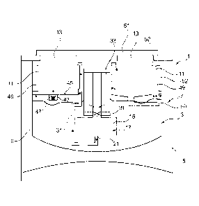
In Fig. 1 a Dewar vessel 1 is presented. The Dewar vessel 1 comprises a
thermally insulated
reservoir 3 for a coolant 9. The reservoir 3 is also denoted as buffer
reservoir. A layer 7 of
vacuum is provided between a casing 5 of the Dewar vessel 1 and the wall of
the reservoir 3.
The layer 7 of vacuum ensures that no heat is transferred between the
environment around
the Dewar vessel 1 and the reservoir 3. Thus, the reservoir 3 and in
particular the coolant 9
within the reservoir 3 is thermally isolated.
Furthermore, a sample vessel 11 is arranged within the reservoir 3. In other
words the
reservoir 3 houses the sample vessel 11. As shown in Fig. 1 the sample vessel
11 is arranged
above the level of coolant 9 in the reservoir 3. However, it is also possible
that the sample
vessel 11 is at least partially immersed into the coolant 9. The sample vessel
11 is adapted to
accommodate and cool e.g. frozen samples. To allow short access and a high
sample
turnover the sample vessel 11 is arranged in the vicinity of or directly at an
opening 13 of
CA 02879479 2015-01-16
WO 2014/016404 PCT/EP2013/065788
- 15 -
the Dewar vessel 13. The opening 13 may be provided with a cover 51. However,
it is also
possible to keep the Dewar vessel 1 according to the invention permanently
open without
significantly affecting the quality of the coolant 9 or the cooling
temperature.
Moreover, the Dewar vessel 1 comprises a pump for automatically and
continuously (in a
pulsed regime) pumping coolant 9 from the reservoir 3 to the sample vessel 11.
The pump
is preferably immersed into the coolant 9 in the reservoir 3 and comprises a
chamber 17
with an inlet 19 and an outlet 21. The inlet 19 is connected to the volume of
the reservoir 3
and the outlet 21 is connected via line 31 to the volume of the sample vessel
11.
10 Furthermore, at the inlet 19 a particle filter 33 is provided. The
filter 33 clears the coolant 9
which enters the pump 15 and subsequently the sample vessel 11 from ice which
may come
from new samples or from ambient air through the opening 13.
The pump 15 continuously injects ice-free coolant 9, particularly liquid
nitrogen, into the
15 sample vessel 11 such that the level of coolant 9 is kept constant in
the sample vessel 11.
The functionality of the pump is described in greater detail below with
reference to Fig. 2.
At the upper edge of the sample vessel 11 an overflow 49 is provided. I.e. the
pump 15
supplies more coolant 9 than necessary to fill the sample vessel 11. Thus, the
excess coolant
.. 9 flows over the edge of the sample vessel 11 back into the reservoir 3.
For this purpose a
pipe may be provided. The overflow 49 may also move ice which floats on the
coolant 9
from the sample vessel 11 to the reservoir 3.
Moreover, at least one ice draining port 43 is provided at the bottom 45 of
the sample vessel
11. This is shown on the left side of the sample vessel 11 in Fig. 1. At the
ice draining port
43 a one-way valve 47 may be provided. The one-way valve 47 may open only at
certain
time intervals or if a certain amount of ice is accumulated on top of the one-
way valve 47.
Additionally or alternatively, a pipe 50 for draining ice may be provided at
the sample vessel
11. This is shown on the right side of the sample vessel 11 in Fig. 1. The
pipe 50 comprises
CA 02879479 2015-01-16
WO 2014/016404 PCT/EP2013/065788
- 16 -
a first opening and a second opening. The bottom 45 of sample vessel 11 may be
designed in
a sloping manner, such that ice with a higher density than coolant 9 moves due
to gravity to
a first opening connected to the lowest point of the bottom 45. The second
opening of the
pipe 50 is arranged at the level of the edge of the sample vessel 11 such that
high density ice
.. may be drained out of the sample vessel 11 by overflow 52 at the second
opening.
The Dewar vessel 1 may be adapted for sample storage at an automated
macromolecular X-
ray crystallography beamline. The sample vessel 11 shown in Fig. 1 comprises a
circular
shape, for example an 0-shape shown in cross section. The filter 33 and the
pump 15 are
arranged in the middle of the circular sample vessel 11. However, different
shapes of the
sample vessel 11 are possible. For example, several separate sample vessels 11
may be
provided within the reservoir 3. Moreover, the pump 15 and the filter 33 may
be arranged
differently within the reservoir 3. For example, the pump 15 and the filter 33
may be
arranged directly at the side wall of the reservoir 3.
Due to the constant level of coolant 9 in the sample vessel lithe Dewar vessel
1 according
to the invention allows samples to be stored close to the surface near the
opening 13. As the
coolant 9 is stored deep within the Dewar vessel 1 below the sample vessel 3
the thermal
losses in the reservoir 3 are kept at a minimum. Moreover, due to the filter
33, the overflow
49 and the ice draining port 43 the samples may stay in an ice free
environment even when
manipulated at a high rate. Furthermore, these components make it possible to
remove ice
from the Dewar vessel 1 without re-heating of the Dewar vessel 1, e.g. by
exchanging the
filter 33 in which the ice is accumulated. The Dewar vessel 1 may also
advantageously
remain permanently open without significantly affecting the quality of the
coolant 9. Finally,
the Dewar vessel 1, and particularly, the reservoir 3 may be refilled with
coolant 9 without
affecting the level of coolant 9 in the sample vessel 11.
In Fig. 2A to 2E different states of operation of the pump 15 are shown. The
pump 15
comprises a chamber 17 immersed in coolant 9. The chamber 17 fills by gravity
and
subsequently ejects the coolant 9 via line 31 into the sample vessel 11. The
sample vessel is
CA 02879479 2015-01-16
WO 2014/016404 PCT/EP2013/065788
- 17 -
shown schematically in Fig. 2A. The pressure for ejecting the coolant 9 from
the chamber 17
is created by evaporation of a part of the coolant 9 situated in the chamber
17 or
alternatively by injecting a volume of gaseous coolant such as gaseous
nitrogen with an
external piston pump 29 as shown in Fig. 2F.
As shown in Fig. 2A the pump 15 is designed as a static pump. I.e. the pump 15
has a simple
design without complicated moving elements. The pump 15 comprises the chamber
17 with
an inlet 19, also denoted as input port, and an outlet 21, also denoted as
output port. In the
embodiment shown, the inlet 19 is arranged at the top of the chamber 17 and
the outlet 21 is
arranged at the bottom of the chamber 17. The outlet 21 is closed by a non-
return valve 39
as shown in Fig. 2A to 2E. Alternatively, as shown in Fig. 2F, the flow from
the outlet 21 is
restricted by a restrictor 41 such as a throttle valve.
The pump 15 further comprises a closing element 23 which e.g. has a lower
density than the
coolant 9 and therefore floats on top of the coolant 9. In Fig. 2 the closing
element 23 is
shown as a floating element. However, the closing element 23 may also be
designed as a
large surface non-return valve possibly with a low force spring connected to
the bottom of
the chamber 17. The closing element 23 may be arranged at a guide or rail
which guides the
closing element 23 to the inlet 19. Moreover, a pressure increasing element 25
is provided
which may increase the pressure within the chamber 17 and in this way to eject
the coolant 9
into the sample vessel 11. In the embodiment shown in Fig. 2A to 2E the
pressure increasing
device 25 is designed as a resistor 27, in particular as a wire with a high
resistance. The
resistor 27 is arranged in the pump 15 in direct contact with the coolant 9
within the
chamber 17. Alternatively, the pressure increasing device 25 is designed as a
piston pump
29 as shown in Fig. 2F. The piston pump 29 may be arranged inside or outside
the Dewar
vessel 1 and may be connected to the chamber 17 via a tube for delivering
gaseous coolant.
Furthermore, a control device 35 connected to the pump is provided in the
Dewar vessel 1.
The control device 35 is shown only schematically in Fig. 2A. The control
device 35 may be
electrically or functionally connected by wires or wirelessly to components of
the pump 15.
CA 02879479 2015-01-16
WO 2014/016404 PCT/EP2013/065788
- 18 -
For example, the control device 35 may be connected to the pressure increasing
device 25 in
order to activate or to actuate the pressure increasing device 25 at the right
moment.
Moreover, the control device 35 may be connected to the non-return valve 39 or
to the
restrictor 41 for opening the access to the sample vessel 11 at the right
moment.
Also, the control device 35 may be connected to a fill level sensor 37. The
fill level sensor
37 may be optionally arranged within the chamber for determining a fill level
of coolant 9 in
the chamber 17. The fill level sensor 37 may be arranged at or in the vicinity
of the inlet 19
as shown in Fig. 2A. Alternatively, the fill level sensor 37 may be included
or integrated into
the closing element 23 as shown in Fig. 2B. Furthermore, the control device 35
may
comprise an energy source or be connected to an energy source. Moreover, the
control
device 35 may comprise a memory on which predefined values e.g. for necessary
fill levels
of the chamber 17 are stored.
In the following the functionality or operation of the pump 15 is explained.
As shown in Fig.
2A, chamber 17 automatically fills by gravity flow through the inlet 19. This
happens during
a thermal equilibrium time, i.e. while the pressure inside and outside the
chamber 17
equilibrate.
As shown in Fig. 2B the closing element 23 closes the inlet 19 as soon as the
chamber 17 is
full with coolant 9 or alternatively if a certain amount of coolant 9 is in
the chamber 17. The
control device 35 (not shown in Fig. 2B) determines or detects that that the
chamber 17 is
filled with coolant 9. This may for example take place by a fill level sensor
or a contact
sensor which transmits a corresponding signal to the control device 35.
Alternatively, the
control device 35 determines that the chamber 17 is filled based on a certain
amount of time
which passed since the last pumping cycle.
Fig. 2C shows the next operational step of the pumping cycle. After the
chamber 17 is filled
with coolant 9 and closed by the closing element 23, the pressure increasing
device 25 is
activated by the control device 35. In the embodiment of Fig. 2C the pressure
increasing
CA 02879479 2015-01-16
WO 2014/016404 PCT/EP2013/065788
- 19 -
device is a resistor 27 which is supplied with electric power via the control
device 35. At the
resistor 27 the electric power is partially transformed into heat and
transferred to the coolant
9 within the closed chamber 17. This results in evaporating of a part of the
coolant 9 in the
chamber 17 which leads to an increase in pressure.
Fig. 2F shows an alternative to the increase of pressure within the chamber
17. According to
the embodiment in Fig. 2F the pressure is increased via a piston pump 29 which
presses
gaseous coolant 9 or any other gaseous substance into the chamber 17. Therein,
the piston
pump 29 may fill with gaseous coolant aspirated from the chamber 17 in an
aspiration
phase.
When the pressure within the chamber 17 reaches a predetermined level the non-
return valve
39 at the outlet 21 of the chamber 17 opens and the coolant 9 is expulsed via
line 31 into the
sample vessel 11. In the alternative embodiment shown in Fig. 2F the non-
return valve 29 is
replaced by a restrictor 41. In a further alternative line 31 may replace the
functionality of a
restrictor 41 by creating sufficient load. In the case of a restrictor 41 flow
of coolant through
the outlet 21 starts immediately when the pressure increases. However, the
restrictor 41
limits the flow and makes possible the pressure increase in the chamber 17.
After the
pressure in the chamber 17 reaches the predetermined value, the coolant 9
flows fast through
the restricted tubing shown in Fig. 2F. The pressure increase is fast enough
for the inlet 19 to
remain closed until most of the coolant 9 is ejected from the outlet 21. In
particular, in the
embodiment of Fig. 2C the heat may be provided in a flash.
As shown in Fig. 2E, the equilibrium is reached after the emptying of the
coolant 9 form the
chamber 17 and the closing element 23 falls due to gravity as shown in Fig. 2A
again. Thus,
the inlet 19 is open and the chamber 17 fills again by gravity with coolant 9.
In this way the
next cycle of the operation starts. Therein, the pump 15 functions in a pseudo
volumetric
way. I.e. the amount of coolant 9 delivered in each cycle of operation to the
sample vessel
11 is approximately the same and corresponds to the volume of the chamber 17.
The volume
expulsed can also be controlled by the amount of heat or volume of gas
provided in the
CA 02879479 2015-01-16
WO 2014/016404 PCT/EP2013/065788
- 20 -
chamber. Furthermore, the pump 15 is advantageously simple and therefore does
not require
a lot of maintenance. Furthermore, the connection of the pump 15 to the
external world is
limited to a few electrical wires or to a pneumatic tube.
.. It has to be noted that embodiments of the invention are described with
reference to different
subject matters. In particular, some embodiments are described with reference
to method
type claims whereas other embodiments are described with reference to the
device or system
type claims. However, a person skilled in the art will gather from the above
and the
following description that, unless otherwise notified, in addition to any
combination of
features belonging to one type of subject matter also any combination between
features
relating to different subject matters is considered to be disclosed with this
application.
However, all features can be combined providing synergetic effects that are
more than the
simple summation of the features.
While the invention has been illustrated and described in detail in the
drawings and
foregoing description, such illustration and description are to be considered
illustrative or
exemplary and not restrictive. The invention is not limited to the disclosed
embodiments.
Other variations to the disclosed embodiments can be understood and effected
by those
skilled in the art in practicing a claimed invention, from a study of the
drawings, the
disclosure, and the dependent claims.
Furthermore, the term "comprising" does not exclude other elements or steps,
and the
indefinite article "a" or "an" does not exclude a plurality. The mere fact
that certain
measures are re-cited in mutually different dependent claims does not indicate
that a
combination of these measures cannot be used to advantage. Any reference signs
in the
claims should not be construed as limiting the scope.
CA 02879479 2015-01-16
WO 2014/016404
PCT/EP2013/065788
- 21 -
LIST OF REFERENCE SIGNS
1 Dewar vessel
3 thermally insulated reservoir
5 casing
7 layer of vacuum
9 coolant (liquid nitrogen)
11 sample vessel
13 opening of the Dewar vessel
15 pump
17 chamber
19 inlet
21 outlet
23 closing element (e.g. floating element or non-return valve)
25 pressure increasing device
27 resistor
29 piston pump
31 line
33 particle filter
35 control device
37 fill level sensor
39 first non-return valve (of the pump)
41 restrictor (throttle valve)
43 ice draining port
45 bottom of sample vessel
47 second one-way valve (at the sample vessel)
49 overflow from sample vessel
50 pipe51 cover
52 overflow from pipe