Note : Les descriptions sont présentées dans la langue officielle dans laquelle elles ont été soumises.
CA 02879923 2015-01-26
SHROUD TREATMENT FOR A CENTRIFUGAL COMPRESSOR
TECHNICAL FIELD
[0001] The present invention relates generally to centrifugal compressors, and
more particularly, to a shroud treatment for a centrifugal compressor and a
corresponding method.
BACKGROUND
[0002] Centrifugal compressors designed for aerospace applications are
required
to operate over a wide range of flow, speed and power conditions. The
acceleration rates required to go from a low to a high power engine state are
significant, and as a result, compressors used in aero gas turbine engines
require a significant surge margin. This is particularly true for turboshaft
engines.
In some high power operating conditions, the flow through the inlet of the
compressor can become choked, while stalling can occur in a downstream
diffuser. As the airflow approaches the impeller exit, known as the "exducer",
the
separated airflow can form a large vortex creating flow blockage areas with
high
pressure losses. Large flow blockages can imposes high incidence on the
diffuser, and reduce engine stall margin at high compressor speeds.
[0003] Accordingly, there exists a need for an improved centrifugal
compressor.
SUMMARY
[0004] There is provided a centrifugal compressor, comprising: an impeller
mounted to a shaft and rotatable about a shaft axis, the impeller having a
plurality of impeller vanes; and an impeller shroud enclosing the impeller,
the
impeller shroud having a shroud surface having inducer and exducer portions,
the shroud surface surrounding and radially spaced apart from the impeller
vanes to define a fluid flow path between the shroud surface and the impeller
vanes, at least one groove defined by opposed wall segments which extend into
1
CA 02879923 2015-01-26
the shroud surface and are inclined at a nonzero angle relative to a normal of
the
shroud surface at the at least one groove in a direction opposite the fluid
flow
path along the shroud surface
[0005] There is also provided a method of improving aerodynamic performance
of a centrifugal compressor by reducing flow blockage of a compressible fluid
at
an exit of an impeller of the centrifugal compressor, the compressor having an
impeller shroud enclosing the impeller so as to define a fluid flow path
between a
curved shroud surface and the impeller, the fluid flow path extending between
an
inducer portion and an exducer portion of the shroud surface, the method
comprising: conveying the compressible fluid substantially parallel to the
shaft
axis along the fluid flow path through the inducer portion of the centrifugal
compressor; conveying the compressible fluid radially away from the shaft axis
along the fluid flow path through the exducer portion; and recirculating the
compressible fluid between the fluid flow path and at least one
circumferential
groove extending into a body of the shroud surface within the exducer portion,
the at least one groove defined by opposed wall segments which extend into the
shroud surface and are inclined at a nonzero angle relative to a normal of the
shroud surface in a direction opposite the fluid flow path along the shroud
surface.
BRIEF DESCRIPTION OF THE DRAWINGS
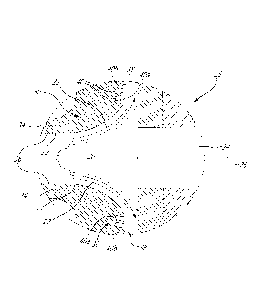
[0006] Reference is now made to the accompanying figures in which:
[0007] Fig. 1 is a schematic cross-sectional view of a gas turbine engine;
[0008] Fig. 2 is a partially-sectioned view of a centrifugal compressor of
such a
gas turbine engine, according to an embodiment of the present disclosure;
[0009] Fig. 2A is a cross-sectional view of portions of an impeller shroud
surface
of a centrifugal compressor such as the one shown in Fig. 2;
2
CA 02879923 2015-01-26
[0010] Fig. 3 is a perspective view of an impeller shroud for the centrifugal
compressor of Fig. 2;
[0011] Fig. 4 is a partial cross-sectional view of an impeller shroud of the
centrifugal compressor of Fig. 2, taken through the line IV-IV of Fig. 3,
showing a
circumferential groove configuration;
[0012] Fig. 5 is a partial cross-sectional view of an impeller shroud in
accordance
with an alternate embodiment of the present disclosure, showing an alternate
circumferential groove configuration;
[0013] Fig. 6 is an end view of an impeller shroud for a centrifugal
compressor in
accordance with another embodiment of the present disclosure, the impeller
shroud having at least partially circumferentially extending grooves and
groove
partitions;
[0014] Fig. 6A is a cross-sectional view of one of the groove partitions shown
in
Fig. 6, taken along the line VI-VI;
[0015] Figs. 7a-7b show graphs comparing the overall pressure ratio and the
overall efficiency of the compressor for a baseline impeller shroud versus a
treated impeller shroud;
[0016] Figs. 8a-8b show graphs comparing the impeller exit total temperature
and the impeller exit velocity for a baseline impeller shroud versus a treated
impeller shroud; and
[0017] Fig. 9 is a block diagram of a method of reducing flow blockage of a
compressible fluid, according to another embodiment.
DETAILED DESCRIPTION
[0018] Fig. 1 illustrates a turbofan gas turbine engine 10 of a type
preferably
provided for use in subsonic flight, generally comprising in serial flow
communication a fan 12 through which ambient air is propelled, a multistage
3
CA 02879923 2015-01-26
compressor 14 for pressurizing the air having an axial low pressure compressor
(LPC) 13 and a centrifugal high pressure compressor (HPC) 15, a combustor 16
in which the compressed air is mixed with fuel and ignited for generating an
annular stream of hot combustion gases, and a turbine section 18 for
extracting
energy from the combustion gases. The center axis 11 of the engine 10 is also
illustrated.
[0010] Of particular interest in the present disclosure is the centrifugal HPC
15,
although it is to be understood that the impeller shroud treatment as will be
described herein can be applicable to any centrifugal compressor of an aero
gas
turbine engine.
[0020] Fig. 2 shows a centrifugal compressor 15 (or simply "compressor" 15) of
the present disclosure in partial cross-section. The compressor 15 axially
receives a compressible fluid, increases the pressure of the compressible
fluid,
and conveys it in a substantially radial direction. The working or
compressible
fluid can be any fluid which can experience significant variations in density,
and
in most instances is air or another gas. The compressor 15 comprises at least:
an impeller 20, which increases the pressure of the compressible fluid before
conveying it downstream; and a surrounding impeller shroud 30, which houses
the impeller 20 and provides structure to the compressor 15. Both will now be
discussed in greater detail.
[0021] The impeller 20 of the compressor 15 can be any device which can rotate
about a central axis so as to increase the pressure of the compressible fluid.
The
impeller 20 has multiple impeller vanes 22, and is mounted to a shaft 24 which
rotates, along with the impeller 20, about a shaft axis 26.
[0022] The centrifugal compressor 15 also has an impeller shroud 30. The
impeller shroud 30 (or simply "shroud 30") houses or encloses the impeller 20,
thereby forming a substantially closed system whereby the compressible fluid
enters the shroud 30, is processed, and exits the shroud 30.
4
CA 02879923 2015-01-26
[0023] The shroud 30 has a shroud body 34, which makes up the corpus of the
shroud 30 and provides it with its structure and its ability to resist the
loads
generated by the compressor 15 when in operation. The shroud 30 also has a
shroud surface 32, which is the face of the shroud 30 that is exposed to the
compressible fluid, and which surrounds the impeller vanes 22. The shroud
surface 32 is radially spaced apart from the impeller vanes, thereby defining
a
gap therebetween. This gap extends along the length of the shroud surface 32.
The shroud surface 32 has a curved profile, which may match the profile of the
impeller vanes 22, and which extends between an inducer portion 36 and an
exducer portion 38 of the shroud surface 32. Both of these will now be
discussed
in greater detail.
[0024] Referring to Fig. 2A, the location and relative size of the inducer
portion 36
and the exducer portion 38 on the shroud surface 32 can vary for different
centrifugal compressors 15. For certain compressors 15, the location of the
inducer portion 36 and the exducer portion 38 is given in relation to a bend
portion 33, or "knee", of the shroud surface 32. The bend portion 33 can be
defined by a bend length, which begins at a point where the substantially
axial
compressible fluid starts to curve or bend, and ends at a point where the
compressible fluid first begins to flow in a substantially radial direction.
The bend
portion 33 is demarcated in Fig. 2A by lines L, which extend in a direction
normal
to the shroud surface 32 at the location where the flow transitions from an
axial
direction, and where it transitions to a substantially radial direction. The
inducer
portion 36 can be any part of the shroud surface 32 which is upstream of the
bend portion 33, and the exducer portion 38 can be any part of the shroud
surface 32 which is downstream of the bend portion 33.
[0025] For the compressor 15 shown in Fig. 2, the inducer portion 36
corresponds to the part of the shroud surface 32 in proximity to the inlet of
the
impeller 20. The inducer portion 36 in this embodiment is generally a straight-
line
segment which is parallel to the shaft axis 26, and corresponds to the portion
of
CA 02879923 2015-01-26
the shroud 30 that receives the compressible fluid. Inducer portions 36 having
other configurations are also within the scope of the present disclosure.
[0026] For the compressor 15 shown in Fig. 2, the exducer portion 38
corresponds to the part of the shroud surface 32 in proximity to the exit of
the
impeller 20. As shown in the embodiment of Fig. 2, the exducer portion 38 is a
substantially straight-line segment extending from the end of the curve of the
shroud surface 32. The exducer portion 38 extends radially with respect to the
shaft axis 26, and away therefrom. It will be appreciated that the exducer
portion
38 is not limited to this configuration. For example, and as shown in Fig. 2A,
the
exducer portion 38 can be a curved-line segment extending from the end of the
bend portion 33 of the shroud surface 32. The exducer portion 38 helps to
convey the compressible fluid downstream from the exit of the impeller 20,
such
as towards a diffuser system.
[0027] Returning to Fig. 2, the movement of the compressible fluid through the
compressor 15 can be described as follows. During operation of the compressor
15, the compressible fluid is conveyed through impeller 20 and is bounded by
the
shroud surface 32 of the shroud 30, along a fluid flow path C. The fluid flow
path
C begins in the shroud 30 at the inducer portion 36 and extends toward or
through the exducer portion 38. The fluid flow path C is located between the
exterior faces of the impeller vanes 22 and the shroud surface 32. As such,
the
fluid flow path C follows the contour of the shroud surface 32. The rotation
of the
impeller 20 causes the compressible fluid to be drawn axially into the inducer
portion 36, and further causes the compressible fluid to change direction
along
the fluid flow path C such that the compressible fluid is conveyed radially
through
the exducer portion 38.
[0028] The shroud 30 also has one or more circumferentially extending grooves
40 located within the exducer portion 38 of the shroud, examples of which are
shown in Figs. 2 to 3. The term "circumferential" refers to the direction
and/or
orientation of the grooves 40 in that they extend along either the entire
length, or
just a section, of the annular shroud surface 32. Each groove 40 extends into
the
6
CA 02879923 2015-01-26
shroud body 34 from the shroud surface 32, thereby forming a depression or
cavity extending into the shroud body 34. While a single circumferentially
extending groove 40 may be provided in the exducer portion 38 of the shroud
30,
when two or more such grooves 40 are provided, as depicted in Figs. 2-3, the
circumferentially extending grooves 40 may be substantially concentric
relative to
each other and thus form substantially concentric rings in the shroud surface
32.
These groove rings 40 need not be annularly uninterrupted, however, and
therefore may be comprises of a number of arcuate groove segments which
together make up each of the grooves 40. The grooves
40 are located within
the exducer portion 38. The term "within" when used to describe the location
of
the grooves 40 refers to the disposition of each groove 40, in that each
groove
40 is located at a point on the substantially straight or radial line segment
extending from the end of the bend portion 33 of the shroud surface 32. Many
other possible locations of the grooves 40 within the exducer portion 38 fall
within
the scope of the present disclosure.
[0029] The number of grooves 40 in the shroud 30 can vary. In most
embodiments, the number of grooves 40 will not exceed six. In some
embodiments, an example of which is provided in Fig. 2, the shroud 30 can have
a first circumferential groove 40a and a second circumferential groove 40b. In
addition to the number of grooves 40, their location relative to one another
can
also vary. For example, the second groove 40b can be disposed within the
exducer portion 38 downstream of the first groove 40a in the direction of the
fluid
flow path C. The spacing of the first and second grooves 40a,40b from each
other along the shroud surface can vary, and in some instances, can depend on
the width of the grooves 40 themselves.
[0030] Referring now to Figs. 4 and 5, each groove 40 has opposed wall
segments, shown as a first wall segment 42 extending from the shroud surface
32 into the shroud body 34, and a second wall segment 44 extending from the
shroud surface 32 into the shroud body 34. The first and second wall segments
42,44 of each groove 40 can be substantially flat or level lines defining the
extent
7
CA 02879923 2015-01-26
or width W of each groove 40. The relationship of the first wall segment 42
with
the second wall segment 44 is one that is "opposed and spaced apart", meaning
that the first and second wall segments 42,44 face one another across a gap,
and define the opposed sides of each groove 40.
[0031] The first and second wall segments 42,44 of each groove 40 are linked
together by a groove bottom segment 46. In most embodiments, the groove
bottom segment 46 forms the bottom or end of each groove 40, and defines its
width W. The groove bottom segment 46 can take many different profiles. For
example, in the embodiment shown in Fig. 4, the groove bottom segment 46 is
substantially flat. In another embodiment, an example of which is shown in
Fig. 5,
the groove bottom segment 46 is substantially curvilinear or rounded. The
compressible fluid first enters the grooves 40, reverses direction, and is
ejected
from the grooves 40. Such a curved groove bottom segment 46 may facilitate
this reversal of direction and ejection of the compressible fluid from groove
40. It
can thus be appreciated that many possible shapes and configurations of the
groove bottom segment 46 are possible.
[0032] In light of the preceding, it can be appreciated that the first wall,
second
wall, and groove bottom segments 42,44,46 define the contour and shape of
each groove 40. The first and second wall segments 42,44 extend into the
shroud body 34 to a groove depth D, and are spaced apart from one another by
a groove width W. Many possible groove depth D and groove width W values are
possible, and may depend upon numerous factors such as the desired surge
margin of the engine 10 and the efficiency of the compressor 15. For example,
the greater the groove depth D, the higher likelihood that the surge margin
will
increase, but at the expense of compressor efficiency. Similarly, a greater
groove
width W may improve communication between the flow of the compressible fluid
in the groove 40 and the fluid flow path C, but may also affect the
performance of
the compressor 15. It can thus be appreciated that selecting the values of
groove
depth D and groove width W can involve a trade-off between different engine
parameters.
8
CA 02879923 2015-01-26
[0033] Still referring to Figs. 4 and 5, both of the first and second wall
segments
42,44 are inclined at a nonzero groove angle e with respect to a normal N of
the
shroud surface 32. The term "both" encompasses the groove angle e of the first
wall segment 42 and the second wall segment 44, in that these two segments
42,44 are each inclined at the same nonzero groove angle e with respect to the
normal N. The expression "nonzero" refers to the value of the groove angle e.
This value can be any number other than zero, meaning that the first and
second
wall segments 42,44 are not substantially normal to the shroud surface 32.
[0034] The groove angle e can be measured in different ways, provided that it
is
measured relative to the normal N at that point on the shroud surface 32. This
is
more easily understood by comparing the groove angles e shown in Figs. 4 and
5. As can be seen, the groove angles e in both figures may have the same
absolute value, but their real values may differ. The normal N of the shroud
surface 32 at any given point along the shroud surface 32 is determined by
taking the tangent to the shroud surface 32 at that point, and drawing a line
perpendicularly to the tangent at that point.
[0035] Such an inclination of the first and second wall segments 42,44 may
advantageously help better direct the compressible fluid downstream and away
from the exducer of the impeller 20. This may result in less disruption to the
main
flow of the compressible fluid, may also lower the losses caused by flow
mixing,
and may increase overall efficiency. Furthermore, the use of inclined first
and
second wall segments 42,44 may reduce the number of grooves 40 which might
be needed for a given shroud 30, thereby further advantageously improving
machining and manufacturing costs.
[0036] The nonzero groove angle e at which the grooves 40 are inclined allows
for a more uniform reintroduction of the compressible fluid into the fluid
flow path
C as the compressible fluid is ejected from the groove 40. By providing such a
suitable groove angle e to the extent permitted by machining capacity, the
compressible fluid is able to re-enter the fluid flow path C along a direction
that is
substantially parallel to the fluid flow path C. In contrast, conventional
grooves
9
CA 02879923 2015-01-26
having wall segments inclined normal to the surface of the impeller shroud
reintroduce the compressible fluid perpendicularly to the flow path, and can
thus
interfere with the flow of the compressible fluid.
[0037] The absolute value of the groove angle e of the first and second wall
segments 42,44 can vary. In some embodiments, the groove angle e can be
chosen amongst a range of possible absolute values, such as an absolute value
between about 900 and about 450
.
[0039] The first and second wall segments 42,44 are inclined in a direction
against, or opposite, the fluid flow path C. Such an orientation of the first
and
second wall segments 42,44 allows the compressible fluid to eject from the
groove 40 in a direction aligned with the direction of the fluid flow path C.
[0039] In in the exemplary embodiments of Figs. 6 and 6A, each of the grooves
40 may be circumferentially discontinuous, and as such can have one or more
groove partitions 48. Each groove partition 48 can be a block or other similar
obstruction which is located within the groove 40 in question, thereby
occupying
the width W and some or all of the depth D of the groove 40.
[0040] Certain prior art shroud indentations trap a significant portion of the
gas
flow within the circumferential indentations, forcing them to circulate within
the
indentations. This prevents the gas from exiting the shroud, and can thus
adversely affect the overall operation of the compressor.
[0041] The optional groove partitions 48 can block the flow of the
compressible
fluid inside the same groove 40, thus preventing the compressible fluid from
flowing inside the groove 40 from one side of each groove partition 48 to its
other
side. In so doing, each groove partition 48 may advantageously force the
compressible fluid to exit the groove 40 faster than it might otherwise have
done
so, thus helping to overcome some of the problems described above. The groove
partitions 48 may also advantageously reduce the temperature rise which can
occur in the grooves 40 when the compressible fluid circulates in the grooves
40.
CA 02879923 2015-01-26
[0042] Each groove partition 48 can take different shapes and configurations.
In
one possible embodiment, one or more groove partitions 48 can consist of a
block extending across the width W of the groove 40, and extending from the
groove bottom segment 46 so as to arrive substantially flush with the shroud
surface 32. In such a configuration, the groove partition 48 advantageously
does
not significantly interfere with the fluid properties of the shroud surface
32. In
another possible embodiment, one or more groove partitions 48 can consist of a
block extending across the width W of the groove 40. Such a groove partition
48
can vary in height, such that it begins within the groove 30 at a height lower
than
the shroud surface 32, and rises from the inner part of the groove 40 (i.e.
the part
closest to the impeller 20) to arrive flush with the shroud surface 32 at the
outer
part of the groove 40 (i.e. the part furthest from the impeller 20).
[0043] In yet another possible embodiment, an example of which is provided in
Fig. 6A, each groove partition 48 can have one or two flow exit ramps 43
disposed on opposed circumferential ends of the groove partition 48. Each flow
exit ramp 43 can help to guide the circulating compressible fluid out of the
groove
40 in which the groove partition 48 is located, thus helping to prevent the
recirculation of the compressible fluid within the groove 40. The
configuration of
the flow exit ramps 43 can vary. For example, the flow exit ramp 43 can be
defined by an inclined flat plane which extends across the width W of the
groove,
and which rises at an incline from the groove bottom segment 46 until the
shroud
surface 32. Alternatively, the flow exit ramp 43 can be defined by an inclined
curved plane, similar to a "ski jump", which extends across the width W of the
groove, and which rises along a curved profile from the groove bottom segment
46 until the shroud surface 32.
[0044] The choice between the possible shapes and configurations of the groove
partitions 48 can be determined based upon consideration of the following non-
exhaustive list of factors: their effect on the performance of the compressor
15,
their difficulty to machine or install in the grooves 40, and the intended use
of the
compressor 15.
11
CA 02879923 2015-01-26
[0045] The groove partitions 48 divide the grooves 40 in which they are
located
into groove slots 49. The number and angular width of each of the groove slots
49 can vary depending on the number and location of the groove partitions 48
for
a particular groove. In some embodiments, the groove partitions 48 of a given
groove 40 are disposed at regular or irregular angular intervals from an
adjacent
groove partition 48. The angular interval can vary or remain constant for a
single
groove 40, and between adjacent grooves 40.
[0046] Figs. 7a-7b and 8a-8b show graphs of certain parameters of a compressor
for a shroud 30 without circumferential grooves 40 (referred to in Figs. 7 and
8 as
the "Baseline") versus a shroud 30 with the circumferential grooves 40
(referred
to in Figs. 7 and 8 as "casing treatment" or "CT"). The values and trends
shown
in the graphs are provided for the sole purposes of comparing and contrasting
the two types of shrouds 30. The curves of these graphs may vary depending on
numerous factors, and thus, so may the extent by which reliable comparisons
can be drawn. It will be appreciated that the performance of the compressor 15
is
not limited to, or defined by, the curves shown.
[0047] The graph of Fig. 7a plots the overall pressure ratio as a function of
the
mass flow rate of the compressible fluid for a compressor having a "baseline"
shroud , versus the compressor 15 having the "treated" shroud 30. As can be
seen, the curves for both types of shrouds are substantially similar, with the
"treated" shroud 30 showing improved surge margin over the "baseline" shroud.
[0048] The graph of Fig. 7b plots the overall efficiency of the compressor 15
as a
function of the mass flow rate of the compressible fluid for a compressor
having
a "baseline" shroud, versus the compressor 15 having the "treated" shroud 30.
As can be seen, the overall efficiency of the compressor 15 having the
"treated"
shroud 30 can be greater for most mass flow rates when compared to the
compressor having the "baseline" shroud, which is an indication of improved
compressor 15 performance.
12
CA 02879923 2015-01-26
[0049] Advantageously, and in contrast with certain prior art treated
compressor
shrouds, there does not appear to be a trade-off between compressor 15
performance (as represented by pressure ratio and surge margin) and overall
compressor efficiency for compressors 15 having the shroud 30 with
circumferential grooves 40 described above.
[0050] The graph of Fig. 8a plots the total temperature of the compressible
fluid
at the exit of an impeller as a function of the span of the impeller. Two
curves are
produced. The "Imp_Baseline" curve represents the data for a compressor
having a "baseline" shroud, and the other "Imp_CT" curve represents the data
for
the compressor 15 having the "treated" shroud 30. As can be seen, the
"treated"
shroud 30 may advantageously generate lower total temperatures near the tip of
the impeller, and substantially the same total temperatures as the "baseline"
shroud for other locations along the impeller.
[0051] The graph of Fig. 8b plots the velocity of the compressible fluid at
the exit
of an impeller as a function of the span of the impeller. Two curves are
produced.
The "Imp_Baseline" curve represents the data for a compressor having a
"baseline" shroud, and the other "Imp_CT" curve represents the data for the
compressor 15 having the "treated" shroud 30. As can be seen, the "treated"
shroud 30 may advantageously have a fuller velocity profile when compared to
that of the "baseline" shroud along all locations of the impeller.
[0052] A method of reducing flow blockage of a compressible fluid at an exit
of
an impeller of a centrifugal compressor is also provided. Referring to Fig. 9,
the
centrifugal compressor of the method 100 disclosed herein is similar to the
compressor 15 described above.
[0053] Flow blockage is a phenomenon observed in many compressors. It is
known that the flow of the compressible fluid at the exit of the impeller is
highly
complex. The pressure of the compressible fluid is raised rapidly after the
impeller inlet, starting at the impeller bend area. The combination of the
rapid
rise in pressure and the relatively high curvature of the shroud surface can
cause
13
CA 02879923 2015-01-26
a relatively high adverse pressure gradient to develop as the compressible
fluid
negotiates the curved shroud surface. This results in a build-up of the
boundary
layer due to the deceleration of the compressible fluid, and leads to increase
flow
blockage. This flow blockage can reduce the pressure gains achieved by the
compressor and cause flow separation.
[0054] The method 100 involves conveying the compressible fluid substantially
parallel to the shaft axis along the fluid flow path and through the inducer
portion,
identified in Fig. 9 with the reference number 102. This can occur, for
example,
when the impeller is rotating, thereby drawing the compressible fluid through
the
inducer portion.
[0055] The method 100 also involves conveying the compressible fluid radially
away from the shaft axis along the fluid flow path and through the exducer
portion, identified in Fig. 9 with the reference number 104. This can occur,
for
example, when the pressurized compressible fluid leaves the exit of the
impeller.
[0056] The method 100 also involves recirculating the compressible fluid
between the fluid flow path and the one or more circumferential grooves
described above, identified in Fig. 9 with the reference number 106. The
recirculation of the compressible fluid 106 can involve the compressible fluid
being injected or inserted into the grooves. It can also involve removing the
compressible fluid from within the grooves. The recirculation of the
compressible
fluid in 106 may help to alleviate the flow blockage associated with
conventional
exits of impellers by breaking up relatively large flow vortices into smaller
flow
vortices. These smaller flow vortices may have less permanence and be easier
to dissipate. They may also be confined closer to the grooves, which may
improve flow conditions to components downstream of the compressor, such as
a diffuser system.
[0057] The above description is meant to be exemplary only, and one skilled in
the art will recognize that changes may be made to the embodiments described
14
CA 02879923 2015-01-26
without departing from the scope of the invention disclosed. Such
modifications
are intended to fall within the appended claims.