Note : Les descriptions sont présentées dans la langue officielle dans laquelle elles ont été soumises.
CA 02880071 2015-04-17
,
- 1 -
Modular tower of a wind power plant
The invention relates to a tower of a wind power plant, having a lower part in
the
form of a lattice tower or truss tower with at least two corner bars, and an
upper part
in the form of a cross-sectionally substantially round tubular tower, wherein
each
particular corner bar is put together from a plurality of steel tube profiles
that are
connected together in the longitudinal direction.
Developments in wind energy plants to be erected inland are leading to ever
higher
hub heights of above 100 m in order to utilize greater and more constant wind
speeds
and thus to improve the efficiency of these wind energy plants. However,
higher
tubular towers having larger and more powerful rotors and generators require
at the
same time an increase in the wall thicknesses and diameters of the tower
segments in
order to meet the greater structural-mechanical demands that result therefrom,
such
as rigidity, protection against buckling and fatigue strength. However, the
increase in
the diameters of the tower segments also results in it no longer being
possible to
transport the prefabricated tubular tower segments with the conventional
transversely oriented construction type on many roads on account of
restrictions, for
example bridge clearance heights of 4.4 m.
A possible solution, which is proposed for example in DE 603 17 372 T2 and
also in
WO 2009/048955 A1, is what is referred to as the longitudinally oriented
construction type, in particular in the lower tower region, in the case of
which the
diameters of the finished tubular tower segments are ultimately more than 4.4
m. In
this case, tubular tower sections are first put together from a plurality of
arcuate shell
segments at the construction site, i.e. at the location of the wind turbine,
and the
tubular (annular) tower segments produced in this way are connected to form
the
overall tower. In order to avoid welding at great heights, the shell segments
in the
tower construction known from DE 603 17 372 T2 are provided with perforated
CA 02880071 2015-04-17
- 2 -
horizontal and vertical flanges which allow the shell segments to be connected
by
screws. However, this solution has a number of disadvantages. For example, in
the
case of large shell segments, deformations are to be expected on account of
the dead
weight of the shell segments, it being possible for said deformations to
result in
handling or fitting problems during assembly. On the other hand, in the event
of
subdivision into a large number of small shell segments, the number of screwed
connections to be produced is relatively high, thereby increasing the assembly
and
also maintenance costs for re-tightening the screws.
In addition to wind power plants having a tubular tower and wind power plants
having a lattice tower (truss tower), wind power plants having towers with a
hybrid
construction type, which have a lower lattice tower (truss tower) and an upper
tubular tower connected thereto, are also known. DE 10 2006 056 274 A1
discloses a
tower of the type mentioned at the beginning, which has a lattice tower with
at least
three corner bars in its lower part and a cross-sectionally round tubular
tower in its
upper part, wherein the upper connection region of the lower part is connected
to the
lower connection region of the upper part by means of a transition body in the
transition region. The transition body is in this case formed in a manner of a
truncated
conical casing, wherein the corner bars extend into the transition region and
are at
least sectionally welded to the truncated conical casing in the transition
region
between the upper connection region of the lower part and the lower connection
region of the upper part. The lattice tower has intersecting struts which
connect the
corner bars of the lattice tower together. The corner bars of the lattice
tower are
formed from standardized hollow profiles, preferably from steel tubes.
An embodiment of the present invention provides a tower of the type mentioned
at
the beginning, which, while having good transportability of its components,
affords
cost-effective production and easier assembly of its components.
In order to achieve this object, embodiments of the invention provide a tower
of a
wind power plant or wind energy plant, having a lower part in the form of a
lattice
tower or truss tower with at least two corner bars, and an upper part in the
form of a
CA 02880071 2015-04-17
- 3 -
cross-sectionally substantially round tubular tower, wherein each particular
corner
bar is put together from a plurality of steel tube profiles that are connected
together in
the longitudinal direction, wherein each particular corner bar is put together
from at
least three steel tube profiles which are provided with perforated flanges for
holding
screws, wherein the corner bars are connected together by cross struts and/or
tension struts attached to the flanges, and wherein the steel tube profiles of
each
particular corner bar are spirally welded steel tube profiles.
The upper part of the tower, which is embodied in the form of a cross-
sectionally
substantially round tubular tower, preferably begins from a height of 60 m.
This upper
part of the tower can be realized in a conventional, transversely oriented
construction
type, since the diameter that meets the structural-mechanical demands should
to this
extent normally be beneath the limit of 4.4 m that is critical from a
logistical point of
view. The lower part of the tower, which is in the form of a lattice tower or
truss tower
with at least two, preferably three corner bars, wherein each particular
corner bar is
put together from at least three steel tube profiles that are connected
together in the
longitudinal direction and are provided with perforated flanges for holding
mechanically detachable connecting means, simplifies the transport and
assembly of
the tower. Since the forces to be absorbed are distributed to a number of
corner bars,
the latter can be dimensioned in a considerably narrower manner than the
corresponding lower part of a conventional, cross-sectionally substantially
round
tubular tower. The corner bars can be handled in a much easier manner from a
logistical point of view. The number of individual steel tube profiles
provided with
flanges can in this case be varied and is dependent on the hub height and the
weight of
the wind power plant, which consists substantially of a generator, gearing and
rotor
blades. For example, the lattice tower of the hybrid tower can have four, five
or six
corner bars. The subdivision of each particular corner bar into at least three
steel tube
profiles which are connected together in the longitudinal direction by
mechanically
detachable connecting means at the flanges considerably simplifies the
transport and
assembly of the components of a hybrid tower for a wind power plant. The
profile
diameter of the steel tubes used for each particular corner bars is in this
case
preferably substantially identical along the overall length of the corner bar.
The steel
CA 02880071 2015-04-17
,
,
- 4 -
tube profile is merely cut in a different manner depending on the attachment
angle to
the flanges. This identical-part strategy (identical-part construction)
results in
reduced unit costs. Mechanically detachable connecting means should be
understood
in the present context as meaning, among other things, screws, bolts and
lockbolts.
The steel tube profiles that are used for the corner bars of the tower are
produced by
spiral welding. In difference to the production of longitudinally welded steel
tube
profiles, in which each tube diameter requires a particular sheet width,
spiral tube
production is distinguished by the fact that steel tubes having different tube
diameters
can be produced from one strip width or sheet width. The use of steel tube
profiles
produced by spiral welding is advantageous from an economic point of view. The
steel
sheets used in this case are preferably hot-rolled, micro-alloyed steel sheets
which
have an upper yield strength (ReH) of at least 355 N/mm2 or 420 N/mm2. The
steel
tube profiles (corner bars) of the tower are particularly preferably produced
from
high-strength steel sheets having an upper yield strength (ReH) of for example
at least
500 N/mm2 or 700 N/mm2. As a result, the weight of the steel tube profiles
(corner
bars) can be reduced, with the result that the transport and assembly are
further
simplified.
The wall thicknesses and diameters of the steel tube profiles are dependent in
particular on the tower height and the number of corner bars. The steel tube
profiles
that are used for the corner bars of the tower have for example a wall
thickness in the
range from 15 mm to 30 mm and an outside tube diameter in the range from 500
mm
to 1800 mm, preferably in the range between SOO mm and 1200 mm.
In order to reliably absorb transverse forces that arise in the lower part of
the tower,
the individual corner bars are connected together by cross struts and/or
tension
struts attached to the flanges. The flanges of the steel tube profiles thus
have a
multiple attachment function; they serve to longitudinally attach the steel
tube
profiles forming each particular corner bar and additionally serve to
transversely
attach and/or diagonally attach the corner bars together, wherein each of
these
CA 02880071 2015-04-17
- 5 -
attachment means is executed preferably by means of screw connection. On
account
of this multiple attachment function, the flanges of the wind energy plant
tower can
also be referred to as multi-attachment flanges.
The cross struts are preferably formed from substantially horizontally
extending steel
profiles. These can be, for example, bend pieces or rolled profiles, in
particular angled
struts or struts in the form of a U-profile. In addition, these cross struts
are preferably
formed in an identical manner in as much as they all have the same cross-
sectional
profile and the same cross-sectional dimensions. However, the cross struts are
cut to
different lengths, namely dimensioned in a shorter manner, with increasing
tower
height.
By way of tension struts attached to the flanges, the stability of the overall
tower
according to the invention can likewise be ensured or further increased. The
transverse struts can in this case be embodied as steel cables, preferably
pretensioned
steel cables, or as bend pieces or rolled profiles. When steel cables are used
as tension
struts, these can be easily transported to the installation site of the tower
in the reeled
state. Furthermore, tolerance problems can be ruled out with regard to the
steel
cables, since the steel cables can be cut to length as required at the
location of the
tower. In an advantageous configuration of the tower according to embodiments
of
the invention, one or more of the diagonal struts, for example steel cables,
are each
provided with a tensioning device for length adaptation.
In a further preferred configuration of embodiments of the invention, the
connecting
points or ends of the steel tube profiles are provided with flaps which have
through-
holes or through-bores for attaching cross struts and/or diagonal struts.
The flaps can be separately manufactured parts which are each welded to a
flange at
the end of the steel tube profile. Alternatively, however, the flap can also
be formed in
one piece with the flange. In the second case, the flap is produced, for
example, by
being formed from the steel-sheet blank that defines the flange. In both
cases, the flap
CA 02880071 2015-04-17
,
,
- 6 -
and the flange can be welded to the steel tube profile, wherein the flap is
then oriented
substantially perpendicularly to the flange.
In the case of the preferred use of bend pieces or rolled profiles as tension
struts, it is
possible to connect the tension struts together at their crossing point in
order to
further increase the stability of the overall tower. The tension struts are in
this case
connected at the crossing point for example by screws or other detachable
mechanical
connecting means. This connection can advantageously already be carried out
during
the prefabrication of the tower components.
Further preferred and advantageous configurations of the wind power plant
tower
according to embodiments of the invention are described herein.
The invention is explained in more detail in the following text by way of a
drawing
that illustrates a number of exemplary embodiments and in which,
schematically:
Fig. 1 shows a perspective illustration of a wind power plant
tower according
to the invention;
Fig. 2 shows an enlarged illustration of the lower part of the
tower from Fig. 1;
Fig. 3 shows a perspective illustration of a lower section of
the lattice tower or
truss tower of a wind power plant tower according to a further
exemplary embodiment;
Fig. 4 shows an enlarged illustration of the detail A of the lattice tower
or truss
tower from Fig. 3;
Fig. 5 shows an enlarged illustration of the detail B of the
lattice tower or truss
tower from Fig. 3; and
CA 02880071 2015-04-17
- 7 -
Fig. 6 shows a front view of a section of the lattice tower or truss
tower from
Fig. 3 in the region of the connection of the steel tube profiles of two
corner bars.
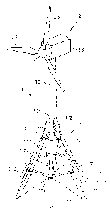
The tower 1, illustrated in the drawing, of a wind power plant 2 is
constructed from a
lower part 1.1 in the form of a lattice tower or truss tower and an upper part
1.2 in the
form of a cross-sectionally round tubular tower.
Mounted on the upper end of the tubular tower 1.2 is a wind power plant (wind
energy plant) 2 which is mounted so as to be rotatable about a substantially
vertically
extending axis. The wind power plant 2 comprises a rotor 2.1 having rotor
blades 2.2
which are preferably rotatable about their respective longitudinal axis and
are thus
adjustable in an infinitely variable manner, and a generator arranged in the
nacelle
housing 2.3, the shaft of said generator being connected to the rotor 2.1 for
conjoint
rotation via a transmission and a clutch.
In the exemplary embodiment shown here, the lattice tower or truss tower 1.1
has six
corner bars 1.10. However, it can also have more or fewer than six corner
bars. In any
case, it has at least three corner bars 1.10, their horizontal distance
increases from the
upper tubular tower 1.2 in the direction of the ground or foundation. The
preferably
substantially rectilinear corner bars 1.10 thus form a three- or more-legged
tower
structure, the legs of which are spread at an acute angle with respect to one
another.
Each of the corner bars 1.10 is put together from at least three steel tube
profiles 1.11,
1.12 which are connected together in the longitudinal direction and to this
end are
provided at their connecting points with perforated flanges 1.13 for holding
for
example screws (not shown). The flanges 1.13 are configured for example as
annular
flanges. Each particular flange or annular flange 1.13 has a plurality of
through-holes
1.14 which are arranged in a regularly spaced apart manner on a common
reference
circle (cf. Fig. 2).
CA 02880071 2015-04-17
- 8 -
Preferably, the steel tube profiles 1.11, 1.12 that are used for the corner
bars 1.10 are
identical parts which are spirally welded. The arcuate steel sheets or steel
sheets
formed in a round shape which are used for the production thereof are for
example
hot-rolled steel sheets having a yield strength of at least 350 N/mm2.
However,
higher-strength steel sheets can also be used to produce the steel tube
profiles of the
corner bars 1.10, for example steel sheets having a yield strength in the
range from
500 to 700 N/mm2.
The steel tube profiles 1.11, 1.12 of each particular corner bar 1.10
preferably have a
wall thickness in the range from 15 mm to 30 mm. Their diameter is for example
in
the range from 500 mm to 1800 mm. Preferably, the steel tube profiles 1.11,
1.12 that
are used for the corner bars 1.10 are produced from standard tubes.
Each particular annular flange 1.13 is preferably attached cohesively to one
of the
ends of the steel tube profile 1.11, 1.12 used to construct a corner bar 1.10,
for
example by means of fillet welding. However, a force-fitting and/or form-
fitting
connection between the annular flange 1.13 and the associated steel tube end
for
example by way of a screw connection, in the case of which the steel tube end
is
provided with an external thread and the annular flange with a corresponding
internal thread, is also possible.
Each particular annular flange 1.13 is arranged in a horizontal plane. To this
end, the
ends, provided with the annular flanges 1.13, of the steel tube profiles 1.11,
1.12 are
cut obliquely such that each particular cut end of the steel tube profile
1.11, 1.12 ends
in a substantially horizontal manner in the fully assembled state of the
lattice tower or
truss tower 1.1.
The corner bars 1.10 are connected together by cross struts 1.15. To this end,
use is
made of the same annular flanges 1.13 which connect the steel tubes 1.11,
1.12,
preferably standard tubes, together.
CA 02880071 2015-04-17
- 9 -
The cross struts 1.15 are formed from steel profiles and extend substantially
horizontally. Those cross struts 1.15 which are arranged at the same height
are
embodied as identical parts. The length of the cross struts 1.15 depends in
this case on
their attachment height. With increasing tower height, the length of the cross
struts
1.15 attached to the annular flanges 1.13 decreases.
The tower 1 according to embodiments of the invention, at least the lower
lattice
tower part 1.1 thereof, thus has a modular structure, using standardized steel
profiles
1.11, 1.12, 1.15.
The cross struts 1.15 are embodied for example as U-profiles (cf. Fig. 2).
However,
they can also have some other profile shape, for example an L-profile or T-
profile.
The ends of each particular cross strut 1.15 preferably have end sides 1.16
that are
formed in a concave or dovetail manner or are polygonally indented. As a
result, the
bearing surface or contact surface between the cross strut 1.15 and annular
flange
1.13 can be enlarged (cf. Fig. 2).
In order to ensure or further increase the required stability of the overall
tower 1,
provision can be made of additional tension struts 1.17 which are fastened in
each
case in the flange region such that they extend diagonally in the truss which
is defined
by two adjacent corner bars 1.10 and two cross struts 1.15 extending
substantially
parallel to one another.
The tension struts 1.17 are formed for example from wire cables. The ends of
the wire
cables 1.17 are fastened to the through-openings 1.14 in the annular flanges
1.13 via
suitable fastening means. For the length adaptation thereof, the tension
struts or wire
cables 1.17 can each be provided with a tensioning device (not shown). The
tension
struts or wire cables 1.17 and the bolts are not illustrated in Fig. 2 for the
sake of
clarity.
CA 02880071 2015-04-17
- 10 -
The upper tower part 1.2, which is configured as a cross-sectionally round
tubular
tower, starts from a height of for example about 60 m. It can be embodied in a
conventional, transversely oriented construction type and accordingly be put
together
from a plurality of annular tube segments.
The tubular tower 1.2 of the tower 1 is preferably embodied as a conical steel
tube
tower. Alternatively, however, it can also be embodied as a cylindrical steel
tube
tower.
At its end facing the truss tower or lattice tower 1.1, the tubular tower 1.2
has a
conical or truncated conical-casing-shaped longitudinal section. The upper
ends of the
corner bars 1.10 are attached to this lower section 1.21 of the tubular tower
1.2. The
upper steel tubes 1.12 of the corner bars 1.10 can in this case extend into
the
truncated conical-casing-shaped or conical longitudinal section 1.21 of the
tubular
tower 1.2 and are then connected to the inner side of the tubular tower 1.2,
for
example welded thereto. However, at its lower end, the tubular tower 1.2 can
also
have a circular-disc-shaped or annular-disc-shaped connecting plate (not
shown)
having a plurality of fastening holes at which the upper steel tubes 1.12 of
the corner
bars 1.10 are attached or screwed via annular flanges fastened thereto.
The height of the overall tower 1 put together from the lattice tower 1.1 and
the
tubular tower 1.2, or the hub height of the rotor 2.1 is for example about 110
m.
Fig. 3 illustrates a further exemplary embodiment of the lower part 1.1,
configured as
a lattice tower or truss tower, of a wind power plant tower. The upper part of
the
tower, which, in a similar manner to in Fig. 1, is formed from a cross-
sectionally
substantially round tubular tower, is not shown in Fig. 3.
In this exemplary embodiment, the lattice tower or truss tower 1.1 has at
least two
corner bars 1.10 which are each put together from at least three steel tube
profiles
1.11, 1.12 that are connected together in the longitudinal direction. To this
end, the
steel tube profiles 1.11, 1.12 are provided at their connecting points with
perforated
CA 02880071 2015-04-17
- 11 -
flanges 1.13 for holding detachable mechanical connecting means, for example
screws.
Each of the flanges 1.13 according to Fig. 4 has a plurality of through-holes
1.14 for
holding the connecting means.
Furthermore, flaps 1.18 are provided at the connecting points or ends of the
steel tube
profiles 1.11, 1.12. The flap 1.18 and the flange 1.13 are welded to the steel
tube
profile 1.11 and 1.12, wherein the flap 1.18 is oriented substantially
perpendicularly
to the flange 1.13.
If the flap 1.18 is manufactured as a separate part, it is preferably also
welded to the
flange 1.13 (cf. Fig. 4). However, it is also within the scope of the
invention to form the
flap 1.18 and the flange 1.13 together in one piece. In this case, the flap
1.18 would be
produced for example by being formed from the steel-sheet blank that defines
the
flange 1.13.
Each particular flap 1.18 likewise has a plurality of through-holes 1.19 for
holding
detachable mechanical connecting means. The flaps 1.18 serve for attaching
tension
struts 1.17. Furthermore, cross struts 1.15 can also be attached to the flaps
1.18.
Alternatively or in addition, the cross struts 1.15 can also be attached to
the flanges
1.13, however.
The exemplary embodiment according to Figures 3 and 4 affords the possibility
of
cutting the ends of the steel tube profiles 1.11, 1.12 to length substantially
perpendicularly (at right angles) to the longitudinal axis, i.e. chamfering of
the tube
ends - as illustrated in Fig. 2 - is not provided here. The attachment of the
cross struts
1.15 to the steel tube profiles 1.11, 1.12 is then possible, in spite of their
substantially
right-angled cut ends or the substantially perpendicular orientation of the
flanges 1.13
with respect to the steel tube profile longitudinal axis, without bending the
ends of the
cross struts 1.15, since the latter are in this case attached to the flaps
1.18. The flaps
1.18 thus make it possible to compensate the attachment angle between the
cross
strut 1.15 and the steel tube profile longitudinal axis at any desired
inclination angles
of the steel tube profile longitudinal axis (corner bar longitudinal axis).
CA 02880071 2015-04-17
- 12 -
The tension struts 1.17, which are embodied as bend pieces or rolled profiles
in the
exemplary embodiment according to Figures 3 to 6, are preferably connected
together
in their intersecting region 1.20. In order to connect or fix the tension
struts 1.17 in
the intersecting region 1.20, mechanical detachable connecting means, for
example
screws are again used. The connection or pre-fixing of the tension struts 1.17
in the
intersecting region 1.20 can already take place during prefabrication of the
tension
struts 1.17, with the result that the assembly of the lattice tower or truss
tower 1.1 at
the installation site of the tower is simplified or shortened.
The embodiment of the tower according to the invention is not limited to the
exemplary embodiments illustrated in the drawing. Rather, numerous variants
are
conceivable which, even in the case of a configuration that deviates from the
exemplary embodiment shown, make use of the invention specified in the
accompanying claims. Thus, for example instead of steel cables 1.17, it is
also possible
for steel profile bars, for example L-profile-shaped bend pieces, to be
attached as
tension struts to the flanges 1.13 of the corner bar tubes 1.11, 1.12.