Note : Les descriptions sont présentées dans la langue officielle dans laquelle elles ont été soumises.
CA 02881236 2015-02-06
WO 2014/022917
PCT/CA2013/000698
REFLECTIVE MATERIAL SENSOR
TECHNICAL FIELD
The present relates to material sensors, and more particularly to a sensor for
sensing reflective materials.
BACKGROUND
Precipitation sensors have been developed to determine the presence of
water in its vapor, liquid and solid forms, but usually the sensor is immersed
in
the material. Non-immersed sensing is a significant challenge. One example
of a non-immersed sensor is the Bosch vehicle windshield rain sensor
(Optical Sensor US Patent 6,376,824 by Michenfelder et al) used to operate
windshield wipers. This sensor depends on the change in refraction of a
reflected light beam against glass when water is on the outer glass surface.
However, it has poor sensitivity for snow, unless the glass can be heated
enough to melt the snow next to the glass. This would be difficult to
facilitate
without making the vehicle occupants too uncomfortable and initially, in cold
environments, would not work at all until the heating reached an acceptable
level for the sensor to be engaged.
BRIEF SUMMARY
We have invented a sensor that uses a reflective rather than refractive
technique, and as such is very welt suited to determining the presence of
winter precipitation such as snow, sleet, frost, ice or ice pellets. A
radiation
source such as a LED is oriented to radiate through a transparent material
such as glass, at an angle that does not cause a surface reflection back to
the
radiation sensor. When a reflective material such as winter precipitation is
on
the transparent material surface, a radiation sensor such as but not limited
to
a photo transistor, photo diode or light dependent resister adjacent to the
radiation source senses the radiation reflection.
CA 02881236 2015-02-06
WO 2014/022917
PCT/CA2013/000698
Accordingly, there is provided a sensor for sensing reflective material, the
sensor comprising:
a housing having a transparent window;
a sensor mount located in the housing and angled away from a
housing wall;
a radiation emitter mounted in the sensor mount for emitting radiation
along a first axis through the transparent window, the transparent window
having an amount of the reflective material located thereon; and
a radiation detector mounted in the sensor mount and located adjacent
the radiation emitter, the radiation detector being located to receive
reflected
radiation from the reflective material along a second axis, the first axis
being
angled towards the second axis.
In one example, the sensor includes two radiation emitters each located on
either side of the radiation detector, the two radiation emitters being
mounted
to emit radiation along their respective first axes through the transparent
window towards a common focal point on an outer surface of the transparent
window. The sensor mount includes two spaced apart cavities aligned along
the respective first axes in which the radiation emitters are located, and
another cavity aligned along the second axis in which the radiation detector
is
located.
In one example, the sensor mount is located at a junction between the
housing wall and a housing floor so that sensor mount is angled away from
the housing wall.
In another example, a baffle extends into the housing from the housing wall.
In another example, a temperature sensor is located on a lower surface of the
transparent window.
2
CA 02881236 2015-02-06
WO 2014/022917
PCT/CA2013/000698
In yet another example, a baffle wall extends into the housing from the
housing wall; and a temperature sensor is located on a lower surface of the
transparent window.
In one example, the radiation emitter is a Light Emitting Diode (LED).
In one example, the radiation sensor is a photo transistor or photo diode
located adjacent to the radiation emitter so as to detect reflected radiation.
In another example, the radiation emitter is disposed so that radiation is
emitted through the transparent window at an angle that does not cause a
surface reflection back to the radiation detector. A controller is located in
the
housing and is connected to a variable resistor, the radiation detector, the
radiation emitter and the temperature sensor. A controller is located in the
housing and is connected to a fixed resistor, the radiation detector, the
radiation emitter and the temperature sensor.
In one example, the radiation detector is an integrated circuit having a photo
transistor, a photo diode or a light dependent resister located adjacent to
the
radiation emitter so as to detect reflected radiation.
In another example, the reflective material is winter precipitation. The
winter
precipitation is snow, sleet, frost, ice or ice pellets.
In one example, the reflective material is non-winter precipitation. The non-
winter precipitation is reflective liquids, dirt, or particulate material
suspended
in liquids.
In one example, the sensor is mounted for use on motorized transportation
including trucks, cars, motor bikes, recreational vehicles, trains, or boats.
3
CA 02881236 2015-02-06
WO 2014/022917
PCT/CA2013/000698
In another example, the sensor is mounted for use on solar panels and trough
reflectors.
In yet another example, the sensor is mounted for use on sidewalks,
driveways, walkways, roads, roofs, or infrastructure projects.
In another example, the sensor is mounted for use with greenhouses, atriums,
windows, freezer glass doors, skylights; on planes, helicopters; food
services,
freezers /fridges, spacecraft, buildings; for landscaping such as grass and
garden maintenance, crops; or for weather determination, climate, ecosystem
preservation; or for medical applications and storage of tissues and cells,
sterilizations; or for food preparation and preservation, and the like.
In another example, the sensor is used in solar applications for building
materials including decking, walls or shingles.
BRIEF DESCRIPTION OF THE DRAWINGS
In order that the discovery may be readily understood, embodiments are
illustrated by way of example in the accompanying drawings.
Figure 1A illustrates top view of a sensor;
Figure 1B illustrates a side view of the sensor showing radiation emitted and
radiation reflected;
Figure 2 illustrates an exploded view of the sensor;
Figure 3 illustrates the sensor's field of view.
Figure 4 is diagrammatic representation of communication between sensor
components in one example of the sensor; and
4
CA 02881236 2015-02-06
WO 2014/022917
PCT/CA2013/000698
Figure 5 is diagrammatic representation of communication between sensor
components in an alternative example of the sensor.
Further details of the device and its advantages will be apparent from the
detailed description included below.
DETAILED DESCRIPTION
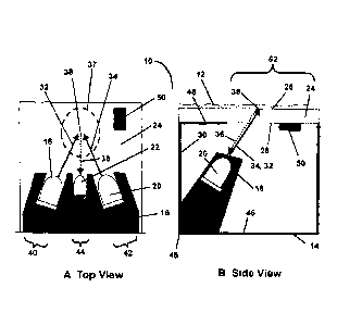
Referring to Figures 1A, 1B and 2, there is illustrated generally at 10 a
sensor
for sensing reflective material 12. In one example, the reflective material is
winter precipitation such as, for example, snow, frost, ice or ice pellets. In
another example, the reflective material is non-winter precipitation such as
reflective liquids, dirt, or particulate material suspended in liquids.
Broadly
speaking, the sensor 10 includes a housing 14, a sensor mount 16, two
radiation emitters (radiation sources) 18, 20, and a radiation detector
(radiation sensor) 22. The housing 14 has a transparent window 24 which
includes an upper surface 26 and a lower surface 28 which is disposed
towards the inside of the housing 14. The transparent window 24 has an
amount of accumulated reflective material 12 located thereon. The sensor
mount 16 is located in the housing 14 and angled away from a housing wall
30. The radiation emitters 18, 20 are mounted in the sensor mount 16. The
radiation emitter 18, 20 each have a first axis 32, 34. Radiation is emitted
from the radiation emitters 18, 20 along their respective axes 32, 34 towards
and through the transparent window 24 until it contacts the reflective
material
12. The radiation detector 22 is mounted in the sensor mount 16 and
adjacent and between the radiation emitters 18, 20. The radiation detector 22
is located to receive the radiation that is reflected back from the reflective
material 12 located on the transparent window 24 along a second axis 36.
The first axes 32, 34 of the radiation emitters 18, 20 are both angled towards
the second axis 36. The two radiation emitters 18, 20 emit radiation towards
a common focal point 38 on the upper surface 26 of the transparent window
24 and at a deviation from normal such that their radiation is not mirror
reflected to the radiation detector 22 from the upper or lower transparent
5
CA 02881236 2015-02-06
WO 2014/022917
PCT/CA2013/000698
window surfaces. The deviation from normal is also not large enough to cause
all radiation to be to be reflected back into the housing 14. The radiation
detector 22 is directed to the radiation emitter common focal point 38 on the
upper surface of the transparent window.
Referring briefly to Figure 3, radiation emitters 18 and 20 and radiation
detector 22 have overlapping fields of useful radiation and detection to sense
precipitation over area 37.
Still referring to Figures 1A, 1B and 2, the sensor mount 16 includes two
spaced apart cavities 40, 42 which are both aligned along their respective
first
axes 32, 34 in which the radiation emitters 18, 20 are located. Another cavity
44 is aligned along the second axis 36 in which the radiation detector 22 is
located.
As best illustrated in Figure 1B, the sensor mount 16 is located at a junction
45 between the housing wall 30 and a housing floor 46 so that sensor mount
16 is angled away from the housing wall 30.
Still referring to Figure 1B, a radiation baffle wall 48 extends into the
housing
14 from the housing wall 30. The baffle wall 48 may be used to block external
radiation sources such as the sun from the radiation detector 22. A
temperature sensor 50 is located on the lower surface 28 of the transparent
window 24 out of the radiation detector's 22 field of view, which will not
cause
a false reflection to the sensor. The baffle wall 48 can be constructed of any
suitable shape to define the boundaries to radiation window 52 through which
both the radiation from the radiation emitters 18, 20 and the radiation
reflected
back from the reflective material 12 passes.
Each of the radiation emitters is a Light Emitting Diode (LED).
The radiation emitters 18, 20 are disposed so that radiation emitted through
the transparent window 24 is at an angle that does not cause a surface
reflection back to the radiation detector 22.
6
CA 02881236 2015-02-06
WO 2014/022917
PCT/CA2013/000698
Referring now to Figure 1, Figure 2 and Figure 4, a controller 54, which is
typically a microprocessor or equivalent device, communicates with a variable
resister 56 or fixed resister 56A, the radiation detector 22, the radiation
emitters 18, 20 and the temperature sensor 50 to achieve the reflective
material sensing function. The controller 54 may be located within the housing
14, or in another suitable housing. One skilled in the art will understand
that
other devices and circuitry such as cabling, voltage supply, ground, signal
buffering, user communication, controller programming, and the like may also
be integrated into the sensing function.
Referring now to Figure 4, the radiation sensor 22 operates as an electrical
current valve, which permits higher current flow at higher radiation levels. A
radiation signal 58 is produced by passing a reference voltage 60 through the
variable resister 56 and then the radiation detector. As radiation increases,
the current flow through the radiation detector 22 increases, causing an
increased voltage drop across the variable resister 56. To allow for a wide
range of radiation, the controller 54 modifies the value of the variable
resister
56 to produce a usable signal. For installations where the ambient radiation
range is small, an inexpensive fixed resister 56A may be used, thereby
eliminating the need for the controller 54 to modify the resister 56A value.
Alternatively, more than one copy of a fixed but different value resister 56A
and radiation sensor 22 may be used to broaden the sensed radiation range.
Referring now to Figures 1, 2 and 5, the radiation sensor 22 is an integrated
circuit 62 which includes a sensor such as a photo diode, photo transistor or
light dependent resister and a means to autonomously convert the sensor
output to the controller 54 compatible input such as frequency pulses.
Still referring to Figure 4 or 5, the controller 54 activates one or both of
the
radiation emitters 18, 20 when required to achieve the sense function. To
assist in distinguishing between winter and non-winter precipitation, the
7
.=
CA 02881236 2015-02-06
WO 2014/022917
PCT/CA2013/000698
controller 54 communicates with the temperature sensor 50 to determine
whether winter precipitation is possible.
The sensor 10 functions in a wide range of ambient radiations, from direct
sunlight to nighttime. It can sense winter precipitation or cold precipitation
on,
for example, greenhouses, atriums, windows, freezer glass doors, skylights;
on planes, helicopters, and motorized transportation including trucks, cars,
motor bikes, recreational vehicles, trains, boats and the like; food services,
freezers /fridges, spacecraft, buildings, photovoltaic solar (conventional
panels and non conventional solar applications), trough reflectors; for
landscaping such as grass and garden maintenance, crops; or for weather
determination, climate, ecosystem preservation; or for medical applications
and storage of tissues and cells, sterilizations; or for food preparation and
preservation, and the like. When operated in non-winter conditions, the sensor
10 may also detect dirt on these types of surfaces to support cleaning
operations. With a durable transparent cover, it can also sense winter
precipitation when installed in sidewalks, driveways, walkways, roads, roofs,
infrastructure projects and the like. The sensor 10 can be used in solar
applications for building materials such as decking, walls and shingles.
While the sensor 10 can be used to sense winter precipitation, it is easily
applied to sensing other reflective materials such as, for example, liquids,
precipitates, contamination, some gases, suspended solids, and the like, and
as such can be applied to manufacturing and distribution processes for food,
chemicals, fuels, and the like.
Operation
Referring now to Figure 1 and Figure 4, operation of the sensor 10 will be
described. Winter precipitation is sensed by determining the change in the
radiation signal 58 when the radiation emitters 18, 20 are "off" then "on".
Firstly, the controller 54 determines if winter precipitation is possible by
communicating with the temperature sensor 50. If winter precipitation is
8
CA 02881236 2015-02-06
WO 2014/022917
PCT/CA2013/000698
possible, then the controller 54 determines a reference ambient radiation
signal 58 by first not switching on the radiation emitters 18, 20, then
modifying
the variable resister 56 until the radiation signal 58 is approximately 90% of
the reference voltage 60. The controller 54 determines the reference ambient
radiation by comparing the resultant variable resister 56 resistance with
internally stored data. If the fixed resister 56A is used, the controller 54
determines reference ambient radiation by comparing the radiation signal 58
with internally stored data.
Referring now to Figure 5, an alternative operation of the sensor 10 will now
be described. Winter precipitation is sensed by determining the change in the
radiation signal 58 when the radiation emitters 18, 20 are "off" then "on".
Firstly, the controller 54 determines if winter precipitation is possible by
communicating with the temperature sensor 50. If winter precipitation is
possible, then the controller 54 determines a reference ambient radiation
signal by first not switching on the radiation emitters 18, 20 then
communicating with the radiation detector 62.
Referring now to Figures 4 and 5, the controller 54 then turns on one or both
of the radiation emitters, depending on the ambient radiation. At high ambient
radiation, both radiation emitters 18, 20 may be required to obtain an
adequate change in the radiation signal 58. The controller 54 then determines
that winter precipitation is present if the radiation signal 58 value has
changed
from the reference ambient radiation signal value by more than the combined
effect of impurities in the transparent window 24 and expected dirt on the
transparent window 24. The controller 54 may also determine the type of
winter precipitation based on the combination of the temperature sensor 50
and the radiation signal 58 change.
When used in non-winter precipitation mode to sense other materials, the
temperature sensor 50 can be eliminated, or used to distinguish between
9
CA 02881236 2015-02-06
WO 2014/022917
PCT/CA2013/000698
winter precipitation and non-winter reflective material such as accumulating
grime.
Although the above description relates to a specific preferred embodiment as
presently contemplated by the inventor, it will be understood that the WPS in
its broad aspect includes mechanical and functional equivalents of the
elements described herein.