Note : Les descriptions sont présentées dans la langue officielle dans laquelle elles ont été soumises.
CA 02881477 2015-02-05
WO 2013/030533
PCT/GB2012/052011
1
COMBUSTION APPARATUS
The present invention relates to a combustion apparatus, in particular to a
burner
for the combustion of carbonaceous fuel. In the preferred case the invention
relates
to a burner for particulate solid carbonaceous fuel having an indirect firing
system
and is for example an indirect fired pulverous coal fired burner. In
particular, but
not exclusively, the invention relates to a combustion apparatus capable of
air and
oxyfuel firing and utilizing flue gas recirculation. For example the invention
relates
to a burner for use in a power generation apparatus and to a power generation
apparatus including one or more such burners.
In the field of power generation from fossil fuels, and in particular from
coal,
conventional plant generally operate a direct firing system, where raw coal is
fed
from a bunker to the mill and pulverized and then the pulverized coal is
conveyed
directly from the mill to the burner. However, with the development of
technologies, such as coal pre drying, and particularly lignite pre drying, it
is
becoming more common that plant operate an indirect firing system, where the
raw
coal is milled to a bunker and then the dried pulverized coal fed from the
bunker to
the burner. This allows for conveying of the coal at a higher solid to gas
mass ratio
than conventionally used in direct fired systems. Conventionally and hereafter
this
is referred to as "dense phase" conveying of the pulverized fuel.
There is significant prior experience relating to the efficient combustion of
solid
fuels for steam raising applications. There has been a strong drive in recent
years to
reduce levels of emissions of oxides of nitrogen from carbonaceous fuel
burners,
especially in the field of power generation. Low NOx burners have been
developed
which reduce the formation of NOx combustion gases.
In general terms, a low NOx burner for coal firing may comprise a number of
components, which may include:
CA 02881477 2015-02-05
WO 2013/030533
PCT/GB2012/052011
2
= a pipe to supply the pulverized fuel and the conveying air (often known
as
"primary" air)
= a number of channels arranged concentrically around the pulverized fuel
supply, through which the burner combustion air is supplied; in a low NOx
burner there will typically be two or more channels for the combustion air,
these are often known as "secondary" air, "tertiary" air, etc.
= devices to induce a swirling motion in the combustion air may be placed
in
the secondary and tertiary (etc.) channels, these devices may (optionally) be
adjustable
= devices to stabilise the flame, often placed on the end of the fuel supply
pipe
and sometimes known as the "flame-holder"
= devices placed inside the fuel supply pipe to control the fuel
distribution at
the outlet of that pipe
= supplementary equipment, such as igniters, light-up burners, flame
monitoring sensors, etc., optionally installed in a separate tube, which may
be located centrally within the fuel pipe where it is known as the "core" air
tube; the core air tube may have its own air supply; alternatively
supplementary equipment may be installed in other locations in the burner
or close by.
Where "air" is used herein the skilled person will readily appreciate that
other
oxygen containing comburant gases may be substituted in the familiar way for
example for oxyfuel firing including a comburant gas having a reduced nitrogen
content relative to air, for example comprising mixtures of pure oxygen and/
or
recycled flue gas and/ or air.
Figure 1 (prior art) shows one specific implementation of low NOx burner
technology; it is known by those knowledgeable in this area that there are a
number
of variant low NOx burner designs available.
Implicit in the design of any low NOx burner is the presumption that there
must be
sufficient oxidant in the primary (transport) stream to support the early
combustion
CA 02881477 2015-02-05
WO 2013/030533
PCT/GB2012/052011
3
of the solid fuel; a natural progression from the use of direct fired
combustion
systems is that the air flow required to convey the solid fuel from the
pulverizing
mill is also sufficient for the early combustion of that solid fuel. It has
been shown
that reducing the amount of air (oxidant) available in the early stages of
combustion
has a detrimental impact upon the stability of the flame and, at a certain
level, the
flame will extinguish, even though a sufficient quantity of air is supplied to
the
burner as a whole.
This has tended to discourage consideration of the use of indirect firing for
low NOx
burners.
US2009/0000532 describes a low-NOx burner suitable for firing the furnace of a
steam generator which is equipped with a dense phase conveyance of the fuel.
However, the arrangement requires burner redesign to provide for separate
conveying of primary fuel and primary oxidant into the burner via concentric
primary air and fuel conduits and to provide for mixing of the fuel and
primary
oxidant streams within the burner downstream of the burner entrance and
towards
the burner outlet by provision of swirl devices in the primary conduit. This
leads to
a more complex design of burner.
An arrangement which is simpler and/ or more immediately compatible with
existing low-NOx burner designs is desirable.
According to the invention there is provided a combustion apparatus
comprising:
a burner having a burner inlet for receiving a supply of combustible pulverous
fuel
and a supply of comburant gas and a burner outlet in the vicinity of which
combustion of the fuel is supported during use;
at least a primary conduit defining a flow channel for conveying a mixture of
fuel
and comburant gas from the burner inlet to the burner outlet;
a fuel feed line defining a flow channel which conveys a pulverous combustible
fuel
in a dense phase; and
CA 02881477 2015-02-05
WO 2013/030533
PCT/GB2012/052011
4
a supply conduit fluidly connecting a comburant gas supply to the primary
conduit
and defining with the primary conduit a primary flow stream;
wherein the fuel feed line is provided with a fuel feed outlet into the supply
conduit
upstream of the burner inlet to supply pulverous combustible fuel in a dense
phase;
and wherein the primary flow stream is provided with a mixing device
downstream
of the fluid supply outlet and in particular at or in the vicinity of the
burner inlet.
Fundamentally, the burner of the invention is an indirectly fired burner in
that the
fuel feed line conveys pulverous fuel to the burner in a dense phase for
mixing with
a supply of comburant gas at the burner, rather than a direct firing system.
The
invention offers a capability of providing a low-NOx burner, which is suitable
for
firing the furnace of a steam generator, with a dense phase conveyance of
fuel,
without disadvantageously affecting the low-NOx combustion characteristic of
the
burner.
However, it can be contrasted with US2009/0000532, where the burner has
separate primary fuel and primary oxidant tubes and where mixing of dense
phase
primary fuel and oxidant takes place within the burner towards the outlet/
combustion end by means of swirl devices specifically provided for such a
purpose.
By contrast, in accordance with the present invention, mixing of the dense
phase
primary fuel and oxidant is effected upstream of the main body of the burner
and in
particular at or about the burner inlet and for example immediately upstream
of the
burner inlet by means of a suitable flow stream mixing device. In particular
this is
done in combination with a duct arrangement upstream of the burner, whereby a
dense phase stream of solid pulverous fuel is introduced to a stream
containing the
oxidant (air or other oxygen containing gas) upstream of the mixing device, so
as to
create a mixture capable of sustaining a stable flame in a solid fuel burner
after
these two streams are mixed within the burner following their interaction with
a
suitable mixing device. The mixing device is conveniently a static mixing
device but
may additionally or alternatively include a variable mixing device.
CA 02881477 2015-02-05
WO 2013/030533
PCT/GB2012/052011
The resultant mixture capable of sustaining a stable flame is conveyed along a
primary conduit in essentially conventional manner to a burner outlet, for
example
letting into a combustion chamber in familiar manner, in the vicinity of which
a
combustion site is defined at which combustion of the fuel is supported during
use.
5
The general design of the burner may thus otherwise be relatively
conventional. In
particular, conventional low NOx burner designs may be readily adapted in
accordance with the principles of the invention. This is particularly
advantageous in
the case where the low NOx burner design to which the invention is to be
applied
already includes a suitable static or other mixing device (such as the scroll
plate in
the low NOx burner design given by way of example in figure 1) in the primary
conduit at or about the burner inlet. In such cases, the existing mixing
device may be
used to complete the process of mixing the dense phase fuel stream and the
primary
comburant gas stream as it feeds into the primary conduit. Conveniently
therefore, a
suitable mixing device such as a suitable static mixing device is provided
within the
primary conduit in the vicinity of the burner inlet. Alternatively it is a
relatively
simple design matter to provide a suitable mixing device in the primary stream
at or
about the burner inlet.
In all cases, the invention is distinctly characterised in that fuel is
supplied in dense
phase but that mixing of the fuel and primary comburant gas stream is effected
upstream of and/ or in the vicinity of the burner inlet, rather than within
the burner
and/ or towards the outlet, and that the primary conduit within the burner
carries
in use a fuel and oxidant mix capable of supporting combustion. This is
effected by
the combination of injection of fuel in dense phase to the supply conduit
carrying
oxidant upstream of the burner inlet and by provision of a suitable mixing
device
such as a static mixing device downstream thereof and for example at or about
the
burner inlet and for example immediately upstream of the burner inlet.
In the context of the art of the invention, the term "dense phase" will be
readily
understood by the person skilled in the art. It includes for example conveying
flows
of pulverous fuel and transport gas with pulverous fuel to transport gas mass
ratio
CA 02881477 2015-02-05
WO 2013/030533
PCT/GB2012/052011
6
of at least 3 and for example at least 5, at pressures of for example 0.5 to 5
bar, and
at flow speeds of for example 10 to 30 ms-1 or more. It should be emphasised
that
these parameters are examples only. The skilled person will readily be able to
determine whether a particular conveying flow constitutes a dense phase flow
as it
would be understood in the art.
In accordance with the invention a mixing device is provided in stream in the
primary flow stream to facilitate mixing of the dense phase pulverous fuel
stream
and the primary comburant gas stream upstream of the burner or in the vicinity
of
the burner inlet. Conveniently the mixing device comprises a static mixing
device.
A suitable static mixing device comprises a static formation located in the
primary
flow stream, and for example in the primary conduit at or towards a burner
inlet
end thereof, configured to effect at least a partial obstruction of flow of
the primary
flow stream. In a preferred case a static mixing device comprises a static
formation
configured to impart a swirling motion to the primary flow stream.
For example a static mixing device may comprise one or more bladed formations
presenting a flow deflection surface at an angle to a primary flow direction
of the
stream, for example at an angle to an axial flow direction. A static mixing
device
may comprise one or more helical bladed formations. A static mixing device may
comprise a scroll plate such as is familiar for example from the prior art
illustration
of figure 1.
Additionally, the supply conduit may be fluidly linked to the primary conduit
at an
angle thereto, for example such there is an angle between an axial flow
direction in
the supply conduit and an axial flow direction in the primary conduit. This
produces
a deviation in flow direction in the primary flow stream downstream of the
fuel
outlet and at the burner inlet which may therefore assist in mixing of the
dense
phase pulverous fuel stream and the primary comburant gas stream. A mixing
device such as a static mixing device is conveniently located at or about this
deviation in flow direction.
CA 02881477 2015-02-05
WO 2013/030533
PCT/GB2012/052011
7
In the preferred case, the fuel feed line is provided with a fuel feed outlet
into the
supply conduit closely upstream of the mixing device. The mixing device may be
provided closely upstream of the burner inlet and/ or within the primary
conduit of
the burner in the vicinity of the inlet such that mixing is effected before or
about the
burner inlet region and such that for at least a substantially major part of
the burner
length the primary conduit carries in use a mixed fuel and primary comburant
gas
supply.
The temperature of the mixture is below the devolatilisation initiation
temperature
of the solid fuel.
It is a particular advantage although not a requirement of the invention that
it can
be applied to low-NOx pulverized coal burners following general known design
principles without major additional modification.
In a preferred case, the burner of the invention is a pulverized coal burner.
The
invention is suitable for pulverous fuel burners for pulverized bituminous
coals and
for dried pulverized lower rank coals such as brown coals/ lignites. The
invention is
particularly suited to application for pulverous fuel burners for dried
pulverized
lignites.
In a preferred case, the burner of the invention is a low-NOx burner. Known
principles of low-NOx burner design may be embodied.
For example the burner may comprise one or more secondary and/ or one or more
tertiary or higher order conduits comprising flow channels for the supply of
further
gases such as further comburant gases to the combustion site at the burner
outlet.
For example, as will be familiar, one or more secondary and/ or one or more
tertiary
or higher order conduits may be disposed annularly in concentric manner about
a
primary conduit.
CA 02881477 2015-02-05
WO 2013/030533
PCT/GB2012/052011
8
For example the burner may comprise a core tube about which the primary
conduit
is annularly disposed. The core conduit may comprise a flow channel for the
supply
of further gases such as further comburant gases to the combustion site at the
burner outlet and/ or may include an ignition lance for example coaxially
arranged
in the core tube.
Preferably, the combustion apparatus is adapted for oxyfuel firing. That is,
the
combustion apparatus comprises a comburant gas supply apparatus adapted to
supply a comburant gas to at least one conduit of the burner having a reduced
nitrogen content relative to air. Preferably the comburant gas supply
apparatus is
adapted to supply a comburant gas to at least one conduit of the burner that
does
not contain air. Preferably the comburant gas supply apparatus is adapted to
supply
a comburant gas to at least one conduit of the burner that is substantially
free of
nitrogen.
Optionally, the comburant gas supply apparatus may include a source of pure
oxygen, such that the comburant gas supply apparatus is adapted to supply an
oxidant mixture comprising pure oxygen and other gases to at least one conduit
of
the burner.
Optionally, the comburant gas supply apparatus may additionally be adapted to
supply comburant air. The comburant gas supply apparatus may be adapted to
switchably supply either air or the comburant gas having a reduced nitrogen
content relative to air to at least one conduit of the burner.
Preferably the combustion apparatus includes a flue gas recirculation conduit.
Preferably the flue gas recirculation conduit is fluidly connected in series
or parallel
to the comburant gas supply apparatus such that a comburant gas mixture
including
recycled flue gas may be supplied to at least one conduit of the burner.
Such a comburant gas supply apparatus facilitates control of the fuel/ oxidant
stoichiometry within the burner.
CA 02881477 2015-02-05
WO 2013/030533
PCT/GB2012/052011
9
The parameters that are understood to affect the ignition and stability of the
flame
include, for example, the following;
= the primary and secondary stream velocities
= secondary / primary velocity ratio
= the ignition zone stoichiometry
= the ignition zone temperature / heat availability
= the burner geometry, e.g. ratio of core air to primary air tubes or ratio
of
primary air to secondary air tubes
Overall stoichiometry, the ratio of the total oxygen supplied for combustion
divided
by the theoretical total oxygen required for complete combustion, and burner
zone
stoichiometry, the ratio of the total oxygen supplied to all (e.g. core,
primary,
secondary and tertiary) the burner streams for combustion divided by the
theoretical total oxygen required for complete combustion, are common
stoichiometry parameters assigned to control the performance of the burner in
terms of combustion efficiency and NOx production.
However, in relation to ignition of the flame it is possible to derive to
other
stoichiometry parameters. One such parameter is the ignition zone
stoichiometry,
the ratio of the total oxygen supplied to the core and primary burner streams
for
combustion divided by the theoretical total oxygen required for complete
combustion. A second parameter is the ignition zone volatile matter
stoichiometry,
the ratio of the total oxygen supplied to the core and primary burner streams
for
combustion divided by the theoretical total oxygen required for complete
combustion of the volatile matter in the coal.
If the oxidant is air, then the stoichiometry parameters are directly related
to the
mass, or volume, flow of air since the concentration of oxygen in air is
constant at
20.95 %v/v or 23.14 %w/w.
CA 02881477 2015-02-05
WO 2013/030533
PCT/GB2012/052011
However, if the oxidant is a mixture of an inert gas (that could be nitrogen,
carbon
dioxide, moisture, argon, etc., or a mixture of these in, for example, flue
gas) and
oxygen, then the stoichiometry parameters are related to both the mass, or
volume,
flow of oxidant and the concentration of oxygen in oxidant. For this
application the
5 concentration of oxygen in oxidant is preferably in the range 10 %v/v to
35 %v/v.
It has been found that mixing the dense phase solid fuel stream containing
insufficient oxidant to support combustion by itself, with a primary air
(oxidant)
stream to achieve the desired ignition zone stoichiometry and concentration of
10 oxygen in oxidant allows the safe, stable, and efficient combustion of a
solid fuel
stream that is supplied via a dense phase conveying system. Significantly the
arrangement tested allowed the primary air (oxidant) and solid fuel stream to
replicate the typical conditions exiting the pulverizing mills and commonly
applied
to burners of this type.
It has been found that relatively small instantaneous variations in the fuel
flow to a
burner have a substantial impact upon the residual oxygen level after
combustion
(example: for a typical power station burner with ¨40MWt thermal input firing
coal
the coal flow is around 5 tonne/h; an instantaneous increase in the coal flow
of just
¨200g reduces the exit oxygen level from 3%v/v to zero, with the localised
impact
being considerably greater in the early combustion region). Such variations
can
have a destabilising effect on the flame as the early combustion is
temporarily
starved of oxygen. It is therefore shown to be important that, in a dense
phase
combustion system, the amount of primary air (oxidant) supplied to the burner
is
sufficient to accommodate the effect of the fluctuations in solid fuel feed
rate that
arise from the dense phase feeding system.
It is well known by those familiar with the operation of pulverized solid fuel
combustion systems that there is a risk of the fuel burning in an uncontrolled
manner within the equipment should the temperature be too high. To ensure that
such uncontrolled burning does not occur, it is necessary to maintain
temperatures
that are lower than the "devolatilisation initiation temperature", that is the
CA 02881477 2015-02-05
WO 2013/030533
PCT/GB2012/052011
11
temperature at which the volatile material in the coal starts to be released.
This
devolatilisation initiation temperature is dependant upon the solid fuel; for
lignite
coals it is typically around 250 C, for bituminous coals it is ranges between
¨300 C
to ¨380 C, for low volatile & anthracitic coals it is around ¨400 C to ¨520 C,
and
for certain types of petroleum coke it is around ¨350 C to ¨380 C. Thus, in
addition
to ensuring that a desirable ignition zone stoichiometry is achieved, the
mixing of
the dense phase stream and the primary air (oxidant) stream must be such that
the
mixture temperature is lower than the devolatilisation initiation temperature
by a
reasonable margin.
In accordance with the invention in a further aspect a method for combusting
pulverous combustible fuel in a burner having at least a primary conduit
defining a
flow channel for conveying a mixture of fuel and comburant gas from a burner
inlet
to a burner outlet comprises:
feeding comburant gas to the primary conduit via a supply conduit fluidly
continuous therewith;
feeding the fuel to the supply conduit by a dense phase conveyance, via a fuel
supply
outlet within the supply conduit in particular to a point upstream and for
example
closely upstream of the burner inlet;
disposing a mixing device downstream of the fluid supply outlet and for
example at
or in the vicinity of the burner inlet and in particular immediately upstream
of the
burner inlet to effect mixing of the pulverous combustible fuel and comburant
gas.
In accordance with the method of this aspect of the invention the burner is an
indirectly fired burner. Mixing of the dense phase primary fuel and oxidant is
effected upstream of the main body of the burner and in particular at or about
the
burner inlet, by supplying a dense phase stream of solid pulverous fuel into a
stream
containing the oxidant and by interaction with a suitable flow stream mixing
device.
The mixing device is conveniently a static mixing device but may additionally
or
alternatively include a variable mixing device. Thus, fuel is supplied in
dense phase
but mixing of the fuel and primary oxidant is effected upstream of and/ or in
the
vicinity of the burner inlet, rather than within the burner towards the
outlet.
CA 02881477 2015-02-05
WO 2013/030533
PCT/GB2012/052011
12
In particular, the mixing device, for example the static mixing device, is
used to
effect at least a partial obstruction of flow of the primary flow stream of
pulverous
fuel in dense phase and comburant gas to facilitate mixing thereof. In a
preferred
case the mixing device is used to impart a swirling motion to the primary flow
stream of pulverous fuel in dense phase and comburant gas to facilitate mixing
thereof. Additionally, the primary flow stream may be caused to deviate in
flow
direction at the mixing device and/ or at the burner inlet to assist in mixing
of the
dense phase pulverous fuel stream and the primary comburant gas stream.
Preferably, the pulverous fuel burner is a pulverized coal burner, for example
a
burner for pulverized bituminous coal or dried pulverized lower rank coal.
Consequently preferably the pulverous fuel is pulverized coal, for example
pulverized bituminous coal or dried pulverized lower rank coal. Preferably,
the
pulverous fuel is dried pulverized lignite.
Preferably, the burner is operated in low-NOx operation, in particular in that
the
supply of comburant gas is split between supply of comburant gas mixed with
fuel
to a primary conduit and supply of comburant gas to one or more secondary and/
or
one or more tertiary or higher order conduits.
The method is suitable for air and/ or oxyfuel firing and is particularly
suitable for
oxyfuel firing. Preferably the comburant gas is one or more of: air; oxygen; a
comburant gas having a reduced nitrogen content relative to air; recycled flue
gas.
Suitable mixtures of the foregoing may be used to control the fuel/ oxidant
stoichiometry within the burner.
In the particular case, the method of this aspect of the invention is a method
of
operation of a burner of the first aspect of the invention and preferred
features of
the method will be understood by analogy.
CA 02881477 2015-02-05
WO 2013/030533
PCT/GB2012/052011
13
An embodiment of the present invention will now be described, by way of
example
only, with reference to the accompanying drawings, in which:
Figure 1 is a sectional side view of a prior art burner to which the
principles
according to the invention could be applied;
Figure 2 is a simplified diagrammatic view of a combustion apparatus according
to
the invention such as it might be applied for example to a burner of the type
illustrated in Figure 1.
Figure 1 is a sectional side view of a prior art low-NOx burner 52 fitted to a
boiler
wall 12.
Each burner 52 has five co-axially arranged tubular partitions defining
annular
passages for one, or a mixture, of fuel, oxygen, flue gas, and air.
Each burner 52 has a primary tube 90 which is fluidly connected to the primary
fuel
input conduit 42. In the prior art the burner 52 is described for direct
firing. The
burner is adapted for air or oxyfuel firing. A mixture of pulverized coal fuel
and
comburant gas, for example air for air firing, or a mixture of recycled flue
gas and
oxygen for oxyfuel firing, is supplied to a scroll plate 94 of the primary
tube 90 via a
tangential connection 92.
Each burner 52 also has a secondary tube 100 which is fluidly connected to the
secondary input conduit 50. Comburant gas, for example air for air firing, or
a
mixture of recycled flue gas and oxygen for oxyfuel firing, is supplied to
apertures
102 provided in the secondary tube 100 from a wind box 40 surrounding the
burner
52.
Each burner 52 includes two tertiary tubes 106, 108. Also, a core tube 110 is
provided, which includes a radial connection 112. These tubes may be fluidly
connected to one or both of the combustion gas supply means and the flue gas
recirculation system, which is not shown on Figure 1.
CA 02881477 2015-02-05
WO 2013/030533
PCT/GB2012/052011
14
In operation, fuel within the primary tube 90 is given an axial and a
circumferential
momentum by the scroll plate 94. The scroll plate is intended to impart this
axial
and circumferential momentum to fuel in a fuel gas mix which has already been
mixed prior to transport to the burner.
The flow is discharged past a lip 114 as a vigorously eddying flow which
ignites at
the lip 114 defining an initial combustion region. Reducing conditions prevail
within this region such that there is minimal oxidation of the nitrogen in the
fuel.
The amount of oxygen in the core tube 110 is also limited to maintain these
conditions.
Flow from the secondary 100 and tertiary 106, 108 tubes forms an envelope
around
the initial combustion region so that combustion of the fuel is completed
downstream under oxidising conditions.
Such a burner and the general principles it embodies for low-NOx combustion,
will
be familiar.
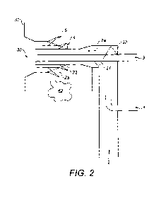
Figure 2 shows how the principles of the invention might be applied to a
burner of
the type illustrated in Figure 1.
A supply tube 1 carrying a concentrated stream of pulverous solid fuel and a
small
amount of transport gas in dense phase is introduced into a larger tube 2
carrying
the primary oxidant to the burner. Figure 2 shows a typical arrangement for
the
dense phase solid fuel injection into the primary stream and its subsequent
mixing
at the burner entry.
In a typical "dense phase" suitable for application of the principles of the
invention,
the transport gas stream could be air, inert gas, or a gas mixture containing
up to
21%v/v oxygen, including flue gas. Typically the mass ratio of solid fuel to
gas
would be of the order of 5:1.
CA 02881477 2015-02-05
WO 2013/030533
PCT/GB2012/052011
A suitable primary oxidant stream for application of the principles of the
invention
could be air or a gas mixture, including flue gas, containing oxygen, for
example air
for air firing, or a mixture of recycled flue gas and oxygen for oxyfuel
firing. The
5 concentration of oxygen in the primary stream is preferably in the range
10 to
35%v/v.
Because mixing between two parallel streams is poor, especially when their
velocities are similar, a suitable mixing device and preferably a static
mixing device
10 is introduced. Conveniently in this embodiment the scroll casting 21,
shown at the
solid fuel and primary oxidant entry to the burner 22, serves as a static
mixing
device. The scroll 21 provides an obstruction to the inlet flow, and imparts a
swirling motion. In this embodiment there is also a 90 change in direction
between
an axial flow direction for the primary supply flow 2 and an axial flow
direction for
15 the primary flow within the burner 2a which further enhances the mixing
of the
solid fuel and primary oxidant.
Advantageously therefore in this embodiment a static mixing device is employed
which was already present in the direct fired design. However, the invention
encompasses additionally or alternatively the provision of specific to purpose
static
and/ or other mixing devices in the primary stream upstream of or at or about
the
inlet to the burner.
At the outlet of the scroll 21 the solid fuel and oxidant are well mixed in a
controlled
fashion, giving the desired solid fuel concentration distribution to promote
stable
combustion. The mixture forms a primary flow 2a through a primary tube to a
burner outlet 30 in a furnace wall 31 in familiar manner.
It is a particular advantage of the invention that it can be applied to low-
NOx
pulverized coal burners following general known design principles without
major
additional modification. Thus, the remainder of the burner, as illustrated
CA 02881477 2015-02-05
WO 2013/030533
PCT/GB2012/052011
16
schematically, may include in any suitable combination those features of the
prior
art burner illustrated in figure 1.
For example the illustrated burner comprises secondary and tertiary conduits 4
and
5 for introduction of supplies of secondary and tertiary oxidant gas, for
example air
for air firing, or a mixture of recycled flue gas and oxygen for oxyfuel
firing.
For example the illustrated burner comprises a core tube 3 about which the
primary
conduit is annularly disposed. The core tube may be used to supply further
oxidant
gases or may include an ignition lance for example coaxially arranged in the
core
tube.
The ignition zone stoichiometry at the outlet of a static mixing device in an
embodiment of the invention would be preferably in the range 0.1 to 0.3 and
for
example about 0.2.
The benefit of the invention is that, by the use of a combination of a dense
phase fuel
inlet pipe and a suitable flow mixing device in the primary flow and in
particular a
suitable static mixing device, the process conditions (i.e. the solid
concentration and
ignition zone stoichiometry) may be modified to create conditions that favour
the
ignition of the solid fuel and thereby enhance the flame stability in the
burner; this
characteristic leads to improved operational flexibility of the low NOx burner
by
allowing it to be used over a wide range of load, and ensuring that flame
stability is
robust with respect to the instantaneous variations in solid fuel feed rate as
observed in practical combustion systems. Additionally the mixture temperature
is
maintained at a level lower than the devolatilisation initiation temperature
to
ensure that uncontrolled burning does not occur within the combustion
equipment
hardware.
In accordance with the invention a solid fuel entry located immediately
upstream of
a mixer is thus used to deliver a controlled mixture of solid fuel and primary
oxidant
containing sufficient oxygen to sustain combustion (including when the fuel
flow is
CA 02881477 2015-02-05
WO 2013/030533
PCT/GB2012/052011
17
subject to fluctuation), and at a temperature lower than the devolatilisation
initiation temperature.