Note : Les descriptions sont présentées dans la langue officielle dans laquelle elles ont été soumises.
CA 02882901 2015-02-25
WO 2014/033605 PCT/1B2013/056841
1
ENVIRONMENT AND USE MONITORING SYSTEM FOR ADVANCED LIFE
SUPPORT DEVICES
[ 0001] The invention relates generally to an improved apparatus and method
for
capturing information related to the environmental conditions and use
experienced by a
medical device. The information is used to modify the protocol for maintaining
the
medical device if necessary. In an illustrated embodiment, the invention is
incorporated
with an external defibrillator having a built-in self testing routine.
Information is
collected and conveyed to a central computer. The central computer may further
integrate
the use information from a number of similar devices. If necessary, the
central computer
adjusts the self testing routine or inspection protocol based on the
information.
[ 0002] Real world environmental conditions such as temperature, humidity,
condensation, shock, and vibration have been known for some time to be
directly related
to product reliability issues. Standard acceleration models have been used to
simulate real
world conditions for the purpose of improving product designs and for reducing
field
failures. However, these acceleration models merely simulate real world
conditions.
Because real world conditions are often different from the simulation, the
models are
error-prone.
[ 0003] Reliability is especially important in the case of medical
products, where a failure
during use can have catastrophic consequences to the patient and/or the user.
For this
reason, many existing medical devices automatically record a history of use
for later
retrieval and analysis. The use history can be used by the manufacturer to
improve later
product designs, to modify device operating protocols, and sometimes to
initiate
corrective actions in the deployed device population. Internal use histories
may also be
CA 02882901 2015-02-25
WO 2014/033605 PCT/1B2013/056841
2
supplemented with manual logs filled out by the user.
[ 0004] One prior art invention which automatically adjusts a self-test in
accordance with
temperature changes near the device is described in U.S. Patent 5,964,786,
entitled
"Environment-Responsive Method for Maintaining an Electronic Device." The
patent is
incorporated herein by reference. The defibrillator described therein utilizes
an internal
self-testing protocol in which the self-test schedule is automatically
adjusted based on
changes in the device temperature.
[ 0005] The existing methods for exploiting such real-world use information
are sub-
optimal. Internal use histories must await the return of the product either to
the medical
administrator or the manufacturer for retrieval. The methods of retrieval are
often
difficult, invasive, limited in sample size, and delayed for long periods of
time from the
time of use. Manual records can also be error prone due to user bias in the
knowledge that
the particular device is being monitored. For this reason, an improved method
and
apparatus are needed to timely collect and respond to the use environment
experienced by
the population of medical devices.
[ 0006] Similarly, what is needed is an improved method for maintaining a
medical
device, one which is responsive to the particular environment in which the
device is used.
For example, external defibrillators are exposed to a wide range of use
environments.
Some defibrillators are used in a simple hospital environment, where
temperature and
other conditions are relatively constant and where the defibrillator is
relatively stationary.
Other defibrillators of the exact same model, however, are deployed in mobile
environments such as Emergency Medical Services (EMS) vehicles, fire trucks,
or
military first aid, where the defibrillators are exposed to extremely harsh
environmental
CA 02882901 2015-02-25
WO 2014/033605 PCT/1B2013/056841
3
conditions and rough handling. A method of adjusting the self-testing and
maintenance
protocols according to the use environment would improve the device
reliability, while
also avoiding unnecessary maintenance activities. In addition, adjusting the
internal self-
testing protocol would optimize battery life by avoiding aggressive self-
testing activities
that may be unnecessary for a benign use environment.
[ 0007] In accordance with the principles of the present invention, an
improved device
and method for monitoring the use history of a medical device is described.
The
monitoring may comprise use and environment information, which can in turn be
used to
provide customized preventive maintenance feedback to the device. Thus, the
invention
incorporates mission-critical data and architecture, in particular for
defibrillators and
other advanced life support devices, which monitors in real-time or near real-
time before
the device fails, in order to provide customized preventive maintenance
feedback to the
end user. This data would be also used to enhance future product designs.
[ 0008] It is another object of the invention to describe a system which
incorporates a
medical device, or plurality of medical devices, each in communication with a
central
computer. The system is operable to compare environmental data and operating
data
against a predictive maintenance model, and to predict a time to failure of
the device
based on the comparison. The system is further operable to provide a feedback
to the
device according to the comparison. The system may also be enabled to adjust
the
predictive maintenance model based on the collected use history.
[ 0009] A particular object of the invention is to describe a network for
the collection of
real-time or near real-time mission critical data and environmental data from
a population
of medical devices. The collection is for the purpose of developing predictive
failure
CA 02882901 2015-02-25
WO 2014/033605 PCT/1B2013/056841
4
models over the entire product population so that customized preventive
maintenance
feedback can be given to the end user. In addition, the collection can be used
to enhance
future product designs for defibrillators and other advanced life support
devices.
[ 0010] It is yet another object of the invention to describe an improved
method for
monitoring the use history of a medical device, and for using the monitoring
to adjust an
operational condition of the medical device based on a comparison with a pre-
determined
maintenance model. The method can be applied in quiescent periods so as not to
interrupt
critical care to the patient.
[ 0011] Exemplary embodiments according to the present disclosure are
further described
herein below with reference to the appended figures. While some exemplary
embodiments may be described separately from one another (e.g., for ease of
presentation
and understanding), one having ordinary skill in the art shall appreciate in
view of the
teachings herein that such exemplary embodiments can be used independently
and/or in
combination with each other. Indeed, the implementation and use of the
exemplary
embodiments described herein, including combinations and variations thereof,
all of
which are considered a part of the present disclosure, can depend on, e.g.,
particular
clinical and/or field use/application, integration with other related
technologies, available
resources, environmental conditions, etc. Accordingly, nothing in the present
disclosure
should be interpreted as limiting of the subject matter disclosed herein.
[ 0012] The present disclosure will present in detail the following
description of preferred
embodiments which should be considered in view of the appended figures, as
referenced
herein below, for example.
CA 02882901 2015-02-25
WO 2014/033605 PCT/1B2013/056841
[ 0013] FIGURE 1 is an illustration of an external defibrillator for use
with the present
invention.
[ 0014] FIGURE 2 is a block diagram showing the functional components of an
external
defibrillator that may be used to implement the methods of this invention.
[ 0015] FIGURE 3 is a functional block diagram of an external defibrillator
and the
inventive data collection device, with one embodiment of a communications
interface.
[ 0016] FIGURE 4 illustrates the inventive system comprising a plurality of
medical
devices in communication via a cloud computing environment with a central
computer.
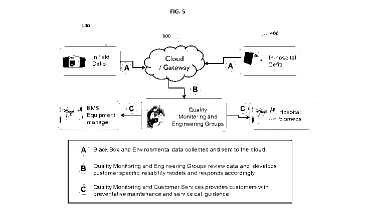
[ 0017] FIGURE 5 illustrates another block diagram of the invention,
illustrating the
information flow between devices and the centralized functions, according to
one
embodiment of the invention.
[ 0018] FIGURE 6 illustrates a flow chart showing one embodiment of the
inventive
method.
[ 0019] The present invention is further described in three main elements
as exemplary
embodiments of the present invention. For example, the first element comprises
an
apparatus that is co-located with the medical device. The apparatus and
medical device
interact to collect the use history of the device, such as button pushes,
detailed hardware
and software error logs, power fluctuations, charge times, and key patient
parameters. In
addition, the apparatus incorporates sensors which collect environmental data
such as
temperature, humidity, condensation, shock, vibration, and location. The
apparatus
further incorporates a communications feature for conveying the data to a
computer for
further analysis.
[ 0020] The second exemplary element of the invention is a communications
pathway to
CA 02882901 2015-02-25
WO 2014/033605 PCT/1B2013/056841
6
the analyzing computer. The computer may be disposed at a central location,
i.e. a central
computer. The communications pathway may be constructed as a network, such as
a
cloud computing network. The network may be disposed to wirelessly collect and
store
patient and other information at a storage location, for future retrieval and
analysis by
authorized users.
[ 0021] The third exemplary element of the invention is for analysis and
feedback. The
use data and environmental data are compared to a predictive maintenance model
which
resides on a computer. If the data departs sufficiently from the model, the
computer may
issue a command to adjust an operational condition of the medical device. If
the
computer is a central computer, the command is communicated to the device via
the
network. The device operations may then be automatically adjusted in some way.
For
example, a self-testing schedule may be adjusted to test the device more often
if it is
subjected to an extreme environment or use schedule. Or a message may be
displayed on
the device to inspect the device more frequently, or even to remove it from
service and
return to the manufacturer. Finally, the data itself may provide a catalyst to
modify the
predictive maintenance model itself, by correlating failure profiles with the
actual device
use model. If, for example, devices fail less often in extremely cold
temperatures than
forecast during design, then the allowable temperature operating range could
be
expanded.
[ 0022] Now turning to the drawings, FIGURE 1 illustrates one embodiment of
a medical
device 10 disposed with a data collection device 100. In the illustrated
embodiment,
medical device 10 is an external defibrillator, such as the Heartstart XL+ TM
manufactured by Philips Healthcare, Andover Massachusetts.
CA 02882901 2015-02-25
WO 2014/033605 PCT/1B2013/056841
7
[ 0023] FIGURE 1 shows data collection device 100 as attached to and
external to device
10. The attachment may be by a clip such that the devices may be detached from
each
other, or may be screwed or permanently affixed together. This configuration
is
advantageous because data collection device 100 can be powered by its own
rechargeable
or replaceable power supply, such that the medical device 10 power supply is
reserved
solely for use in medical treatment events. As illustrated, data collection
device 100 may
optionally include a user output 140 which is a display. User output 140 may
also be
disposed as an indicator light, a readiness indicator, or as an audible
annunciator.
[ 0024] Data collection device 100 may also comprise a wireless transceiver
130.
Transceiver 130 is preferably disposed to transmit use data collected by the
device 10
and/or monitor 100 as well as environmental data collected by monitor 100.
Transceiver
130 may also be disposed to receive instructions which automatically modify an
operational status of device 10. In consequence of the receiving, a message or
indication
may be placed on user output 140 or on a user output of device 10. A message
may
indicate that an additional inspection of the device is necessary, that the
device should be
removed from service, or that the device should be returned to the
manufacturer.
Preferably, the indication occurs prior to any failure of device 10. In
another
embodiment, a self-testing protocol residing within device 10 is adjusted via
monitor 100
to reflect the actual operating environment experienced by the device.
[ 0025] In an alternate embodiment, data collection device 100 is
incorporated within the
device 10 housing in order to realize cost and simplicity benefits of sharing
common
components, such as displays, controls, annunciators, or power sources.
CA 02882901 2015-02-25
WO 2014/033605 PCT/1B2013/056841
8
[ 0026] Turning now to FIGURE 2, shown is a block diagram showing an
external
defibrillator that may be used to implement the methods of this invention.
Some of the
FIGURE 2 elements shown bear only indirectly to the present invention, and are
included
solely to show one context in which the invention may operate.
[ 0027] Device 10, here exemplified as an external defibrillator is shown
in FIGURE 2.
While defibrillators are particularly appropriate for implementing this
invention, the
invention is not limited to use in defibrillators. Defibrillators provide
electrotherapy
treatment for sudden cardiac arrest by providing a high-voltage shock through
a patient's
heart via externally-applied electrodes 37. An electrical connector 36 permits
connection
of disposable electrodes to device 10.
[ 0028] In the defibrillator shown in FIGURE 2, battery capacity tests are
run daily as part
of a suite of automatic self-tests via power management block 32, and the
results are
recorded in a device history log (DHL) stored in memory 14. Other device 10
functions
are tested or measured at status measurement 112 and recorded in memory 14.
Device 10
also periodically records temperature into the DHL via temperature sensors 9
or 31.
Control functions of device 10 are distributed among an main processor unit
(MPU) 2
and two gate arrays 4 and 6. Gate array 6 also performs some of the functions
of the self-
test initialization generation.
[ 0029] The self-testing features of device 10 extend to connected
accessories as well. The
defibrillator, for example, may include pre-connected disposable electrodes 37
which are
checked for continuity by the self-testing protocol. Advanced
defibrillator/monitors, for
example, may include a module for monitoring electrocardiograms (ECG), blood
oxygen
(5P02) or non-invasive blood pressure (NIBP), either hardwired to the
defibrillator or
CA 02882901 2015-02-25
WO 2014/033605 PCT/1B2013/056841
9
wirelessly connected. Device 10 is envisioned to include features that
automatically
check these features, and/or their connecting cables, on a periodic basis.
[ 0030] Gate array 6 may monitor "wake-up" conditions, such as an out-of-
bounds
temperature reading at temperature sensor 31, the press of an on/off button 30
by the
user, or a detected drop/shock experienced by the device. Gate array 6 may
also blink a
status ready indicator light 28 or beeper 19 periodically to indicate the
operational status
of the device 10. Gate array 6 may also track the number of button presses,
turn-on/off,
shocks delivered, and other user actions at counter 7, also stored in memory
14.
[ 0031] MPU 2 acts as the general controller of device 10 when it is
operating outside of
the standby mode. MPU 2 controls the decision whether to shock via block 26.
MPU 2
also provides user control functions for a device display 18 via contrast
button 8. Gate
array 4 provides display 18 functionality and issues aural commands via
speaker 20.
[ 0032] Taken together, the components of device 10 form a self-test
circuit for sensing a
fault in the device. The components also provide visual and audio outputs for
indicating
the status of the device and for issuing instructions to the user. The
controller functions to
collect and record operating data, and to execute software instructions for
conducting the
self-test.
[ 0033] The operation of device 10 is also influenced by data collection
device 100 via
port 16. Port 16 operates to communicate use data, such as stored in the DHL,
from
device 10 to data collection device 100. Port 16 also operates to communicate
instructions and environmental data from monitor 100 to device 10. The
instructions are
used by MPU 2 to adjust device 10 operations, such as to display a message on
display 18
or to adjust a timing or test parameter of the self-testing algorithm.
CA 02882901 2015-02-25
WO 2014/033605 PCT/1B2013/056841
[ 0034] FIGURE 3 illustrates a functional block diagram of the data
collection device 100
disposed as interfaced with device 10. Port 16 is shown as a bidirectional
communication
port which interfaces with monitor 100. The interface can be any commonly
known in the
art, such as infrared, radio, Bluetooth TM or b-field communications
protocols.
[ 0035] Device 100 is comprised of several functional circuits. One or more
environmental sensors 110 operate to collect environmental data, such as
temperature,
humidity, condensation, shock, or vibration. Another sensor 110 embodiment is
a GPS
sensor which provides location data of the device. One or more of these
sensors can be
disposed within device 10 as well.
[ 0036] Environmental data collected by sensor(s) 110 is stored in a data
collection device
memory 120. The data is preferably correlated in time, and also is preferably
combined
with operating data obtained from the medical device 10 via port 16.
[ 0037] The environmental data and operating data is disseminated via
wireless
transceiver 130 in a preferred embodiment. Transmission of the data is
preferably on a
scheduled basis. Transceiver 130 may also be operable to receive instructions
from a
remote transmitter, such as an instruction to modify a device maintenance
routine. The
received instruction is communicated to device 10 via port 16.
[ 0038] An optional user output 140 may be disposed on the outside of data
collection
device 100, for conveying information to the user about the device. Output 140
may be
responsive to the instructions to provide a message or indication light to the
user to
provide some preventive maintenance feedback which is in addition to the
previously-
provided maintenance protocol. Output 140 may also be disposed as a warning
light or
an audible beeper to attract the attention of maintenance personnel to a
message
CA 02882901 2015-02-25
WO 2014/033605 PCT/1B2013/056841
11
displayed on device 10 itself.
[ 0039] All functions of data collection device 100 are controlled by a
controller 150,
which is in communication with each of the sensor 110, memory 120, output 140,
port
16, and wireless transceiver 130. Controller 150 may communicate any received
instructions to medical device 10 for the purpose of causing an alteration in
the self-test
protocol of device 10, or to display a message there. Power supply 160
provides power,
independent of device 10, to the data collection device 100.
[ 0040] FIGURE 4 illustrates a system for monitoring the use history and
the
environmental history of one or more medical devices, each device having a
data
collection device 100, 400, 500. The medical devices are preferably similar in
configuration to each other, such that the same preventive maintenance model
would
apply to each device. Each medical device and associated data collection
device 100, 400,
500 are disposed as described above and as shown in FIGURES 1 through 3.
Namely,
each of the medical devices has a self-test circuit for sensing a fault in the
device and a
communications path for communicating with a data collection device. Memory in
each
data collection device is operable to record operating data from the medical
device and
environmental data collected by an environmental sensor in the monitor. Each
monitor
has a wireless transceiver operable to transmit and receive data. Each of the
monitors is
controlled by a controller, which causes the monitor to transmit the
environmental and
operating data during periods prior to a sensed fault in the attached medical
device.
[ 0041] The FIGURE 4 system includes a communications pathway, such as a
cloud
communication environment 300, which links each monitor 100, 400, 500 with a
remote
second memory 200. Second memory 200 receives and stores environmental data
and
CA 02882901 2015-02-25
WO 2014/033605 PCT/1B2013/056841
12
operating data from each of the devices, for later analysis and comparison
against a
preventive maintenance model. A central computer 210 is further arranged to
access the
data stored in memory 200, preferably via cloud communication environment 300
as
well. Central computer 210 executes predictive maintenance model software,
which
compares the environmental and operating data obtained from memory 200 with
parameters in the maintenance model.
[ 0042] The predictive maintenance model may be configured to compare real-
world
environmental and operating conditions as experienced by the devices with
design
parameters established during design of the devices. The output of the
comparison is
preferably a prediction of the time to failure of the device, and perhaps the
mode of
failure as well.
[ 0043] If the predicted time to failure falls within a pre-determined
limit, central
computer 210 may transmit an alert back to the data collection device 100,
400, 500 via
the cloud communication environment 300. The particular data collection device
may
then communicate with the attached medical device to cause the device to
adjust a
parameter in its self-test circuit for the purpose of enhancing the self-
test(s)
corresponding to the impending device failure. In addition, the data
collection device may
issue or cause to issue a user alert on a user output disposed on the monitor
or the device.
The user alert may comprise an instruction to alter the existing preventive
maintenance
protocol or to remove the device from service.
[ 0044] By incorporating real-world experience data from multiple devices
and data
collection devices that are operating in a variety of environments, the FIGURE
4 system
can realize additional advantages. First, the incidence of failure or not with
regards to
CA 02882901 2015-02-25
WO 2014/033605 PCT/1B2013/056841
13
environments at the bounds of the predictive maintenance model limits may
allow for the
adjustment of the model in order to improve failure predictions. Also, the
data may allow
for improved characterization of the medical device performance within certain
operating
environments. For example, a particular device may be shown to perform better
in high
use environments than in high standby environments. With the improved
knowledge of
how the device operates in certain environments, the predictive maintenance
model can
also be refined and improved by adjusting the limit parameters for devices
identified as
operating in those particular environments.
[ 0045] FIGURE 5 illustrates the utility of the networked system of FIGURE
4. As
illustrated there, devices and monitors 100 and 400 communicate via a cloud
communication environment 300 to "Quality Monitoring and Engineering Groups"
having a central computer 210. The monitoring and engineering groups are
enabled by
the invention to analyze the operating history and environment for the devices
in real-
time or near-real-time. The analysis output is preferably a predicted time to
failure for
each device, as well as the failure mode. In addition, the analysis output
preferably
provides supplemental preventive maintenance recommendations for each device
customized to the environment/history. The recommendations may be changes to
the
scheduled self-testing, guidance for additional manual checks by the owner,
requests to
remove the device from service pending a visit from a service provider, or
requests to
return the device to the manufacturer for servicing. Each of these
recommendations is
preferably provided to customers such as "Hospital Biomeds" or "EMS Equipment
Managers" prior to the actual failure of the device in the field.
CA 02882901 2015-02-25
WO 2014/033605 PCT/1B2013/056841
14
[ 0046] The system may also be operable to compare the operating and
environmental
conditions of the device population to experiential failure rates. The
comparison could
subsequently be used by the manufacturer to develop specialized
recommendations for
use in new products, or to adjust a warranty package according to the
particular user
and/or region of the world which treats the device more harshly.
[ 0047] FIGURE 6 is a flow chart of a method for monitoring the use history
of a medical
device by comparing the use history to a preventive maintenance model (PMM).
The
method further provides a change to an operating condition of the medical
device based
on the comparison. The method, when applied to a plurality of devices, may
further
provide a change to the PMM upon which the comparison is based. The systems
and
apparatus as described previously act in concert to realize the benefits of
the method.
[ 0048] The initial steps of the method provide one or more data collection
devices at step
1000 which collect at step 1100 operational data and environmental data about
the
medical devices to which the data collection devices are attached. The data is
transmitted
at step 1200 to a central computer for analysis. At step 1300, the central
computer
compares the operational data and the environmental data with a pre-determined
PMM.
The comparison may indicate that the underlying device is at risk of impending
(or
premature) failure by determining that the data place the device history
outside the
bounding parameters of the PMM model. If so, decision step 1400 directs the
method
toward corrective action starting at step 1500. If the device is determined
not to be at risk
of premature failure, the data is stored at step 1600 for use in subsequent
comparison with
like devices or for refining the PMM.
CA 02882901 2015-02-25
WO 2014/033605 PCT/1B2013/056841
[ 0049] Method step 1500 applies the data and comparison to the
determination as to a
modified or recommended operational condition for the device, for the purpose
of
ensuring that the device remains reliable and functional in the field. The
types of
modification, as described previously, could be changes to the scheduled self-
testing,
guidance for additional manual checks by the owner, requests to remove the
device from
service pending a visit from a service provider, or requests to return the
device to the
manufacturer for servicing. The guidance provided to the device owner could be
conveyed by the step 1200 communication pathway at step 1700 or by
conventional
means such as telephone or mail communications. Responsive to the transmission
of the
new conditions to the data collection device, the underlying medical device
operating
condition is changed at step 1800. Preferably the change is completely
automatic so that
the user is not required to take further action.
[ 0050] Step 1900 enables the method to utilize the stored data and
comparisons from a
plurality of devices to refine the PMM. The comparisons, environmental data,
and
operational histories are analyzed, preferably with some additional data
regarding actual
failure rates and modes from devices. If the analysis indicates that the PMM
should be
refined or modified, the method does so.
[ 0051] The feedback and analysis enabled by the invention provide a better
understanding of the actual use and abuse of the underlying device population.
Such
understanding leads to improved designs for the next generation of product. In
addition,
the understanding of different use profiles and environments for the product
enables the
manufacturer to customize preventive maintenance procedures and to better
predict a
time to failure for that particular device.
CA 02882901 2015-02-25
WO 2014/033605 PCT/1B2013/056841
16
[ 0052] The feedback portion of the invention allows the manufacturer to
identify those
customers that subject their devices to harsh conditions. The manufacture can
then
remotely alert the customer to perform more frequent preventive maintenance.
Also, the
invention could alert manufacturer service personnel as to the particular
devices which
are more likely to require a service call. Finally, the manufacturer is in a
better position
to adjust warranty and other service-related costs according to the customer
profile and/or
region which demonstrate harsher treatment of the product.
[ 0053] Modifications to the device, software, and displays as described
above are
encompassed within the scope of the invention. For example, the method may be
accomplished at the data collection device itself if the PMM and computer are
resident
there, thus eliminating the need for method steps 1200 and 1700. Thus, instead
of
transmitting environmental and use data from the monitor as often, the cloud
communication path would periodically transmit updates to the PMM from the
central
computer to the data collection device population. Then the monitors would
compare
their own data against the resident PMM to adjust parameters or notify the
user. When a
particular monitor determines that it has departed by a certain amount from
the PMM,
then it could transmit the stored data back to the central computer, where the
PMM is
adjusted (using that data and data received from many other devices). The
adjusted PMM
is subsequently returned to the monitor as an update.
[ 0054] Also, the appearance and arrangement of the alerts at the device
location may
differ, in type and in appearance. Different maintenance models which are
incorporated
into the central computer, but which perform essentially the same predictive
functions as
described, also fall within the scope of the invention.
CA 02882901 2015-02-25
WO 2014/033605 PCT/1B2013/056841
17
[ 0055] It should be understood that, while the present invention has been
described in
terms of medical applications, the teachings of the present invention are much
broader
and are applicable for non-medical applications and uses. Further, As one
having
ordinary skill in the art will appreciate in view of the teachings provided
herein, features,
elements, components, etc. described in the present disclosure/specification
and/or
depicted in the appended Figures may be implemented in various combinations of
hardware and software, and provide functions which may be combined in a single
element or multiple elements. For example, the functions of the various
features,
elements, components, etc. shown/illustrated/depicted in the Figures can be
provided
through the use of dedicated hardware as well as hardware capable of executing
software
in association with appropriate software. When provided by a processor, the
functions
can be provided by a single dedicated processor, by a single shared processor,
or by a
plurality of individual processors, some of which can be shared and/or
multiplexed.
Moreover, explicit use of the term "processor" or "controller" should not be
construed to
refer exclusively to hardware capable of executing software, and can
implicitly include,
without limitation, digital signal processor ("DSP") hardware, memory (e.g.,
read only
memory ("ROM") for storing software, random access memory ("RAM"), non
volatile
storage, etc.) and virtually any means and/or machine (including hardware,
software,
firmware, combinations thereof, etc.) which is capable of (and/or
configurable) to
perform and/or control a process.
[ 0056] Moreover, all statements herein reciting principles, aspects, and
embodiments of
the invention, as well as specific examples thereof, are intended to encompass
both
structural and functional equivalents thereof. Additionally, it is intended
that such
CA 02882901 2015-02-25
WO 2014/033605 PCT/1B2013/056841
18
equivalents include both currently known equivalents as well as equivalents
developed in
the future (e.g., any elements developed that can perform the same or
substantially
similar function, regardless of structure). Thus, for example, it will be
appreciated by one
having ordinary skill in the art in view of the teachings provided herein that
any block
diagrams presented herein can represent conceptual views of illustrative
system
components and/or circuitry embodying the principles of the invention.
Similarly, one
having ordinary skill in the art should appreciate in view of the teachings
provided herein
that any flow charts, flow diagrams and the like can represent various
processes which
can be substantially represented in computer readable storage media and so
executed by a
computer, processor or other device with processing capabilities, whether or
not such
computer or processor is explicitly shown.
[ 0057] Furthermore, exemplary embodiments of the present invention can
take the form
of a computer program product accessible from a computer-usable and/or
computer-
readable storage medium providing program code and/or instructions for use by
or in
connection with, e.g., a computer or any instruction execution system. In
accordance
with the present disclosure, a computer-usable or computer readable storage
medium can
be any apparatus that can, e.g., include, store, communicate, propagate or
transport the
program for use by or in connection with the instruction execution system,
apparatus or
device. Such exemplary medium can be, e.g., an electronic, magnetic, optical,
electromagnetic, infrared or semiconductor system (or apparatus or device) or
a
propagation medium. Examples of a computer-readable medium include, e.g., a
semiconductor or solid state memory, magnetic tape, a removable computer
diskette, a
random access memory (RAM), a read-only memory (ROM), flash (drive), a rigid
CA 02882901 2015-02-25
WO 2014/033605 PCT/1B2013/056841
19
magnetic disk and an optical disk. Current examples of optical disks include
compact
disk ¨ read only memory (CD-ROM), compact disk ¨ read/write (CD-R/W) and DVD.
Further, it should be understood that any new computer-readable medium which
may
hereafter be developed should also be considered as computer-readable medium
as may
be used or referred to in accordance with exemplary embodiments of the present
invention and disclosure.
[ 0058] Having described preferred and exemplary embodiments of systems,
devices and
methods in accordance with the present invention (which embodiments are
intended to be
illustrative and not limiting), it is noted that modifications and variations
in/to such
exemplary embodiments can be made by persons skilled in the art in light of
the
teachings provided herein (including the appended Figures). It is therefore to
be
understood that such changes which can be made in/to the preferred and
exemplary
embodiments of the present disclosure are within the scope of the present
invention and
the exemplary embodiments disclosed herein.