Note : Les descriptions sont présentées dans la langue officielle dans laquelle elles ont été soumises.
CA 02883731 2015-03-03
1
DESCRIPTION
DEVELOPING DEVICE, DEVELOPING CARTRIDGE,
ROTATIONAL FORCE TRANSMITTING PART
AND
ELECTROPHOTOGRAPHIC IMAGE FORMING APPARATUS
This application is a divisional of Canadian
Patent Application No. 2,728,942 filed August 27, 2009.
[TECHNICAL FIELD]
The present invention relates to a developing
device, a developing cartridge, a rotational force
transmitting part, and an electrophotographic image
forming apparatus with which the developing cartridge
is used.
The electrophotographic image forming apparatus
forms an image on a recording material using an
electrophotographic image forming process. The
electrophotographic image forming apparatus includes
an electrophotographic copying machine, an
electrophotographic printer (a laser beam printer, an
LED printer), and so on.
In addition, the developing cartridge is
dismountably mounted to a main assembly of the
electrophotographic image forming apparatus, and
develops an electrostatic latent image formed on the
electrophotographic photosensitive member. By a user
exchanging the developing cartridge, a maintenance
CA 02883731 2015-03-03
2
operation of the image forming apparatus is carried
out in effect.
[BACKGROUND ART]
Conventionally, in the electrophotographic
image forming apparatus, when the electrostatic latent
image formed on the electrophotographic photosensitive
member (photosensitive drum) of a drum configuration
is developed using the developing cartridge, the
operation is carried out as follows.
The developing cartridge is provided with a
gear, and is engaged with a gear provided in the main
assembly of the electrophotographic image forming
apparatus. A rotational force of a motor provided in
the main assembly is transmitted to a developing
roller through the gear provided in the main assembly,
and the gear provided in the developing cartridge side.
By this, such a type of rotating the developing roller
is known (Japanese Laid-open Patent Application 2003-
202727).
In a known color electrophotographic image
forming apparatus, a developing rotary member rotated
in the state that a plurality of developing devices
are mounted is provided in a main assembly. In this
device, in order to transmit the rotational force from
the main assembly to the developing cartridge the
following structures are known. The a main assembly
CA 02883731 2015-03-03
side coupling provided in the main assembly, and a
developing device s'de coupling of the developing
device mounted to the developing rotary member are
connected with each other. By this, the rotational
force is transmitted from the main assembly to the
developing device. And, in connecting the main
assembly side coupling, and the developing device side
coupling with each other, the main assembly side
coupling is once retracted in the device so that it
does not interfere with the movement of the developing
rotary member. Then, the developing rotary member is
moved to move a predetermined developing device toward
the main assembly side coupling. Thereafter, the main
assembly side coupling retracted using a moving
mechanism such as a solenoid is moved toward the
developing device side coupling. By this, both of the
couplings are connected with each other. And, the
rotational force of the motor provided in the main
assembly is transmitted to the developing roller
through the main assembly side coupling, and the
developing device side coupling. By this, the
developing roller is rotated. Such a type is known
(Japanese Laid-open Patent Application common 11-
015265).
However, according to the conventional
structure described in the Japanese Laid-open Patent
Application 2003-202727, a drive connecting portion of
CA 02883731 2015-03-03
4
the main assembly, and the developing device is a
gear-to-gear type. For this reason, it is difficult to
prevent a rotation Jnevenness of the developing roller.
On the other hand, in the structure described
in Japanese Laid-open Patent Application Hei 11-015265,
as has been described hereinbefore, the main assembly
side coupling is once retracted. In transmitting the
rotational force, it is necessary that the retracted
main assembly side coupling is moved toward the
developing device side coupling.
Then, it is necessary that a mechanism for
moving the main assembly side coupling toward the
developing device side coupling is provided in the
main assembly.
[DISCLOSURE OF THE INVENTION]
The principal object of the present invention
is to provide a developing device, a developing
cartridge, and an electrophotographic image forming
apparatus usable with the developing device or the
developing cartridge, which are improved to avoid the
problem of the prior art.
Another object of the present invention is to
provide a rotational force transmitting part usable
with such a developing cartridge.
A further object of the present invention is to
maintain a coupling member at a pre-engagement angular
CA 02883731 2015-03-03
position (second angular position) even in the case
where the developing cartridge is in a free state.
Therefore, the coupling member is prevented from
unintentional movement in transporting the developing
5 cartridge, for example.
A further object of the present invention is to
provide a rotational force transmitting part usable
with such a developing cartridge. A further object of
the present invention is to provide a usable
electrophotographic image forming apparatus with such
a developing cartridge.
A further object of the present invention is to
provide a developing device (developing cartridge)
which is usable with the main assembly which not
provided with the mechanism for moving the main
assembly side coupling member in the axial direction
thereof by a solenoid mechanism.
= A further object of the present invention is to
provide a developing device (developing cartridge),
wherein the coupling member provided on the developing
device (developing cartridge) is engaged with the
drive shaft by moving the developing device
(developing cartridge) in the direction substantially
perpendicular to the axial direction of the drive
shaft relative to the main assembly.
A further object of the present invention is to
provide an electrophotographic image forming apparatus
CA 02883731 2015-03L03
6
usable with such a developing device (developing
cartridge).
A further object of the present invention is to
provide a developing device (developing cartridge),
wherein the engagement with the drive shaft is carried
out by the movement in the direction substantially
perpendicular to the axial direction of the drive
shaft provided in the main assembly of the
electrophotographic image forming apparatus.
A further object of the present invention is to
provide a rotational force transmitting part usable
with such a developing device (developing cartridge).
A further object of the present invention is to
provide an electrophotographic image forming apparatus
usable with such a developing device (developing
cartridge).
A further object of the present invention is to
provide a developing device (developing cartridge),
wherein the developing roller is rotated smoothly as
compared with the case in which a driving connection
between the main assembly, and the developing device
(developing cartridge) is carried out by the gear-to-
gear transmission.
A further object of the present invention is to
provide a rotational force transmitting part usable
with such a developing cartridge.
A further object of the present invention is to
CA 02883731 2015-03-03
7
provide an electrophotographic image forming apparatus
usable with such a developing device (developing
cartridge).
A further object of the present invention is to
provide a developing device (developing cartridge),
wherein the developing roller which can be engaged
with the drive shaft in the direction substantially
perpendicular to the axial direction of the drive
shaft provided in the main assembly is rotated
smoothly.
A further object of the present invention is to
provide a rotational force transmitting part usable
with such a developing device (developing cartridge).
A further object of the present invention is to
provide an electrophotographic image forming apparatus
usable with such a developing device (developing
cartridge).
A further object of the present invention is to
provide a developing device (developing cartridge)
which is engaged and disengaged in the direction
substantially perpendicular to the axial direction
relative to the drive shaft provided in the main
assembly of the electrophotographic image forming
apparatus by rotation of a rotary member.
A further object of the present invention is to
provide a rotational force transmitting part usable
with such a developing device (developing cartridge).
CA 02883731 2015-03-03
8
A further object of the present invention is to
provide an electrophotographic image forming apparatus
usable with such a developing device (developing
cartridge).
A further object of the present invention is to
provide the developj_ng device (developing cartridge)
which is engaged and disengaged in the direction
substantially perpendicular to the axial direction of
the drive shaft relative to the drive shaft provided
in the main assembly by the movement (rotation) of a
movable member (rotary member) and which rotates the
developing roller smoothly.
A further object of the present invention is to
provide a rotational force transmitting part usable
with such a developing device (developing cartridge).
A further object of the present invention
provides an electrophotographic image forming
apparatus usable with such a developing device
(developing cartridge).
A further object of the present invention is to
provide a developing device (developing cartridge),
wherein the coupling member is maintained in the pre-
engagement angular position in the state that it is
stabilized.
A further object of the present invention is to
provide a rotational force transmitting part usable
with such a developing device (developing cartridge).
CA 02883731 2015-03-03
9
A further object of the present invention is to
provide an electrophotographic image forming apparatus
usable with such a developing device (developing
cartridge).
A further object of the present invention is to
provide a developing device (developing cartridge),
wherein the coupling member is assuredly maintained in
the pre-engagement angular position.
A further object of the present invention is to
provide a rotational force transmitting part usable
with such a developing device (developing cartridge).
A further object of the present invention is to
provide an electrophotographic image forming apparatus
usable with such a developing device (developing
cartridge).
A further object of the present invention is to
provide a developing device (developing cartridge)
which is applicable to the case where the developing
device (developing cartridge) moves in the direction
perpendicular to the axial direction of the drive
shaft provided in the main assembly in response to the
movement (rotation) of the movable member (developing
rotary member) which has a swinging rotation axis.
A further object of the present invention is to
provide a developing device (developing cartridge),
wherein even in such a case, the engagement and
disengagement relative to the drive shaft are assured,
CA 02883731 2015-03-03
and the developing roller is rotated smoothly.
A further object of the present invention is to
provide a rotational force transmitting part usable
with such a developing device (developing cartridge).
5 A further object of the present invention is to
provide an electrophotographic image forming apparatus
usable with such a developing device (developing
cartridge).
A further object of the present invention
10 provides a developing device to which a developing
roller which is rotating can be contacted to the
electrophotographic photosensitive member.
A further object of the present invention is to
provide an electrophotographic image forming apparatus
usable with such a developing device.
A further object of the present invention is to
provide a rotational force transmitting part usable
with such a developing device.
In addition, a further object of the present
invention is to provide a developing device, wherein
even if the drive shaft fixed so as not to move in the
direction substantially perpendicular to the direction
of the axis of the drive shaft is used, the developing
roller in the rotatjng state and the
electrophotographic photosensitive member can be
contacted to each other.
A further object of the present invention is to
CA 02883731 2015-03-03
11
provide an electrophotographic image forming apparatus
usable with such a developing device.
A further object of the present invention is to
provide a rotational force transmitting part usable
with such a developing device.
According to an aspect of the present invention,
there is provided a developing device usable with an
electrophotographic image forming apparatus, said
apparatus including a driving shaft rotatable by a
motor and having a rotating force applying portion,
and a movable member, said developing device being
mountable to the movable member, and said developing
device being movable in a direction substantially
perpendicular to an axial direction of the driving
shaft in response to movement of the movable member in
one direction with said developing device mounted to
the movable member, wherein said driving shaft is not
movable in a direction perpendicular to an axix
thereof, said developing device comprising i) a
developing roller for developing an electrostatic
latent image formed on an electrophotographic
photosensitive drum, said developing roller being
rotatable about an axis, wherein said developing
roller is contacted to and separated from said
electrophotographic photosensitive member drum in
response to movement of said movable member; and ii) a
coupling member for transmitting a rotating force to
CA 02883731 2015-03-03
12
said developing roller, said coupling member including,
a rotating force receiving portion engageable with the
rotating force applying portion to receive a rotating
force from the driving shaft, and a rotating force
transmitting portion for transmitting the rotating
force received through said rotating force receiving
portion to said developing roller, said coupling
member being capable of taking a rotational force
transmitting angular position for transmitting the
rotational force for rotating said developing roller
to said developing roller, a pre-engagement angular
position which is taken before said coupling member is
engaged with the rotating force applying portion and
in which said coupling member is inclined away from
said rotational force transmitting angular position,
and a disengaging angular position which is taken for
said coupling member to disengage from the driving
shaft and in which said coupling member is inclined
away from the rotational force transmitting angular
position in a direction opposite to said pre-
engagement angular position, wherein in response to a
movement of said developing device when the movable
member moves in said one direction, said coupling
member moves from the pre-engagement angular position
to the .rotational force transmitting angular position,
and wherein when the movable member makes a further
movement in said one direction, in response to the
CA 02883731 2015-03-03
13
further movement, said coupling member is moved from
said rotational force transmitting angular position to
said disengaging angular position to disengage said
coupling member from said driving shaft, and wherein
said developing roller is contacted to said
electrophotographic photosensitive member in response
to the movement of said developing device in a state
that developing roller is being rotated through
engagement between said coupling member and said
rotating force applying portion.
According to another aspect of the present
invention, there is provided an electrophotographic
image forming apparatus for forming an image on a
recording material, said electrophotographic image
forming apparatus comprising i) a driving shaft
rotatable by a motor and having a rotating force
applying portion, wherein said driving shaft is not
movable in a direction perpendicular to an axix
thereof; ii) a movable member; iii) a developing
device which is movable in a direction substantially
perpendicular to an axial direction of the driving
shaft in response to movement of the movable member in
a state that developing device is mounted to said
movable member, in response to the moment of said
movable member, said developing roller including a
developing roller for developing an electrostatic
latent image formed on an electrophotographic
CA 02883731 2015-03-03
14
photosensitive drum, said developing roller being
rotatable about an axis, wherein said developing
roller is contacted to and separated from said
electrophotographic photosensitive member drum in
response to movement of said movable member; iv) a
coupling member for transmitting a rotating force to
said developing roller, said coupling member including,
a rotating force receiving portion engageable with the
rotating force applying portion to receive a rotating
force from the driving shaft, and a rotating force
transmitting portion for transmitting the rotating
force received through said rotating force receiving
portion to said developing roller, said coupling
member being capable of taking a rotational force
transmitting angular position for transmitting the
rotational force for rotating said developing roller
to said developing roller, a pre-engagement angular
position which is taken before said coupling member is
engaged with the rotating force applying portion and
in which said coupling member is inclined away from
said rotational force transmitting angular position,
and a disengaging angular position which is taken for
said coupling member to disengage from the driving
shaft and in which said coupling member is inclined
away from the rotational force transmitting angular
position in a direction opposite to said pre-
engagement angular position to disengage from the
CA 02883731 2015-03-03
driving shaft, wherein in response to a movement of
said developing device when the movable member moves
in said one direction, said coupling member moves from
the pre-engagement angular position to the rotational
5 force transmitting angular position, and wherein when
the movable member makes a further movement in said
one direction, in response to the further movement,
said coupling member is moved from said rotational
force transmitting angular position to said
10 disengaging angular position to disengage said
coupling member from said driving shaft, and wherein
said developing roL.er is contacted to said
electrophotographic photosensitive member in response
to the movement of said developing device in a state
15 that developing roller is being rotated through
engagement between said coupling member and said
rotating force applying portion.
According to a further aspect of the present
invention, there is provided a developing device
usable with an electrophotographic image forming
apparatus, said apparatus including a driving shaft
rotatable having a rotating force applying portion,
and a rotatable rotary, said developing device being
movable in a direction substantially perpendicular to
an axial direction of the driving shaft in response to
rotation of said rotary with said developing device
mounted to said rotary, said developing device
CA 02883731 2015-03-03
16
comprising i) a developing roller for developing an
electrostatic latent image formed on an
electrophotographic photosensitive member drum; ii) a
developer accommodating portion for accommodating a
developer for use by said developing roller to
developing the electrostatic latent image; iii) a
coupling member for transmitting a rotating force to
said developing roller in a state that developing
cartridge is mounted to said rotary, said coupling
member including a rotating force receiving portion
for engaging with the rotating force applying portion
to receive said driving shaft the rotating force from
the driving shaft, wherein the driving shaft is not
movable in a direction substantially perpendicular to
an axial direction of said driving shaft; iv) a
regulating member including a regulating portion for
regulating said coupling member at a pre-engagement
angular position before engagement with the driving
shaft, and including a permitting portion for
permitting said coupling member to revolve
substantially; v) an elastic member for elastically
urging said coupling member to position said coupling
member at the regulating portion, wherein when said
rotary rotates, said coupling member moves from the
pre-engagement angular position to a rotational force
transmitting angular position the response to movement
of said coupling member from the regulating portion To
CA 02883731 2015-03-03
17
the permitting portion against an elastic force of
said elastic member by said coupling member contacting
said driving shaft member with movement of said
developing cartridge, and when said rotary further
rotates, said coupling member moves from the
rotational force transmitting angular position to a
disengaging angular position to disengage said
coupling member from the driving shaft against an
elastic force of said elastic member.
According to a further aspect of the present
invention, there is provided an electrophotographic
image forming apparatus for forming an image on a
recording material, said apparatus comprising i) a
driving shaft including a rotating force applying
portion; ii) a rotatable rotary; a developing
cartridge movable in a direction substantially
perpendicular to an axial direction of the driving
shaft in response to rotation of said rotary with said
developing device mounted to said rotary; a developing
roller for developing an electrostatic latent image
formed on an electrophotographic photosensitive member
drum; a developer accommodating portion for
accommodating a developer for use by said developing
roller to developing the electrostatic latent image;
iii) a coupling member for transmitting a rotating
force to said developing roller in a state that
developing cartridge is mounted to said rotary, said
CA 02883731 2015-03-03
18
coupling member including a rotating force receiving
portion for engaging with the rotating force applying
portion to receive said driving shaft the rotating
force from the driving shaft, wherein the driving
shaft is not movable in a direction substantially
perpendicular to an axial direction of said driving
shaft; iv) a regulating member including a regulating
portion for regulating said coupling member at a pre-
engagement angular position before engagement with the
driving shaft, and including a permitting portion for
permitting said coupling member to revolve
substantially; and v) an elastic member for
elastically urging said coupling member to position
said coupling member at the regulating portion,
wherein when said rotary rotates, said coupling member
moves from the pre-engagement angular position to a
rotational force transmitting angular position the
response to movement of said coupling member from the
regulating portion To the permitting portion against
an elastic force of said elastic member by said
coupling member contacting said driving shaft member
with movement of said developing cartridge, and when
said rotary further rotates, said coupling member
moves from the rotational force transmitting angular
position to a disengaging angular position to
disengage said coupling member from the driving shaft
against an elastic force of said elastic member.
CA 02883731 2015-03-03
19
According to a further aspect of the present
invention, there is provided a rotating force
transmitting part usable with a developing cartridge,
said developing cartridge being mountable to a main
assembly of an electrophotographic image forming
apparatus including a driving shaft, and movable in a
direction substantially perpendicular to an axial
direction of the driving shaft, developing cartridge
being provided with a regulating member including a
permitting portion and a regulating portion, said
rotating force transmitting part comprising a recess
provided at one longitudinal end of said rotating
force transmitting part and engageable with the
driving shaft when said developing cartridge is
mounted to the main assembly of the apparatus; a
spherical portion provided at the other end; a
plurality of projections interposing a center of said
recess and projected away from said spherical portion
in a longitudinal direction of said rotating force
transmitting part for receiving the rotational force
from the driving shaft which is provided in the main
assembly of the apparatus such that it does not move
in a direction substantially perpendicular to the
axial direction of said driving shaft in a state that
developing cartridge is mounted to the main assembly
of the apparatus; a first projected portion projected
from said spherical portion away from said one end,
CA 02883731 2015-03-03
said projected portion being revolvable between said
permitting portion for permitting substantial
revolution of said rotating force transmitting part
and said regulating portion for regulating an
5 inclination angle position of said rotating force
transmitting part in a state that rotating force
transmitting part is mounted to said developing
cartridge; and a plurality of second projected
portions provided between said projections and said
10 first projected portion and interposing said spherical
portion, said second projected portions being
projected outwardly from spherical portion, said
second projected portions are effective to transmit
the rotational force received from the driving shaft
15 by the projections to the developing roller.
These and other objects, features, and
advantages of the present invention will become more
apparent upon consideration of the following
description of the preferred embodiments of the
20 present invention, taken in conjunction with the
accompanying drawings.
[BRIEF DESCRIPTION OF THE DRAWINGS]
Figure 1 is a side sectional view of a
developing cartridge according to an embodiment of the
present invention.
Figure 2 is a perspective view of the
CA 02883731 2015-03-03
21
developing cartridge according to an embodiment of the
present invention.
Figure 3 is a perspective view of the
developing cartridge according to an embodiment of the
present invention.
Figure 4 is a side sectional view of an
electrophotographic image forming apparatus main
assembly according to an embodiment of the present
invention.
Figure 5 is a perspective view of a developing
roller according to an embodiment of the present
invention.
Figure 6 is a perspective view of a coupling
according to an embodiment of the present invention.
Figures 7A, 7B, 7C, 7D, 7E and 7F are
perspective views of a coupling according to an
embodiment of the pr:esent invention.
Figures 8A, 8B, 8C, 8D, 8E and 8F are front
views, and side sectional views of a driving input
gear according to an embodiment of the present
invention.
Figure 9 is a sectional view of a developing
cartridge according to an embodiment of the present
invention.
Figures 10A1, 10A2, 10A3, 10A4, 10A5, 1081,
1082, 1083, 1084 and 1085 are perspective views of a
coupling according to an embodiment of the present
CA 02883731 2015-03-03
22
invention.
Figures 11A, 11B, 110 and 11D are longitudinal
sectional views of a coupling according to an
embodiment of the present invention.
Figures 12A, 12B, 120 and 12D are perspective
views of a regulating portion according to an
embodiment of the present invention.
Figures 13A, 13B, 130, 13D, 13E, 13F and 130
are perspective views illustrating a positional
relation between the coupling, and the regulating
portion according to an embodiment of the present
invention.
Figure 14 is a perspective view of an elastic
material (urging member), and a supporting member
according to an embodiment of the present invention.
Figure 15 is a perspective view of a cartridge
drive portion according to an embodiment of the
present invention.
Figures 16A, 16B, 160, 16D and 16E are
perspective views illustrating an assembling method of
the cartridge drive portion according to an embodiment
of the present invention.
Figure 17 is a longitudinal sectional view
illustrating a main assembly of the
electrophotographic image forming apparatus in a
development stand-by position according to an
embodiment of the present invention.
CA 02883731 2015-03-03
23
Figure 18 is a longitudinal sectional view
illustrating the developing cartridge mounted state of
the electrophotographic image forming apparatus main
assembly according to an embodiment of the present
invention.
Figure 19 is a perspective view illustrating a
process in which the developing cartridge according to
an embodiment of the present invention is mounted to
the rotary member.
Figure 20 is a longitudinal sectional view of a
rotary member according to an embodiment of the
present invention.
Figure 21 is a longitudinal sectional view of
the rotary member according to an embodiment of the
present invention.
Figure 22 is a longitudinal sectional view of
the rotary member according to an embodiment of the
present invention.
Figure 23 is the longitudinal sectional view of
the rotary member according to an embodiment of the
present invention.
Figure 24 is a longitudinal sectional view
illustrating an engaged state between the drive shaft,
and the coupling according to an embodiment of the
present invention.
Figure 25 is a longitudinal sectional view
illustrating the engaged state between the drive shaft,
CA 02883731 2015-03-03
24
and the coupling according to an embodiment of the
present invention.
Figure 26 iF a perspective view between the
drive shaft, and the coupling according to an
embodiment of the present invention.
Figure 27 is a longitudinal sectional view
illustrating the process in which the drive shaft, and
the coupling disengage from each other according to an
embodiment of the present invention.
Figure 28 is a longitudinal sectional view
illustrating the process in which the drive shaft, and
the coupling disengage from each other according to an
embodiment of the present invention.
Figure 29 is a perspective view of an elastic
material, and a supporting member according to another
embodiment of the present invention.
Figure 30 is a perspective view of an elastic
material, and a supporting member according to a
further embodiment of the present invention.
Figure 31 is a perspective view of the coupling
(rotational force transmitting part) according to an
embodiment of the present invention.
[BEST MODE FOR CARRYING OUT THE INVENTION]
The preferred embodiments of the present
invention will be described in conjunction with the
accompanying drawings First a coupling member
CA 02883731 2015-03-03
(rotational force transmitting part) according to an
embodiment of the present invention will be described.
The present invention relates to a developing
cartridge (Figure 2, for example), and an
5 electrophotographic image forming apparatus (Figure 4,
for example) itself. In addition, the present
invention is applicable to a coupling member
(rotational force transmitting part) (Figure 7A-7F,
for example, Figure 31) itself.
10 (1) Developing cartridge
Referring to Figure 1-Figure 4, a developing
cartridge B as the developing device (cartridge)
according to an embodiment of the present invention
will be described. Figure 1 is a sectional view of a
15 cartridge B. The Figures 2 and 3 are perspective views
of the cartridge B. Figure 4 is a sectional view of
color electrophotographic image forming apparatus main
assembly A (main assembly).
The cartridge B is mounted to a rotary member C
20 provided in a main 9_ssembly A, and is dismounted from
the rotary member C by the user.
The main assembly A is the structure of the
electrophotographic image forming apparatus 100 other
than the cartridge B.
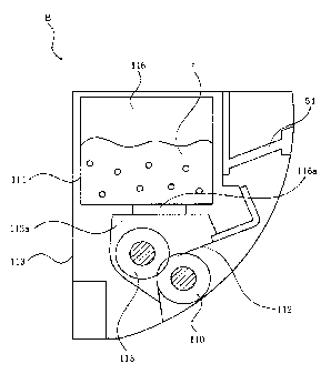
25 In Figure 1 - Figure 3, the cartridge B has a
developing roller 110. The developing roller 110
receives the rotational force through the coupling
CA 02883731 2015-03-03
26
mechanism as will be described hereinafter from the
main assembly A at the time of a developing action to
rotate.
A developer t of a predetermined color is
accommodated in a developer containing frame 114. More
particularly, the frame 114 is provided with a
developer accommodating portion 116 which accommodates
a developer t. The developer t is supplied to the
surface of the developing roller 110 by the rotation
of the developer supply roller 115 in the form of a
sponge in a developer chamber 113a. And, by the
friction between the thin-plate-like developing blade
112, and the developing roller 110, the developer t is
triboelectrically charged, and is formed into a thin
layer. The developer t of the thin layer on a
peripheral surface of the developing roller 110 is fed
to a developing position by the rotation. The
predetermined developing bias is applied to the
developing roller 110. By this, the developing roller
110 develops an electrostatic latent image formed on
the electrophotographic photosensitive drum
(photosensitive drum) 107. In other words the
electrostatic latent image is developed with the
developer t by the developing roller 110. The
developer t used for the development of the
electrostatic latent image by the developing roller
110 is accommodated in the accommodating portion 116.
CA 02883731 2015-03-03
27
The developer t accommodated in the accommodating
portion 116 is supplied to a developer chamber 113a
through a feed opening 116a. An opening 116a is sealed
by a sealing member (unshown) which unsealably seals
the opening 116a. A user pulls out the sealing member
prior to using the cartridge B to unseal the opening
116a. By this, the developer t in the accommodating
portion 116 is supplied to the developer chamber 113a.
The developer which has not contributed to the
development of the electrostatic latent image, that is,
the developer which remains on the surface of the
developing roller 110 is scraped off by a roller 115.
Simultaneously therewith, the new developer is
supplied to the surface of the developing roller 110
by the roller 115. In this manner, the developing
operation is carried out continuously.
The developing cartridge B is in the form of a
developing unit 119. The developing unit 119 includes
a developing device frame 113, and a developer
containing frame 114. The developing unit 119 is
provided with the developing roller 110, the
developing blade 112, the developer supply roller 115,
the developer chamber 113a, and the developer
containing frame 114.
The developing roller 110 is rotatable about a
rotation axis Ll (Figure 5).
The developing cartridge B is mounted to a
CA 02883731 2015-03-03
28
developing cartridge accommodating portion 130a of a
developing rotary member C provided in the main
assembly A by the user (Figure 4). In this case, as
will be described hereinafter, the a drive shaft 180
provided in the main assembly A, and a coupling member
150 of the cartridge B connect with each other in
interrelation with the positioning operation of the
cartridge B to the predetermined position
(photosensitive drum opposing portion) by the
developing rotary member C. And, the developing roller
110 receives the rotational force from the main
assembly A to rotate. The coupling member is a
rotational force transmitting part.
The developing device frame 113 and the
developer containing frame 114 constitute a cartridge
frame.
(2) Electrophotographic image forming apparatus
Referring to Figure 4, a color
electrophotographic image forming apparatus 100 used
with the developing cartridge B will be described.
Here, the color electrophotographic image forming
apparatus 100 is a color laser beam printer as an
exemplary image forming apparatus.
As shown in Figure 4, a plurality of the
cartridges B (131, B2, B3 and B4) which accommodate
different color developers (toner) is mounted on the
rotary member C. The mounting and demounting of the
CA 02883731 2015-03-03
29
cartridge B relative to the rotary member C is carried
out by the user. By the rotation of the rotary member
C by the rotational force from the motor (unshown),
the cartridge B containing the predetermined color
developer opposes to the photosensitive drum 107. The
electrostatic latent image formed on the
photosensitive drum 107 is developed by the developing
roller 110 of the cartridge B. A developed image is
transferred onto the transfer belt 104a. This
development and transfer operation is carried out for
each color. By this, a color image is provided. The
detailed description will be made. A recording
material S is for the formation of an image, and it is
paper, an OHS sheet or the like.
As shown in Figure 4, the light based on the
image information is projected from optical means 101
to the photosensitive drum 107. By this, the
electrostatic latent image is formed on the
photosensitive drum 107. And, the latent image is
developed by the developing roller 110 using the
developer. By this, the developer image is formed on
the photosensitive drum 107. The developer image
formed on the photosensitive drum 107 is transferred
onto the intermediary transfer member.
Then, the developer image transferred onto the
intermediary transfer belt 104a which is a
intermediary transfer member is transferred onto the
CA 02883731 2015-03-03
recording material S by a secondary transfer roller
104b as second transferring means. The recording
material S onto which the developer image has been
transferred is fed to the fixing means 105 which has a
5 pressing roller 105a, and a heating roller 105b. The
developer image transferred onto the recording
material S is fixed on the recording material S. After
the fixing, the recording material S is discharged to
a tray 106.
10 Furthermore, an image formation step will be
described.
The photosensitive drum 107 is rotated counter-
clockwisely (Figure 4) in synchronism with the
rotation of the transfer belt (intermediary transfer
15 member) 104a. The surface of the photosensitive drum
107 is uniformly charged by a charging roller 108.
Thereafter, by the optical means 101, the
photoirradiation of a yellow image is carried out to
the photosensitive drum 107 in response to the image
20 information. By this, an electrostatic latent image
corresponding to the yellow color is formed on the
photosensitive drum 107.
The exposure means has the following structures
The exposure means 101 carries out photoirradiation to
25 the photosensitive drum 107 on the basis of the image
information (image signal including color information)
read from an external device (unshown). By this, the
CA 02883731 2015-03-03
31
electrostatic latent image is formed on the
photosensitive drum 107. The exposure means includes a
laser diode, a polygonal mirror, a scanner motor, an
image formation lens, and a reflection mirror
(unshown).
In more detail, the laser diode emits light in
accordance with the image information, and is directed
by the polygonal mirror as the image light. The
polygonal mirror is rotated at a high speed by the
scanner motor, and the image light reflected by the
polygonal mirror is selectively projected to the
surface of the photosensitive drum 107 by way of the
image formation lens, and the reflection mirror. By
this, the electrostatic latent image corresponding to
the image information is formed on the photosensitive
drum 107.
Simultaneously with a formation of this latent
image, the rotary member C is rotated. By this, a
yellow cartridge Bl is moved to a developing position.
The predetermined bias voltage is applied to the
developing roller 110 of a cartridge Bl. By this, a
yellow developer is deposited to the latent image. By
this, the latent image is developed with the yellow
developer. Thereafter, a bias voltage of the polarity
opposite to the developer is applied to the confining
roller (primary transfer roller) 104j of the transfer
belt 104a. By this, the developer image of the yellow
CA 02883731 2015-03-03
32
color formed on the photosensitive drum 107 is
transferred primarily onto the intermediary transfer
belt 104a.
As has been described hereinbefore, when the
primary transfer of the yellow developer image
finishes, the rotary member C rotates again. A next
cartridge B-2 is moved, and it is positioned to the
position which opposes to the photosensitive drum 107.
These steps are carried out for a magenta cartridge B-
2, a cyan cartridge B3, and a black cartridge B4. By
this, the four-color developer image is overlaid on
the transfer belt 104a.
The yellow cartridge Bl accommodates the
developer of the yellow color, and forms a yellow
developer image. The magenta cartridge B-2
accommodates the developer of a magenta color, and
forms a magenta developer image. The cyan cartridge B3
accommodates the developer of a cyan color, and forms
a cyan developer image. The black cartridge B4
accommodates the developer of a black color, and forms
a black developer image. The cartridges B differ in
the color of the accommodated developer, but they have
the same structures.
During this period, the secondary transfer
roller 104b is not in contact with the transfer belt
104a. At this time. a cleaning charging roller 104f is
not in contact with the transfer belt 104a, either.
CA 02883731 2015-03-03
33
And, after the four color developer image is
formed on the transfer belt 104a, the transfer roller
104b is press-contacted to the transfer belt 104a
(Figure 4). Furthermore, in synchronism with a press-
contact of the transfer roller 104b, the recording
material S which has waited adjacent to a registration
roller couple 103e is fed to a nip between the
transfer belt 104a, and the transfer roller 104b.
Simultaneously, the next recording material S is fed
from the cassette 103a by a feeding roller 103b, and
the feeding roller pair 103c as the feeding means 103.
Here, a sensor 99 is provided immediately
before a registration roller couple 103e. The sensor
99 detects a free end of the recording material S, and
in response thereto, the rotation of the registration
roller couple 103e is stopped, to make the recording
material S wait at the predetermined position.
In addition, the bias voltage of the polarity
opposite to the developer is applied to the transfer
roller 104b. By this, the developer images on the
transfer belt 104a are transferred secondarily onto
the recording material S all together.
The recording material S onto which the
developer image has been transferred is fed to the
fixing means 105 by way of the transportation belt
unit 103f. By this, the developer image is fixed on
the recording material S. And, the recording material
CA 02883731 2015-03-03
34
S having been subjected to the fixing is discharged to
the discharging tray 106 of the upper portion of the
main assembly by the discharging roller pair 103g. By
this, the formation of the image on the recording
material S is completed.
On the other hand, after the end of the
secondary transfer, a charging roller 104f is press-
contacted to the transfer belt 104a. By this, the
predetermined bias voltage is applied to the developer
which remained on the surface of a belt 104a. And, the
residual charge is removed.
The discharged residual developer is
electrostatically re-transferred onto the
photosensitive drum 107 from the belt 104a through the
primary transfer nip. By this, the cleaning of the
surface of the belt 104a is carried out. The residual
developer after the secondary transfer re-transferred
onto the photosensitive drum 107 is removed by a
cleaning blade 117a which is in contact with the
photosensitive drum 107.
The removed developer is collected into a
removed developer box 107d along the feeding path
(unshown).
An accommodating portion 130a is a chamber
which accommodates the cartridge B, and a plurality of
such accommodating portions are provided. In the state
that the cartridge B is mounted to this chamber, the
CA 02883731 2015-03-03
rotary member C unidirectionally rotates. By this, the
coupling member, which will be described hereinafter,
of the cartridge B engages and disengages relative to
the drive shaft 180 provided in the main assembly A.
5 Cartridge B (developing roller 110) is mounted to the
accommodating portion 130a, and therefore, in response
to the movement in one direction of the rotary member
C, it moves in the direction substantially
perpendicular to a direction of the rotation axis L3
10 of the drive shaft 180.
(3) Structure of developing roller
Then, referring to Figure 5, the structure of
the developing roller will be described. In Figure 5,
(a) is a perspective view of the developing roller 110,
15 as seen from main assembly A (driving side). In Figure
5, (b) is a perspective view, as seen from the non-
driving side.
The developing roller 110 includes a shaft
portion 110b, and a rubber portion (elastic material)
20 110a.
The shaft portion 110b is made of
electroconductive material such as iron, and has an
elongated configuration, and is covered by a rubber
portion 110a. The opposite ends 110b1, 110b2 of the
25 shaft portion 110b are supported rotatably through a
bearing (unshown) by the developing device frame 113.
The developing roller 110 is mounted rotatably to the
CA 02883731 2015-03-03
36
developing device frame 113.
The rubber portion 110a coats the shaft portion
110b coaxially The rubber portion 110a carries the
developer t, and develops the electrostatic latent
image by a bias voltage applied to the shaft portion
110b.
A nip width regulation member 136, 137
maintains a uniform width of a nip between the
photosensitive drum 107, and the rubber portion 110a
in the state that the developing roller 110 contacts
to the photosensitive drum 107.
The bearing (unshown) is disposed on each end
110b1, 110b2 of the developing roller 110, to support
the developing roller 110 rotatably.
A regulation member 136 is provided at a one
end of the developing roller 110, and a regulation
member 137 is provided at the other end of the
developing roller 110.
In the state of contacting with the
photosensitive drum 107 the developing roller 110 of
the present embodiment develops the latent image (so-
called contact type developing system).
(4) Drive transmission mechanism (rotational-driving-
force-transmitting mechanism)
A development gear 145 is provided at the end
of the developing roller 110, and a supplying roller
gear 146 is provided at the end of a supplying roller
CA 02883731 2015-03-03
37
115 (Figure 1). And, the gears 145, 146 are fixed to
the shaft. By this, the rotational force which the
coupling member (coupling) 150 receives from the main
assembly A is transmitted to the developing roller 110
through the gear 145, and is transmitted to the
supplying roller 115 through a gear 146. The
rotational force received by the coupling 150 from the
main assembly A may be transmitted to a rotatable
member other than the developing roller 110 and the
supplying roller 115.
The main assembly A is the portion of the
electrophotographic image forming apparatus 100 other
than the cartridge B.
Then, a driving input gear (rotatable member)
147 which supports the coupling 150 will be described.
As shown in Figure 6, a gear 147 is mounted to
the developing unit 119 rotatably at the position for
meshing engagement with the development gear 145 and
the supplying roller gear 146. The gear 147 includes a
development gear portion (first gear portion) 147a and
a supplying roller gear portion (second gear portion)
147b. A gear portion 147a engages with the development
gear 145 to transmit the rotational force received
from the main assembly A to the developing roller 110.
A gear portion 147b engages with the supplying roller
gear 146 to transmit the rotational force received
from the main assembly A to the supplying roller 115.
CA 02883731 2015-03-03
38
The gear 145 is mounted to the end of the developing
roller 110. The gear 146 is mounted to the end of the
supplying roller 115. The gear 147 is provided with a
coupling mounting portion (coupling accommodating
portion) 147j (Figures 8A-8F) therein. A mounting
portion 147j accommodates a driving portion 150b of
the coupling 150. The coupling 150 is restricted in
the movement in the direction of the arrow X34
relative to the gear 147 by the retaining portion 147k
(147k1, 147k2, 147k3, 147k4) provided inside of the
gear 147. The coupling 150 is inclinable relative to
the mounting portion 147j and relative to a rotation
axis L4 of the gear 147 (Figures 16A and 16B). More
particularly, the coupling 150 is inclinable relative
to the axis L4 in the state of being restricted in the
movement toward the driven portion 150a of the driving
portion 150b relative to the mounting portion 147j by
the retaining portion 147k.
The axis L4 is parallel to the rotation axis Li
of the developing roller 110.
The cartridge B has the developing device frame
113 and a supporting member 157, and the supporting
member 157 is mounted to the developing device frame
113 (Figure 2).
The supporting member 157 is provided with a
hole 157j, and the inner surface 157m thereof is in
engagement with the gear 147 (Figures 16C, 16D and
CA 02883731 2015-03-03
39
16E).
(5) Rotational force transmitting part (Coupling, and
coupling member)
Referring to Figure 7A-7F, the description will
be made as to an example of a coupling (coupling
member) as a rotational force transmitting part
according to an embodiment of the present invention.
In Figure 7A is a perspective view of the coupling, as
seen from a main assembly side, and Figure 7B is a
perspective view of the coupling, as seen from a
developing roller side. In Figure 7C shows a view of
the coupling, as seen in the direction perpendicular
to a direction of the rotation axis L2. In Figure 7D,
is a side view of the coupling, as seen from the main
assembly side, and Figure 7E shows a view, as seen
from the developing roller side. In Figure 7E is a
sectional view taken along S3 in Figure 7D. Figure 31
is a perspective view which illustrates only the
coupling illustrated in Figures 13A-13G.
The cartridge B is dismountably mounted to a
cartridge accommodating portion 130a of the rotary
member C provided in the main assembly A. This is
carried out by the user. In the state that the
cartridge B is mounted to the accommodating portion
130a, the rotary member C is rotated by the rotational
force of the motor (unshown). When the cartridge B
reaches a predetermined position (the position which
CA 02883731 2015-03-03
opposes to the photosensitive drum 107, that is, the
developing position), the rotation of the rotary
member C is stopped. By this, the coupling (coupling
member) 150 is engaged with the drive shaft 180
5 provided in the main assembly A. By unidirectionally
rotating the,rotary member C further, the cartridge B
is moved from the predetermined position (developing
position). In other words, it is retracted from the
predetermined position. By this, the coupling 150 is
10 disengaged from the drive shaft 180. It receives the
rotational force from the motor (unshown) provided in
the main assembly A in the state that the coupling 150
is in engagement with the drive shaft 180. The
rotational force is transmitted to the developing
15 roller 110. By this, the developing roller 110 is
rotated by the rotational force received from the main
assembly A.
In this embodiment, the coupling 150 receives
an external force for rotating the developing roller
20 110. The coupling 150 rotates the developing roller
110 by transmitting the external force to the
developing roller 110. Here, according to this
embodiment, the external force is the rotational force
transmitted to the coupling 150 by the drive shaft 180.
25 Thus, the coupling 150 receives the external force
transmitted from the drive shaft 180 to the coupling
150 to rotate.
CA 02883731 2015-03-03
41
In the state that the cartridge B is mounted to
the accommodating portion 130a, it is moved in the
direction substantially perpendicular to the direction
of the rotation axis L3 of the drive shaft 180 in
accordance with the rotation of the rotary member C.
In response to the rotation in one direction of the
rotary member C, the coupling 150 engages with the
drive shaft 180, and is disengaged from the drive
shaft 180.
As has been described hereinbefore, the drive
shaft 180 is provided with a pin 182 (rotational force
applying portion), and is rotated by the motor
(unshown).
The material of the coupling 150 is desirably a
resin material, and is the polyacetal, for example.
This is because the balance in the rigidity, the
toughness, and the processability thereof is suitable
for the present embodiment. However, in order to raise
the rigidity of the coupling 150, in consideration of
a load torque, the rigidity may be raised by adding
the glass fibers in the resin material. In addition, a
metallic material may be used. The material can be
properly selected by the person skilled in the art.
Since the resin material is easy in the processing,
the couplings in the present embodiment are made of
the resin material.
The coupling 150 mainly has the three portions.
CA 02883731 2015-03-03
42
The first portion is a driven portion 150a. As shown
in Figure 7C, the driven portion 150a is engaged with
the drive shaft 180 (as will be described hereinafter).
The driven portion 150a engages with a rotational
force transmitting pin 182 as the rotational force
applying portion (main assembly side rotational force
transmitting part) provided on the drive shaft 180 to
receive the rotational force from the pin 182. The
second portion is a driving portion 150b. In the
driving portion 150b, a pin (rotational force
transmitting part) 155 engages with the driving input
gear (rotational force receiving portion, and
rotational force transmitted portion) 147, and
transmits the rotational force to the gear 147. More
specifically, the driving portion 150b transmits the
rotational force to a mounting portion 147j. The third
portion is the intermediate portion 150c connected
between the driven portion 150a, and the driving
portion 150b.
The pin 182 projects in the each of the two
positions opposed to each other in the direction
perpendicular to a rotation axis L3 of the drive shaft
180 (182a1, 182a2).
As shown in Figure 7F, the driven portion 150a
has a drive shaft insertion opening 150m which expands
from a rotation axis L2 of the coupling 150. The
driving portion 150b has a spherical portion 150i, a
CA 02883731 2015-03-03
43
drive transmission pin 155, and a portion-to-be-
regulated-of-the-coupling 150j. Here, the regulating
portion 150j is substantially co-axial with an axis L2,
and engages with a regulating portion accommodating
portion 160b as will be described hereinafter (Figures
12A-12D). By this, the regulating portion 150j can
regulate an inclining direction of the axis L2. The
detail thereof will be described hereinafter.
An opening 150m is provided with a driving
shaft receiving surface 150f which has the
configuration of a circular cone expanded toward the
drive shaft (180) side. As shown in Figure 7F, a
receiving surface 150f constitutes a recess 150z. The
recess 150z is provided with an opening 150m (opening)
in an opposite side from a driving input gear 147 with
respect to a direction of the axis L2.
By this, the coupling 150 can move relative to
the rotation axis L3 of the drive shaft 180 (pivoting)
without being prevented by a free end portion 180b of
the drive shaft 180, irrespective of a rotational
phase of the developing roller 110 in the cartridge B.
More particularly, the coupling 150 can be moved
(pivoted) between the rotational force transmitting
angular position (the position shown in (d) of Figure
24), and the disengaging angular position (the
position shown in (c) and (d) of Figure 27), and
between the pre-engagement angular position (the
CA 02883731 2015-03-03
44
position shown in (a) of Figure 24), and a rotational
force transmitting angular position (the position
shown in (d) of Figure 24).
The detail thereof will be described
hereinafter.
The two projections (projections) 150d
(engaging portions) are provided at equal intervals
along the phantom circle periphery about the axis L2
in the end surface of the circular recess 150z (150d1
or 150d2). The portions between the projection 150d
constitute the entrance portions 150k (150k1, 150k2).
An interval between the projections 150d1 or 150d2 is
larger than an outer diameter of the pin 182 so that
the intervals can receive the pin 182 provided in the
drive shaft 180. The pin 182 is the rotational force
transmitting part. The spaces between the projection
are the entrance portions 150k1, 150k2. When the
rotational force is transmitted from the drive shaft
180 to the coupling 150, the pins 182 are positioned
in the entrance portions 150k1, 150k2, respectively.
Furthermore, in Figure 7D, a upstream side of the
projections of each 150d with respect to the clockwise
direction is provided with a rotational force
reception surface (rotational force receiving portion)
150e (150e1, 150e2). This rotational force reception
surface 150e is faced against a rotational direction
of the coupling 150. More particularly, the projection
CA 02883731 2015-03-03
150d1 is provided with the receiving surface 150e1,
and the projection 150d2 is provided with the
receiving surface 150e2. In the state that the drive
shaft 180 rotates, the pins 182a1, 182a2 abut to
5 either of the receiving surfaces 150e. By this, the
pins 182a1, 182a2 push the contacted receiving
surfaces 150e. By this, the coupling 150 is rotated
about the axis L2.
More particularly, the coupling 150 receives
10 the external force for rotating the developing roller
110. The coupling 150 rotates the developing roller
110 by transmitting the external force to the
developing roller. Here, according to this embodiment,
the external force is a rotational force transmitted
15 to the coupling 150 by the drive shaft 180. More
particularly, the coupling 150 receives the external
force transmitted to the coupling 150 by the drive
shaft 180 to rotate.
In this embodiment, the projections 150d
20 (rotational force receiving surfaces 150e) are
disposed on the phantom circle periphery about the
axis L2, and they oppose with each other interposing
the center. Therefore, to the coupling 150, the force
is uniformly transmitted from the drive shaft 180. By
25 this, the coupling 150 can stably be rotated with high
degree of accuracy. In this embodiment, only two
projections 150d (rotational force reception surfaces)
CA 02883731 2015-03-03
46
are employed 150e, and therefore, the sizes of the
entrance portions 150k are large. By this, the pin 182
enters easily into the entrance portion 150k.
Therefore, the contact between the rotational force
reception surface 150e, and the pin 182 is assured.
As shown in Figure 7F, the receiving surface
150f has the conical shape, the center thereof is on
the axis L2, and the apex angle thereof is a2. By this,
in the case where the coupling 150 is in the
rotational force transmitting angular position in the
state that the coupling 150 and the drive shaft 180
are in engagement with each other, the free end 180b
of the drive shaft (Figure 24) abuts to the receiving
surface 150f. The axis of the conical shape 1, i.e.,
the axis L2 of the coupling 150, and an axis L3
(Figure 26) of the drive shaft 180 are substantially
co-axial with each other. By this, the coupling 150,
and the drive shaft 180 align with each other, and a
torque transmitted to the coupling 150 is stabilized.
In this embodiment, a2 is 60 degrees - 150 degrees.
Depending on the angle of a2, the non-conical portions
150n of the opening 150m (Figure 7A, and Figure 7D)
may be wide, or it may not be provided (Figure 8B).
It is desirable that the rotational force
reception surface 150e is provided on a phantom circle
(common circle) Cl which has the center 0 on the axis
L2 (Figure 7D). By this, the radius of rotational
CA 02883731 2015-03-03
47
force transmission is constant, and therefore, the
torque transmitted is stabilized. In addition, as for
the projection 150d, the position of the coupling 150
is preferably stabilized by the balance of the forces
received by the coupling 150, by. For this reason, in
the present embodi=nt, the receiving surfaces 150e
are spaced by 180 degrees. In other words, in this
embodiment, the receiving surface 150e1, and the
receiving surface 150e2 diametrically oppose with
respect to the axis L2. By this, the forces which the
coupling 150 receives form a force couple. For this
reason, rotation of the coupling 150 can be continued
only by receiving the force couple. In other words,
the coupling 150 can be rotated without the regulation
of the position of the axis L2.
Here, in the case of the present embodiment, a
diameter of the pin 182 is approx. 2mm. And, a
circumferential length of the entrance portion 150k is
approx. 8mm. Here, the circumferential length of the
entrance portion 150k is the interval between the
adjacent projections 150d on the phantom circle.
However, the present invention is not limited to these
values. In this manner, the pins 182 enter easily the
entrance portions 150k.
In addition, the projection 150d is provided at
a free end portion of the recess 150z. In other words,
it is provided at the free end portion of the coupling
CA 02883731 2015-03-03
48
150. And, the projection (projection) 150d projects in
a crossing direction crossing with the rotational
direction of the coupling 150, and it is provided at
the two places with the intervals along the rotational
direction. By using the two projections 150d, more
assured engagement is possible in engaging with the
rotating drive shaft 180.
Rotary member C (accommodating portion 130a)
rotates in the state that the cartridge B is mounted.
In the state that the developing roller 110 of a
desired developing cartridge B is placed in the
developing position with the rotary member C which is
not rotated, the coupling 150 is engaged with the
drive shaft 180. The receiving surface 150e is in the
state engageable with the pin 182. Or, the receiving
surface 150e engages with the pin 182. The receiving
surface 150e is pushed by the pin 182 for receiving
the force from the rotated drive shaft 180. By this,
the receiving surface 150e receives the rotational
force from the drive shaft 180. In addition, the
receiving surfaces 150e are equidistant from the axis
L2, it is the surfaces of the projections 150d which
diametrically oppose to each other, and face in the
circumferential direction.
An entrance portion (recess) 150k is recessed
in the direction of the axis L2. The entrance portion
150k is formed as the space between the projection
CA 02883731 2015-03-03
49
150d, and the projection 150d. In the case where the
drive shaft 180 is at rest, and when the coupling 150
engages with the drive shaft 180, in the state that
the cartridge B is mounted to the rotary member C, the
pin 182 enters the entrance portion 150k. And, the
receiving surface 150e is pushed by the pin 182 of the
drive shaft 180. Or, when the coupling 150 engages
with the drive shaft 180, in the case where the drive
shaft 180 already rotates, the pin 182 enters the
entrance portion 150k to push the receiving surface
150e. By this, the coupling 150 is rotated. The
rotational force reception surface (rotational force
receiving portion) 150e may be inside of the driving
shaft receiving surface 150f. Or, the receiving
surface 150e may be disposed at the portion which
outwardly projected from the receiving surface 150f in
the direction of the axis L2. In the case where the
receiving surface 150e is disposed inside of the
receiving surface 150f, the entrance portion 150k is
also disposed inside of the receiving surface 150f. In
other words, the entrance portion 150k is the recess,
and is disposed inside of the arc portion of the
receiving surface 150f, and between the projections
150d. In the case nere the receiving surface 150e is
disposed at the portion which outwardly projects, the
entrance portion 150k is the recess, and is disposed
between the projections 150d. Here, the recess may be
CA 02883731 2015-03-03
the hole penetrated in the direction of the axis L2 or
may have the bottom portion. It is satisfactory if the
recess is a space region which is between the
projections 150d. And, it will be satisfactory if the
5 pin 182 can be entered into the region in the state
that the cartridge B is mounted to the rotary member C.
The free end of the driving portion 150b is a
spherical surface, so that irrespective of the
rotational phase in the cartridge B of the gear 147,
10 it can move between the rotational force transmitting
angular position and the pre-engagement angular
position (or the disengaging angular position)
relative to an axis Ll (Figure 10) of the gear 147.
Here, the rotational force transmitting angular
15 position is a first angular position. The pre-
engagement angular position is a second angular
position. The disengaging angular position is a third
angular position. In the illustrated example, the
driving portion 150b is provided with a spherical
20 retaining portion 150i which has the axis L2 as its
axis. A fixing hole 150g co-axial with the centerline
of the driving portion 150b is provided, and the
fixing hole is penetrated by the transmission pin 155.
Furthermore, the driving portion 150b is provided with
25 a cylindrical regulating portion 150j co-axial with
the axis L2 at the position which opposes to the
intermediate portion 150c. The regulating portion 150j
CA 02883731 2015-03-03
51
is engaged with the regulating portion accommodating
portion 160b as will be described hereinafter (Figures
12A-12D). By this, the inclining direction of the axis
L2 of the coupling is regulated. The detail thereof
will be described hereinafter.
The coupling 150 has an integral structure in
this embodiment however separate driven portion 150a,
intermediate portion 150c, and driving portion 150b
may be connected. Other various structures are usable,
but it is satisfactory if the integral operation is
possible as the coupling.
In addition, the coupling 150 is provided with
a circular flat portion 150x and a circular recess
150z at the center 0 of the flat portion 150x at the
free end portion. A rotational force receiving portion
150e projects from the edge of the flat portion 150x,
and they oppose to each other interposing the center
of the flat portion 150x (Figure 6 and so on). In
other words, the free end portion which is provided
with the rotational force reception surface
(rotational force receiving portion) 150e is provided
with the circular flat portion 150x, and the circular
recess 150z provided at the center of the flat portion
150x.
Here, the flat portion 150x may not be employed.
However, in the case where the rotation axis of the
rotary member C swings as shown in the present
CA 02883731 2015-03-03
52
embodiment, it is preferable to provide the flat
portion 150x because when the coupling 150 is engaged
with the drive shaft 180, the engagement is still more
assured.
As has been described hereinbefore, the
coupling 150 as the rotational force transmitting part
is used for the developing cartridge B. The cartridge
B is mounted, and dismounted with the movement in the
direction substantially perpendicular to a direction
of the axis L3 of the drive shaft 180 relative to the
main assembly A of the electrophotographic image
forming apparatus. In other words, the cartridge B is
moved in the direction substantially perpendicular to
the direction of the axis L3 of the drive shaft 180.
The drive shaft 180 is provided in the main assembly A.
The cartridge B is provided with a regulation member
160 which includes a permitting portion 160b2, and a
regulating or confining portion 160b1. The permitting
portion 160b2 permits the revolution of the coupling
150 substantially. The regulating portion 160b1
restricts an inclination angle position of the
coupling 150. In the state that the regulating portion
150j as the projection is positioned in the permitting
portion 160b2, the regulating portion 150j is not
engaged or contacted relative to the regulation member
160.
The coupling 150 has a spherical portion
CA 02883731 2015-03-03
53
(retaining portion) 150i, and the recess 150z at the
one-end portion of the spherical portion 150i with
respect to the longitudinal direction of the coupling
150. The recess 150z is provided at the one-end
portion in the longitudinal direction. The spherical
portion 150i is provided at the other end portion
opposite from the one-end portion. The recess 150z is
engaged with the drive shaft 180 in the state that the
cartridge B is mounted to the main assembly A. The
coupling 150 has the projection 150d. The projections
150d oppose to each other interposing center of the
recess 150z 0 (rotation axis), and they project in the
direction away from the spherical portion 150i in the
longitudinal direction Ll. In other words, the
projections project in the longitudinal direction at
the free end of one-end portion in the longitudinal
direction 150d. The projections 150d receive the
rotational force from the drive shaft 180 in the state
that the cartridge B is mounted to the main assembly A.
The projection 150d is provided in each of the
positions. The coupling 150 has the regulating portion
150j as the projection which projects at the other end
portion of the spherical portion 1501 in the
longitudinal direction. The regulating portion 150j is
movable between the permitting portion 160b2 for
permitting the substantial revolution of the coupling
150, and the regulating portion 160b1 for regulating
CA 02883731 2015-03-03
54
the inclination angle position of the coupling 150 in
the state that the coupling 150 is mounted to the
cartridge B.
The coupling 150 includes the a plurality of
pins (rotational force transmitting part, and
projection) 155 which outwardly project from the
spherical portion 150i interposing the spherical
portion 150i between the projection 150d, and the
regulating portion 150j with respect to the
longitudinal direction of the coupling 150. A pin 155
transmits the rotational force received by the
projection 150d fro. the drive shaft 180 to the
developing roller 110 in the state that the cartridge
B is mounted to the main assembly A. In other words,
the pin 155 is engaged_ with the rotational force
reception surface (rotational force transmitted
portion) 147h to transmit the rotational force to a
receiving surface 147h. By this, the gear 147 rotates,
to transmit the rotational force to the developing
roller 110 through the first gear portion 147a of the
gear 147. In addition, the rotational force is
transmitted to the supplying roller 115 through the
second gear portion 147b of the gear 147.
Here, the longitudinal direction of the
coupling 150 is directed by the free end of the
projection 150d from the free end of the regulating
portion 150j.
CA 02883731 2015-03-03
Furthermore, the coupling 150 includes the
circular flat portion 150x at the free end portion
which is provided with the projection 150d. The recess
150z is provided at the center 0 of the flat portion
5 150x. The projection 150d projects from the edge of
the flat portion 150x, and it opposes relative to each
other interposing the center 0 of the flat portion
150x.
Here, the projection 150d is disposed on the
10 phantom circle 01 about the center 0. In addition, the
regulating portion 150j has a cylindrical shape.
Referring to Figures 8A-8F, a development input
gear 147 which supports the coupling 150 will be
described.
15 An opening 147g 1 or 147g2 shown in Figure 8A
are the groove extended in a rotational axis direction
of the driving input gear 147. In mounting the
coupling 150 a rotational force transmitting pin
(rotational force transmitting part, and projection)
20 155 enters the openings 147g1 or 147g2.
The transmission pin 155 moves in the opening
147g 1 or 147g2. By this, the coupling 150 is movable
between the rotational force transmitting angular
position, and the pre-engagement angular position (or
25 disengaging angular position) irrespective of the
rotational phase of the driving input gear 147 in the
cartridge B.
CA 02883731 2015-03-03
56
In Figure 8A, and 8D, the clockwisely upstream
side of the opening 147 (147g1 or 147g2) is provided
with the rotational force reception surface
(rotational force transmitted portion) 147h (147h1 or
147h2). A side of the transmission pin (rotational
force transmitting part) 155 of the coupling 150
contacts to the receiving surface 147h. By this, the
rotational force is transmitted to the developing
roller 110. In other words, the transmitting surfaces
147h 1 - 147h2 are the surfaces crossed to the
rotational direction of the driving input gear 147. By
this, the transmitting surface 147h (147h1 or 147h2)
is pushed by the side of the transmission pin 155 to
rotate about rotation axis Ll (Figure 8B). Here, the
axis L4 is the rotation axis of the gear 147.
As will be described hereinafter, the coupling
150 is provided with a gap between the pin (rotational
force transmitting part) 155, and the rotational force
reception surface (rotational force transmitted
portion) 147h engaged with it (Figure 8D) so that it
can incline in the substantially all directions
relative to the axis L4.
In this manner, the coupling 150 is mounted to
the longitudinal end portion of the cartridge B.
Therefore, the coupling 150 is inclinable in the
substantially all directions relative to the rotation
axis L4. As has been described hereinbefore, in the
CA 02883731 2015-03-03
57
state that the cartridge B is mounted to a rotary
member C the coupling 150 receives the rotational
force from the drive shaft 180, and transmits the
rotational force to the developing roller 110 (and
supplying roller 115). The coupling 150 has the
rotational force reception surface 150e for receiving
the rotational force from the drive shaft 180 by
engaging with the pin 182, and the pin (projection)
155 for transmitting the rotational force received
through the receiving surface 150e to the developing
roller 110. The pin 182 is the rotational force
applying portion. The rotational force reception
surface 150e is the rotational force receiving portion.
The pin 155 is the rotational force transmitting part.
The pin 155 is engaged with the rotational force
reception surface (rotational force transmitted
portion) 147h to transmit the rotational force to the
receiving surface 147h. By this, the gear 147 rotates,
to transmit the rotational force to the developing
roller 110 through the first gear portion 147a of the
gear 147. The rotational force is transmitted to the
supplying roller 115 through the second gear portion
147b of the gear 147.
When the rotary member C rotates, the coupling
150 contacts to the drive shaft 180 in accordance with
the movement of the cartridge B. By this, the coupling
150 moves from the pre-engagement angular position to
CA 02883731 2015-03-03
58
the rotational force transmitting angular position
with the movement of the coupling 150 to the
permitting portion 160b2 from the regulating portion
160b1. By this, the coupling 150 opposes to the drive
shaft 180 to receive the rotational force from the
drive shaft 180. And, when the rotary member C further
rotates from the position in which the coupling 150
opposes to the drive shaft 180, the coupling 150 moves
from the rotational force transmitting angular
position to the disengaging angular position in
accordance with the movement of the cartridge B. By
this, the coupling 150 disengages from the drive shaft
180.
As shown in Figure 8B), the gear 147 is
provided with a cou-)ling mounting portion 147j which
accommodates the drive transmitting portion 150b of
the coupling 150.
The mounting portion 147j is provided with the
retaining portion (spherical portion) 147k (147k1-
147k4) for preventing the disengagement, from the gear
147, of the accommodated transmitting portion 150b.
Figure 8B is a sectional view illustrating the
step of fixing the coupling 150 to the gear 147.
First, the coupling 150 is moved in an X33
direction. Then, the transmitting portion 150b is
inserted into the mounting portion 147j. Before the
insertion, the diameter pZ6 of retaining portion
CA 02883731 2015-03-03
59
(spherical portion) 150i is larger than diameter D15
(Figure 8A) of the circle constituted by the inside
edge lines 147m (147m1-147m4) of the retaining portion
147k. In other words, a relation of Z6 > D15 is
satisfied.
In accordance with the insertion of the
transmitting portion 150b, retaining portion 147k
(147k1-147k4) is temporarily retracted radially
outwardly of the gear 147 by the elastic deformation
thereof. By this, the transmitting portion 150b can be
inserted into the mounting portion 147j. In other
words temporarily, the relation of D15 > Z6 is
satisfied. When the insertion of the transmitting
portion 150b to the mounting portion 147j is completed,
the retaining portion 147k (147k1-147k4) elastically
deformed is restored. In other words the relation of
Z6 > D15 is satisfied.
Then, the retaining member 156 is inserted in
the direction of the arrow X33, and is fixed to the
gear 147. Here, the outer diameter D10 of the driven
portion 150a is smaller than the diameter D16 of an
opening 156i of the retaining member 156. In other
words the relation of D16 > D10 is satisfied. By
satisfying this relation, in the state that the
coupling 150 is inserted into the gear 147, the
retaining member 156 can be inserted into the gear 147.
As shown in Figure 8C), by the insertion of the
CA 02883731 2015-03-03
retaining member, the elastical deformation of
retaining portion 147k (147k1-147k4) radially outward
of the gear 147 is prevented. By this, the relation of
Z6 > D15 is maintained. In this state, even in the
5 case where the force in the direction opposite from
the inserting direction is applied to the coupling 150,
the disengagement of the coupling 150 from the gear
147 can be prevented. In addition, the force in the
direction opposite an inserting direction is the force
10 in X34 direction when the coupling 150 (transmitting
portion 150b) disengages from the mounting portion
147j. This is because, the transmitting portion 150b
is contacted to the retention surface 1471 (14711-
14714 (14713 and 14714 are unshown), Figure 8B)) of
15 the retaining portion 147k (147k1-147k4), and the
further movement is restricted. The mounting portion
147j is provided inside of the gear 147.
By this, the coupling 150, the gear 147 and the
retaining member 156 are unified to provide a drive
20 unit U (Figure 80, 8A and Figure 16B)).
As shown in Figure 8E, the retaining member 156
as will be described hereinafter which functions as a
coupling retaining portion 157a of the supporting
member 157 can be unified with the supporting member
25 157. In this case, the step of fixing the retaining
member 156 to the gear 147 in the step described above
is omitted. In mounting the coupling 150 as will be
CA 02883731 2015-03-03
61
described hereinafter to a developing device frame
(cartridge frame) 113, the coupling retaining portion
157a of the supporting member 157 is inserted into the
gear 147 (Figure 8F). In the state shown in Figure 8F,
the retaining portion 157a prevents the radially
outward elastical deformation of the retaining portion
147k (147k1-147k4) of the gear 147. By this, the
retaining portion 157a prevents the disengagement of
the coupling 150 from the gear 147. A function of the
retaining portion 157a described above is the same as
the function of the retaining member 156.
The coupling 150 is movable (pivotable) between
the rotational force transmitting angular position,
and the disengaging angular position, and between the
rotational force transmitting angular position, and
the pre-engagement angular position in the gear 147.
Retaining portion 147k (147k1-147k4) restricts the
movement of the coupling 150 in the direction of X34
relative to the gear 147. In other words, the inside
edge line 147m (147m1-147m4) of an opening has a
diameter cp15 smaller than a diameter Z6 of the
retaining portion 150i.
As has been described hereinbefore, a bearing
portion 160a engages rotatably with the gear 147
(rotatable member) which has the development gear
portion (first gear portion) 147a, and the supplying
roller gear portion (second gear portion) 147b. The
CA 02883731 2015-03-03
62
coupling 150 is mounted to the inside of the gear 147.
The coupling 150 is mounted. By such a structure, a
coupling mounting structure is a compact. Similarly to
the projection 150d, it is desirable that a rotational
force transmitting surface (rotational force
transmitting part) 150h 1 or 150h2 diametrically
opposes on the same circumference.
By the unification as described above, the
coupling 150, and the gear 147 can be treated as a
unit. By this, a handling at the time of assembling
the coupling 150 to the cartridge B is easy. Therefore,
the improvement of the assembling property can be
accomplished. If strength of the retaining portion
147k is sufficient, the retaining member may be
omitted.
As has been described hereinbefore, the
coupling 150 is mounted to the gear 147, so that a
rear end portion thereof is revolvable inside of the
gear (rotatable member) 147, and the coupling 150 does
not disengage from the gear 147. In other words the
coupling 150 has the retaining portion (spherical
portion) 150i so that the movement toward the free end
portion in the longitudinal direction (direction of
the axis L2) of the coupling 150 is regulated. The pin
(rotational force transmitting part) 155 projects in
the direction perpendicular to the longitudinal
direction from the retaining portion 150i. The
CA 02883731 2015-03-03
63
movement of the retaining portion 150i toward the free
end portion is regulated by the retaining portion 147k.
By such the structuie, the coupling mounting structure
is compact.
The free end portion of the coupling 150 is the
side which opposes to the drive shaft 180 (side
engaged with the drive shaft 180) in the state that
the cartridge B is mounted to the rotary member C. The
rear end portion is the side opposite from the free
lo end portion, and is the side at which the rotational
force is transmitted to the developing roller 110
(side mounted to the gear 147).
Referring to Figures 10A1-10A5 and 10B1-10B5,
the description will be made as to a range of the
movement of the coupling 150 relative to the gear 147.
Figure 10 is a view showing a connection state
between the gear 147 and the coupling 150. (al) - (a5)
of Figure 10 is a view, as seen in the direction of
the drive shaft 180, and (bl) - (b5) of Figure 10 is a
perspective view thereof.
As shown in Figure 10, the coupling 150 is
mounted so that the rotation axis L2 thereof can
incline in all directions relative to the axis L4. The
drive shaft 180 is provided in the main assembly A at
the one longitudinal end portion of the rotary member
C. The drive shaft 180 is provided at the
predetermined position in the main assembly A so that
CA 02883731 2015-03-03
64
it is rotatable. The drive shaft 180 is fixed to the
main assembly A so that it does not move in the
direction substantially perpendicular to the rotation
axis thereof. In other words a rotation axis of the
drive shaft 180 per se does not shift in the direction
substantially perpendicular to the rotation axis
thereof. The drive shaft 180 is not mounted to a
member which swings in the direction substantially
perpendicular to the rotation axis thereof with the
rotary member C. The axis L2 is co-axial with the axis
L4 in (al), and (bl) of Figure 10. Figures 10A2 and
10B2 show the state when the coupling 150 inclines
upward from this state. The coupling 150 inclines
toward an opening 147g. In this state, the
transmission pin 155 is moved along the opening 147g
((Figure 10A2 and B2). As a result, the coupling 150
inclines about an axis AX perpendicular to the opening
147g.
In Figures 10A3 and 10B3, the coupling 150
inclines rightward. When the coupling 150 this
inclines in the orthogonal direction perpendicular to
the opening 147g, the pin 155 is rotated in the
opening 147g. The axis of the pin 155 at the time of
the pin 155 rotating is the central axis AY of the pin
155.
In Figures 10A4 and 10E4, and Figure 10A5 and
10B5, the state that the coupling 150 is inclined
CA 02883731 2015-03-03
downward, and the state of being inclined leftward are
shown. The coupling 150 inclines about the rotation
axes AX and AY.
Here, the inclination of the coupling 150 is a
5 combined inclination of the rotation around the axis
AX, and the rotation around the axis AY. In addition,
this direction is the direction shown in Figures 10A2
and 10A3; 10A3 and 10A4; 10A4 and 10A5; and 10A5 and
10A2. In this manner, the axis L2 can incline in all
10 directions relative to the axis Ll.
It has been described that the axis L2 is
inclinable in all directions relative to the axis L4.
However, it is not necessary that the axis L2 is
inclinable to the predetermined angle in any direction
15 over 360 degrees to the axis L4. For example, the
opening 147g is made relatively wide in the
circumferential direction, for example. With such a
setting, when the axis L2 inclines relative to the
axis L4, the coupling 150 rotates slightly about the
20 axis L2 even in the case where the coupling cannot
incline up to the predetermined angle linearly. By
this, the axis L2 can incline to the predetermined
angle relative to the axis L4. In other words a play
in the rotational direction of the opening 147g can be
25 selected properly, as needed.
As has been described hereinbefore referring to
Figure 8A-8F, a spherical surface 150i contacts to the
CA 02883731 2015-03-03
66
retention surface 1471. For this reason, the coupling
150 is mounted rotatably about the center P2 of the
spherical surface 150i. In other words, the axis L2 is
inclinable irrespective of a phase of the gear 147. In
further words the coupling 150 is revolvable relative
to the axis L4. As will be described hereinafter, in
order to engage the coupling 150 with the drive shaft
180, it is necessary that the axis L2 inclines toward
the downstream side with respect to a rotational
direction X4, relative to the axis L4, immediately
before the engagement. As shown in Figures 11A-11D, in
other words, it is necessary that the axis, 12 of the
coupling 150 inclines relative to the axis L4, so that
the position of the driven portion 150a is the
downstream with respect to the rotational direction X4
of the rotary member C.
Figure 2 illustrates the state that the axis L2
inclines relative to the axis L4. Figure 9 is a
sectional view taken along S24-S24 of Figure 2.
By the structure described in the foregoing,
the coupling can also be shifted to the state that the
axis L2 is substantially parallel with the axis L4
from the state that the axis L2 inclines as shown in
Figure 9. The maximum possible inclination angle a4
(Figure 9) of the axis L4 and the axis L2 is the angle
that a driving portion 150a and intermediate portion
150c contacts to the end member 151, and the
CA 02883731 2015-03-03
67
supporting member 157. The angle a4 may be set to the
angle required when mounting and demounting on the
main assembly.
Here, the maximum possible inclination angle A
is 20 degrees - 80 degrees in the case of the present
embodiment. In the foregoing, it has been described
hereinbefore that it is necessary that the axis L2
inclines downstream in the rotational direction X4
relative to the axis L4 immediately before the
coupling 150 engages with the drive shaft 180. The
regulating or confining method will be described.
(6) Angular position regulating member
Referring to Figures 12A-12D and Figures 13A-
13G, the description will be made as to the angular
position regulation member (regulation member) for
regulating the inclining direction of the coupling
150. .
The rotational force transmitting angular
position is the first angular position. The pre-
engagement angular position is the second angular
position. The disengaging angular position is the
third angular position.
According to the regulation member 160 of the
present embodiment, the coupling 150 can be maintained
in the pre-engagement angular position (second angular
position) even if it is before the cartridge B is
mounted to the rotary member C. The coupling 150 can
CA 02883731 2015-03-03
68
be maintained in the pre-engagement angular position
(second angular position) also in the free state of
the cartridge B. Therefore, when the cartridge B is
transported, for example an unintended movement of the
coupling 150 is prevented.
This is one of the remarkable effects according
to an embodiment of the present invention.
Figure 12A is a perspective view of the
regulating portion 160, as seen from the outside with
respect to the longitudinal direction of the
developing roller 110. Figure 12B is a side view of
the regulating portion 160, as seen from the outside.
Figure 12C and 12D illustrates another embodiment of a
configuration of the regulating portion 160. Figure
13A is a perspective view illustrating the positional
relation between the coupling 150, and the regulation
member 160 in the state that the coupling 150 is in
the rotational force transmitting angular position (as
will be described hereinafter). Figure 13B is a
perspective view illustrating the positional relation
between the coupling 150, and the regulating portion
160 in the state that the coupling 150 is in the pre-
engagement angular position (as will be described
hereinafter). In addition, Figures 13C and 13D
illustrate the states of the gear 147, and the
retaining member 156 in the state of Figure 13A, and
Figure 13B. Figure 13E is a perspective view
CA 02883731 2015-03-03
69
illustrating the state that the portion-to-be-
regulated-of-the-coupling 150j is positioned in a
positioning portion (regulating portion) 160b1. Figure
13F is a perspective view illustrating the state that
the regulating portion 150j is positioned in the
permitting portion 160b2. Figure 13G is a perspective
view of the coupling 150 engaged with the regulation
member 160, as seen from the bottom. In Figure 13G,
the bottom of the regulation member 160 is not
illustrated. Actually, the regulation member 160 is
provided with the bottom, and therefore, the
regulating portion 150j is not visible.
The regulation member 160 is provided with the
circular bearing portion 160a and the regulating
portion accommodating portion 160b. The regulation
member 160 is provided with a groove 160g. An
accommodating portion 160b is a groove. The bearing
portion 160a surrounds the groove 160g. The
accommodating portion 160b includes a positioning
portion 160b1 and permitting portion 160b2. The
regulation member 160 is integral with the bearing 138
described above. Therefore, the regulation member 160
is provided on an outside surface of the bearing 138.
The bearing portion 160a supports inner surface
147i (Figure 8B) of the gear 147 rotatably. The inner
surface 147i engages with an outer surface of the
bearing portion 160a. By this, the gear 147 is mounted
CA 02883731 2015-03-03
rotatably to the bearing portion 160a. The regulating
portion 150j is accommodated in the accommodating
portion 160b. In this state, the coupling 150 freely
is movable within the range that the regulating
5 portion 150j does not interfere with the wall 160b3 of
an accommodating portion. The portion-to-be-regulated
150j has the cylindrical shape. The portion-to-be-
regulated 150j projects away from the intermediate
portion 150c co-axially with the axis L2 from the
10 driving portion 150b. The portion-to-be-regulated 150j
projects from the end of the coupling 150. More
specifically, the portion-to-be-regulated 150j is co-
axial with the retaining portion (spherical portion)
150i, and projects away from the intermediate portion
15 150c from the retaining portion 150i. With such a
structure, the coupling mounting structure is compact.
Before engaging with the drive shaft 180, the coupling
150 takes the pre-engagement angular position by
elastic material (urging member) or the like as will
20 be described hereinafter. At this time, the portion-
to-be-regulated 150j contacts to the positioning
portion (regulating portion) 160b1. More particularly,
the inclining direction of the coupling 150 is
regulated by abutting a part for a circular column
25 portion of the portion-to-be-regulated (projection)
150j to a wall 160b4 of the V-shaped groove portion as
the positioning portion 160b1. The portion-to-be-
CA 02883731 2015-03-03
71
regulated (projection) 150j of the coupling 150
projects at a trailing end at the opposite side from
the end which is provided with the rotational force
reception surface (rotational force receiving portion)
150e. The portion-to-be-regulated 150j is regulated in
the inclining direction by abutting to a narrow
portion 160b7 of the V-shaped groove portion 160b4 as
the positioning portion 160b1. The coupling 150 is
regulated in the inclination angle by the abutment to
the positioning portion 160b1 of the free end of the
regulating portion 150j. Therefore, the coupling 150
is positioned at an optimal pre-engagement angular
position for the engagement with the drive shaft 180.
In this manner, the regulating portion 150j is
regulated in the inclining direction by the
positioning portion 160b1. By this, the coupling 150
is positioned to the pre-engagement angular position
(in Figure 13E, the inclinded coupling 150 is
positioned at the pre-engagement angular position).
This position will be described hereinafter. The
positioning portion 160b1 functions as the positioning
portion only in the case where the coupling 150 is in
the pre-engagement angular position.
In the case where the coupling 150 is in the
position other than the pre-engagement angular
position, it is freely movable within the range in
which the regulating portion 150j does not interfere
CA 02883731 2015-03-03
72
with the wall 160b3 of the permitting portion 160b2.
When in the case where the coupling 150 is in a
position between the pre-engagement angular position,
and the rotational force transmitting angular position,
the rotational force transmitting angular position, a
position between the rotational force transmitting
angular position, and the disengaging angular position,
or the disengaging angular position, in the range that
the regulating portion 150j does not interfere with
the wall 1603 of the permitting portion 160b2, it is
freely movable. In other words, in the case where the
portion-to-be-regulated 150j does not contact to the
positioning portion (regulating portion) 160b1, the
coupling 150 is revolvable (in Figure 13F, and Figure
13E, perpendicular coupling 150). By doing so, by, in
the state that the coupling 150 is in engagement with
the drive shaft 180, when it moves from the pre-
engagement angular position to the rotational force
transmitting angular position, or when it moves from a
rotational force transmission position to the
disengaging angular position, the coupling 150 can be
moved with the drive shaft 180. Therefore, a stress
imparted to the coupling 150 can be suppressed in the
case where the rotary member C as will be described
hereinafter moves radially, more particularly, in the
case where the coupling 150 moves in the radial
direction of the rotary member C. Therefore, the
CA 02883731 2015-03-03
73
coupling 150 can be smoothly engaged with the drive
shaft 180, and can be smoothly disengaged from the
drive shaft 180. The permitting portion 160b2 is
constituted by a wide portion 160b8.
In the case where the coupling 150 moves from
the position other than the pre-engagement angular
position to the pre-engagement angular position by the
urging member, the portion-to-be-regulated 150j is
guided by the wall 160b3 of the permitting portion
160b2, and is guided to the positioning portion 160b1.
The coupling 150 inclines to the pre-engagement
angular position.
As has been described hereinbefore, the
regulation member 160 has the positioning portion
(regulating portion) 160b1 for regulating the coupling
150 at the pre-engagement angular position before
engaging with the drive shaft 180, and the permitting
portion 160b2 for permitting the substantial
revolution of the coupling 150 member.
As for the configuration of the portion-to-be-
regulated accommodating portion 160b, the
configuration as shown in Figure 12C and Figure 12D
can be used, if the positioning portion 162a and the
permitting portion 162b satisfy the functions
described above. In the embodiment shown in 12C, the
configuration of the positioning portion (regulating
portion) 160b1 is an arc shape 160b6, and the
CA 02883731 2015-03-03
74
configuration of the permitting portion 160b2 is a
curved surface. In the embodiment shown in Figure 12D,
the configuration of the permitting portion 160b2 is
curved.
As has been described hereinbefore, the
regulation member 160 is provided with the groove 160g.
The groove 160g includes a narrow portion 160b7 as the
positioning portion 160b1 as the regulating portion,
and a wide portion 160b8 as the permitting portion
160b2. The trailing end of the coupling 150 includes
the portion-to-be-regulated 150j (projection) which is
projected. In the state that the portion-to-be-
regulated 150j is positioned in the narrow portion
160b7, the inclining direction of the coupling 150 is
restricted to the pre-engagement angular position, and
in the state that the portion-to-be-regulated 150j is
positioned in the wide portion 160b8, the inclination
of the coupling 150 to the rotational force
transmitting angular position from the pre-engagement
angular position is permitted. The portion-to-be-
regulated 150j is regulated by contacting to the wall
160b4 of the narrow portion 160b7. In the case where
the portion-to-be-regulated 150j is positioned in the
permitting portion 160b2, the coupling 150 is
revolvable. In other words the coupling 150 can be
revolved relative to the axis L4. In the state that
the coupling 150 is revolvable, the portion-to-be-
CA 02883731 2015-03-03
regulated 150j is in the wide portion 160b8, and does
not contact to the wall 160b3.
The peripheral surface of the groove 160g is
surrounded by the circular bearing portion (circular
5 portion) 160a. The bearing portion 160a engages
rotatably with the gear 147 (rotatable member) which
has the development gear portion (first gear portion)
147a, and the supplying roller gear portion (second
gear portion) 147b. The coupling 150 is mounted to the
10 inside of the gear 147, and in the case where the
coupling 150 (portion-to-be-regulated 150j) is
positioned in the permitting portion 160b2, the
coupling 150 is revLlvable substantially.
As has been described hereinbefore, in the
15 regulation member 160 of the present embodiment, even
if it is before the cartridge B is mounted to the
rotary member C, the coupling 150 can be maintained in
the pre-engagement angular position (second angular
position). In other words even in the case where the
20 cartridge B is in the free state, the coupling 150 can
be maintained in the pre-engagement angular position
(second angular position). Therefore, in transporting
the cartridge B, for example, the inadvertent movement
of the coupling 150 can be prevented.
25 Referring to Figures 14 and 15, the description
will be made as to a coupling elastic material (urging
member) for moving the coupling to the pre-engagement
CA 02883731 2015-03-03
76
angular position. Figure 14 is a perspective view
illustrating the state that the elastic material 159
is mounted to the supporting member 157. Figure 15 is
a perspective view of the cartridge B in the state
that the urging member 159 is mounted to the
supporting member 157.
As shown in Figure 14, a lateral surface 157i
of the supporting member (mounting member) 157 is
provided with a spring mounting portion 157e1 and a
spring rotation-stopper 157e2. A coil part (end) 159b
of a torsion coil spring (urging member and elastic
material) 159 is fixed to the mounting portion 157e1.
A rotation-stopper arm 159c for a spring 159 contacts
to the spring rotation-stopper e2. As shown in Figure
15, a contact portion 159a of the spring 159 contacts
to the intermediate portion 150c of the coupling 150.
In this state, the spring 159 is twisted to produce
the elastic force. By this, the axis L2 of the
coupling 150 inclines relative to the axis L4 (Figure
15). In other words the coupling 150 inclines to the
pre-engagement angular position. The a contact
position of the spring 159 relative to the
intermediate portion 150c is in the upstream side from
the center of the driving portion 150b of the coupling
150 in the rotational direction X4. For this reason,
the axis, 12 inclines relative to the axis L4, so that
the driven portion (150a) side moves toward the
CA 02883731 2015-03-03
77
downstream side with respect to the rotational
direction X4. The rotational direction X4 shows the
rotational direction of the rotary member C.
In this embodiment, although the torsion coil
spring is used as the spring 159, this is not
restrictive in the present invention. For example, it
may be another elastic material (urging member), for
example, leaf spring, rubber, sponge. However, a
certain amount of stroke is required in order to
incline the axis L2. For this reason, it preferably
has a certain stroke. In order to make the coupling
150 be positioned in the pre-engagement angular
position (first angular position), the spring (urging
member and elastic material) 159 urges the coupling
150 by the elastic force thereof so that the coupling
150 is positioned in the regulating portion 160b1. By
urging the coupling by the elastic force of the spring
(urging member, and elastic material), the coupling
150 can be maintained in the pre-engagement angular
position (first angular position) more assuredly. In
other words by the spring (urging member, and elastic
material) 159, the coupling 150 elastically urges to
the positioning portion (regulating portion) 160b1.
When the rotary member C rotates, the coupling
150 contacts to the drive shaft 180 by the movement of
the cartridge B. By this, the coupling 150 moves to
the permitting portion 160b2 from the regulating
CA 02883731 2015-03-03
78
portion 160b1 against the elastic force of the spring
(elastic material) 159. With this movement, the
coupling 150 moves from the pre-engagement angular
position to the rotational force transmitting angular
position. By this, the coupling 150 opposes to the
drive shaft 180 to receive the rotational force from
the drive shaft 180. When the rotary member C further
rotates from the position in which the coupling 150
opposes to the drive shaft 180, the coupling 150 moves
from the rotational force transmitting angular
position to the disengaging angular position against
the elastic force of the spring 159, in accordance
with the movement of the cartridge B. By this, the
coupling 150 disengages from the drive shaft 180.
(7) assembly of coupling to cartridge frame
Referring to Figures 16A-16E, the method of
assembling the coupling 150 to the developing device
frame (cartridge frame) will be described. Figure 16A
is a perspective view of the cartridge B before the
gear 147 including the coupling 150 and the retaining
member 156, the supporting member (rotatable member)
147, and the spring 159 are mounted. Figure 16B is a
perspective view of the cartridge B before mounting a
mounting member 157, and spring 159. Figure 160 is a
perspective view of the cartridge B before mounting
the spring 159. Figure 16D is a perspective view of
the cartridge B after the completion of the mounting.
CA 02883731 2015-03-03
79
Figure 16E is an exploded perspective view of the
cartridge B in the longitudinal direction after the
completion of the mounting with the positional
relation in the direction perpendicular to the
longitudinal direction unchanged.
The bearing 138 provided with the regulation
member 160, the developing roller 110 and the
developer supply roller 115 are mounted to the
developing device frame 113 (cartridge frame). A
developing roller gear 145 for transmitting the
rotational force from the gear 147 to the developing
roller 110 is mounted to the developing roller 110. A
developer supply roller gear 146 for transmitting the
rotational force from the gear 147 to the developer
supply roller 115 is mounted. to the developer supply
roller 115.
The bearing 138 is mounted by a screw 138a to
the one longitudinal end portion of the developing
device frame 113 (Figures 16A and B).
First, drive unit U (the gear 147 which is
provided with the coupling 150 and the retaining
member 156) is mounted to the regulation member 160
(Figures 16A and 16B). At this time, the circular
column portion as the portion-to-be-regulated
(projection) 150j is accommodated by the groove as the
accommodating portion 160b (Figure 13B). The inner
surface 147i engages with a circular outer surface of
CA 02883731 2015-03-03
the bearing portion (circular portion) 160a. By this,
the gear 147 is mounted rotatably to the bearing
portion 160a (Figures 16A and 16B). In this state, the
gear portion 147a of the gear 147 is engaged with the
5 developing roller gear 145 to transmit the rotational
force to the developing roller 110. A supplying roller
gear portion 147b of the gear 147 engages with the
developer supply roller gear 146, to transmit the
rotational force to the roller 115. The coupling 150
10 is freely movable in the range in which the portion-
to-be-regulated 150j does not interfere with the wall
of the accommodating portion 160b in the regulation
member 160. The bearing portion 160a as the circular
portion surrounds the groove 160g (Figures 12A - 12C).
15 Then, the supporting member 157 is mounted to
the developing device frame 113 (Figure 16D). In the
case of the mounting, the coupling 150 passes through
an opening 157j of the supporting member 157, and the
bearing 138, and the supporting member 157 contact to
20 each other. The supporting member 157 has a
positioning portion (unshown) at a position, and a
rotation stopper (unshown) at a position relative to
the developing device frame 113. The supporting member
157 is positioned with respect to the widthwise
25 direction of the developing device frame 113. The gear
147 is supported rotatably by the bearing portion 160a
as a gear supporting portion. The disengagement of the
CA 02883731 2015-03-03
81
retaining member (retention ring) 156 from the gear
147 is prevented by the retaining portion 157k 1571.
The supporting member 157 is mounted to the developing
device frame 113 by screws 157a, 157b. The method for
the mounting of the bearing 138, and the supporting
member 157 to the developing device frame 113 is
properly selected by the person skilled in the art.
Finally, the spring 159 is mounted to a spring
supporting portion 157e1 of the supporting member 157
(Figure 16D). At this time, the intermediate portion
150c of the coupling 150 is contacted to the urging
direction downstream of the contact portion 159a of
the spring 159. In this state, the coupling 150
inclines toward the downstream with respect to the
rotational direction X4 of the rotary member C by the
spring 159. In this state, the portion-to-be-regulated
150j contacts to the positioning portion 160b1. The
positioning portion 160b1 has the shape of V, and the
portion-to-be-regulated 150j is contacted to the V-
shaped groove portion 160b4. In other words the
coupling 150 is positioned at the pre-engagement
angular position.
As for the mounting method described above, the
order of the steps may be changed, for example, after
mounting the gear 147 to the supporting member
(rotatable member) 157, these are mounted to the
developing device frame 113.
CA 02883731 2015-03-03
82
As has been described hereinbefore, the
peripheral surface of the groove 160g is surrounded by
the circular bearing portion (circular portion) 160a.
The bearing portion 160a as the circular portion
engages rotatably with the gear (rotatable member) 147
which is provided with the first gear portion 147a,
and the second gear portion 147b. In the case that the
coupling 150 is mounted to the inside of the gear 147,
and the portion-to-be-regulated 150j is positioned in
lo the permitting portion 160b2 the coupling 150 is
revolvable substantially.
While the portion-to-be-regulated 150j is
positioned in the permitting portion 160b2, in the
coupling 150, a gap is provided between the pin
(rotational force transmitting part) 155, and the
rotational force reception surface (rotational force
transmitted portion) 147h for receiving the rotational
force from the pin 155 so that it is revolvable
substantially. The pin 155 is movable relative to the
receiving surface 147h. In the rotational direction of
the coupling 150, the pin 155, and the receiving
surface 147h contact with each other. The coupling 150
is provided at the end of the cartridge B.
More particularly, mp in the coupling 150, a
gap is provided between the pin (rotational force
transmitting part) 155, and the rotational force
reception surface (rotational force transmitted
CA 02883731 2015-03-03
83
portion) 147h so that it is revolvable substantially
in the state that the portion-to-be-regulated 150j is
positioned in the permitting portion 160b2. The pin
(rotational force transmitting part) 155 is movable
relative to the rotational force reception surface
(rotational force transmitted portion) 147h. In the
rotational direction in which the coupling 150 rotates,
the pin 155, and a rotational force reception surface
147h contact to each other. The pin 155 transmits the
rotational force received from the drive shaft 180 to
the developing roller 110 through the rotational force
reception surface (rotational force receiving portion)
150e. The pin 155 is provided on the coupling 150.
The rotational force reception surface 147h is
provided inside of the gear 147 as the rotatable
member.
(8) Mounting and demounting method of developing
cartridge relative to color electrophotographic image
forming apparatus main assembly
Referring to Figures 17-19, the mounting and
dismounting operation of the cartridge B relative to
the main assembly A will be described.
Figure 17 is a sectional view illustrating a
developing cartridge mounting and demounting waiting
position (waiting position) HP that the rotary member
C is shifted by a predetermined angle phase from a
developing position DP. The rotary member C takes the
CA 02883731 2015-03-03
84
waiting position HP (home position) except during the
developing operation, and the mounting and dismounting
operation of cartridge B (B1-B4) is also carried out
in the position. In this embodiment, only a position
About 45-degrees upstream of the developing position
DP is the waiting position H.
The mounting and demounting operation of the
cartridge B relative to the rotary member C is carried
out by the user in the state that the rotary member C
is rest at the waiting position H.
In the mounting and demounting of cartridge B
(B1-B4) relative to the rotary member C, a cover 13 is
first opened. By this, the user can mount and demount
cartridge B (B1-B4) relative to the rotary member C.
Figure 17 is a sectional view illustrating the state
that a yellow cartridge B1 among the four cartridge s
B is positioned in the waiting position H. The cover
13 is opened. The cover 13 is operated interrelatedly
with an interlocking SW (unshown). More particularly
by releasing the cover 13, the interlocking SW is
rendered into OFF state to stop the drive in the main
assembly A. Designated by 19 is a cartridge releasing
members (Figure 4, Figure 17). The releasing member 19
operates a locking member (unshown) for locking the
cartridge B in the rotary member C. More particularly
the locking member (unshown) engages by the releasing
member 19 with a guide portion (portion-to-be-locked)
CA 02883731 2015-03-03
60b (Figure 19), by which, the cartridge B is locked
by the rotary member C. A guide portion 60b is
provided in the cartridge B. By releasing the cover 13,
the releasing member 19 moves the locking member
5 (unshown) to the position which is not engaged with
the guide portion 60b. By this, only in the cartridge
Bl which is positioned in the waiting position HP, the
engagement with the rotary member C is released.
Therefore, the user can dismount the cartridge B1 from
10 the rotary member C (Figure 17, Figure 18). As has
been described hereinbefore, the cartridge B has the
guide portion 60b for being guided in the direction
perpendicular to the direction of the axis Li of the
developing roller 110 (longitudinal direction of
15 developing roller 110).
As shown in Figure 4, when the user shuts the
cover 13, the projection 13a provided on the cover 13
rotates the releasing member 19 counterclockwisely. By
this, the releasing member 19 engages the locking
20 member (unshown) with the guide portion 60b.
Accordingly, when the cover 13 is shut, the cartridge
B is locked to the rotary member C. When interlocking
SW is in the ON state, all of the cartridges B (B1-B4)
mounted to the rotary member C are locked. For this
25 reason, the trouble that the driving mechanism of the
main assembly A unintentionally starts can be avoided
assuredly with cartridge B (B1-B4) unlocked.
CA 02883731 2015-03-03
86
The mounting of the cartridge B to the main
assembly A will be described.
As shown in Figure 18, when the user grips the
handle 54, an orientation of the cartridge B is
determined in general by a gravity center of the
cartridge. This orientation is near to the orientation
required when the cartridge B passes through the
opening 30 provided in an upper portion of the main
assembly A.
The cartridge, b is provided with an elongated
cartridge side guide 60b, and a shaft portion 60a at
the end with respect to the longitudinal direction of
cartridge B (developing roller 110,) (Figure 2). The
cartridge B is provided with an elongated cartridge
side guide 61b, and a shaft portion 61a at the other
longitudinal end (Figure 3). The shaft portions 60a,
61a are co-axial with the axis Ll of the developing
roller 110. The shaft portions 60a and the guide 60b
are provided on the outside surface of the supporting
member 157. The shaft portion 61a and the guide 61b
are provided on the outside surface of a side member
139.
The rotary member C is provided with a rotary
member side guide C2 at the one longitudinal end
portion, and the other end where the cartridge B is
mounted.
The main assembly A is provided with the main
CA 02883731 2015-03-03
87
assembly guide 17 (Figure 19, (a) and (b)). The main
assembly guide 17 is omitted for the sake of
simplicity in Figure 4, and Figure 17.
In mounting the cartridge B to the rotary
member C, the shaft portion 60a fixed to the opposite
ends of the cartridge B is guided on the regulation
rib 17a of the main assembly guide 17, and the shaft
portion 61a is guided on the regulation rib 17b of the
main assembly guide 17 (Figure 19 (a)). As shown in
Figure 19 (a), and, when the cartridge B moves into
the rotary member C from a guide 17, the free ends of
the guide 60b, 61b bring into engagement with the
guide grooves 02 (Figure 19 (b) ) of the rotary member
C. In this state, when the user imparts the force in a
mounting direction, the cartridge B is moved into the
rotary member C. In this manner, the cartridge B is
mounted to a mount position. In this case, the shaft
portion 60a and the shaft portion 61a are positioned
to the positioning portion (unshown) of the rotary
member C. In other words the cartridge B is positioned
to the main assembly A on the basis of the developing
roller 110.
In the case where the cartridge B is dismounted
from the main assembly A, the reverse operation is
carried out.
By the structure described above, the cartridge
B is mounted in the direction crossing with the
CA 02883731 2015-03-03
88
longitudinal direction of the cartridge B to rotary
member C (accommodating portion 130a). The drive shaft
180 is disposed at the longitudinal end of the rotary
member C. Therefore, the drive shaft 180 and the
coupling 150 engage and disengage the cartridge B
mounted to rotary member C (accommodating portion
130a) relative to each other, and by moving in the
direction substantially perpendicular to the direction
of the axis L3 of the drive shaft 180 in response to
the rotation of the rotary member C.
In addition, the rotation axis of the rotary
member C of the present embodiment is swingable.
(9) Switching structure of developing cartridge
(developing device)
Then, referring to Figure 20-Figure 23, the
structure of the rotary member C will be described.
The Figure 20, Figure 22 and Figure 23 are
front views (a) of the drive transmission mechanism,
as seen from the drive shaft (180) side. (a) of Figure
20 illustrates the state that the developing roller
110-1 of the cartridge Bl is positioned in the
developing position DP which opposes to the
photosensitive drum 107. Figure 21 is a right side
view of the cartridge shown in (a) of Figure 20. In
(a) of Figure 22 and (a) of Figure 23, by the rotation
of the rotary C in the direction X4 from the state
shown in Figure 20, the cartridge Bl is in a post-
CA 02883731 2015-03-03
89
development retracted position 18Y, and a pre-
development retracted position 18Z, respectively. The
frame 171 shown in Figure 21 is not illustrated in (a)
of Figure 20, (a) of Figure 22, and (a) of Figure 23.
= 5 The transfer belt 104a, the transfer roller 104j, the
coupling 150, and the drive shaft 180 shown in (a) of
Figure 20, (a) of Figure 22, and (a) of Figure 23 are
not illustrated in Figure 21.
(b) of Figure 20, (b) of Figure 22, and (b) of
Figure 23 are perspective views, as seen from the
drive shaft (180) side in the states of (a) of Figure
20, (a) of Figure 22, and (a) of Figure 23,
respectively. In these views, the relation among the
coupling 150, the regulating portion 160, and the
drive shaft 180 is shown.
The drive transmission mechanism shown in
Figure 20-Figure 23 sequentially moves the each of
four cartridges Bl-B4 supported on the rotary member C
to the developing position DP which opposes to a
photosensitive drum 2 by rotating the rotary member C.
The structure of the drive transmission mechanism will
be described.
A driving gear 172 is supported on a shaft 107
supported rotatably by the main assembly A rotatably.
A gear 172 receives the rotational force from motor M
(driving source) to rotate.
The a rotational-driving-force-transmitting
CA 02883731 2015-03-03
mechanism MI for transmitting the rotational force to
the gear 172 from the motor M is a gear train, for
example, a belt with the gear tooth, but any structure
that can transmit the rotational force is usable.
5 An arm 103 is a swingable member swingably
supported by the main assembly A. More particularly
the one-end portion of the arm 103 is supported
rotatably by the shaft 107 provided on the body frame
171. The one-end portion of an arm spring (compression
10 spring, for example), and (elastic material) 104 is
mounted to the free end of the other end portion of
the arm 103 which supports the rotary member C
rotatably, and the other end portion of the arm spring
104 is fixed to the main assembly A. By this, the arm
15 103 receives an urging force (elastic force, and
rotational force) about the axis of the shaft 107 by
the elastic force of an arm spring 104 in the
direction (Figure 20, Figure 22, Figure 23) of the
arrow A.
20 As has been stated in the foregoing, the rotary
member C supports four cartridges B (B1-B4), and is
supported rotatably on the arm 103. In this manner,
the cartridge 13 is mounted to the rotary member C. The
coupling 150 (150-1-150-4) of the cartridge B (B1-B4)
25 which the rotary member C supports projects from the
rotary member C (Figure 20, Figure 22, Figure 23). By
this, the rotational force is transmitted from the
CA 02883731 2015-03-03
91
drive shaft 180 unintegral with the rotary member C to
the coupling 150 (150-1-150-4). More particularly, the
transmission of the rotational force is possible from
the drive shaft 180 to cartridge B (B1-B4). The
cartridge Bl is provided with a coupling 150-1. The
cartridge B-2 is provided with a coupling 150-2, a
cartridge B3 is provided with a coupling 150-3, and a
cartridge B4 is provided with a coupling 150-4. The
couplings have the structures similar to the coupling
150 described above.
The rotary member C is provided with a gear
portion (rotatable supporting member gear) 102a, which
is extended along the circumferential direction which
is the rotary member C. The gear portion 102a engages
with the driving gear 172. In other words, the rotary
member C is rotated in the direction of the arrow X4
by the rotation, in the direction (Figure 20, Figure
22, and Figure 23) of the arrow A, of the driving gear
172. And, the rotary member C is stopped by the
stoppage of the rotation of the gear 172.
A regulation roller 105 is supported rotatably
by a roller holder 106 provided on the main assembly A.
The regulation roller 105 is a regulation member for
regulating the swinging motion of the rotary member C.
The noise reduction, and the assured rotation because
of a high friction coefficient can be accomplished if
the surface layer of the regulation roller 105 is a
CA 02883731 2015-03-03
92
rubber layer which has elasticity.
A roller 105 has an elasticity, and is
supported rotatably by a shaft 106a securedly fixed in
the main assembly A. The shaft 106a supporting the
roller 105 is extended in parallel with the rotation
axis of the rotary member C. When the rotary member C
rotates, the roller 105 is contacted to a contact
portion 101e-101h of the cam 101 as will be described
hereinafter to be rotated.
A cam (rotatable member) 101 is rotated
integrally with the rotary member C (guiding member).
The cam 101 includes the contact portion 101e-101h
contactable to the roller 105, and the spacing portion
(contact releasing portion) 101a-101d which is not
contacted to the roller 105. The spacing portion 101a-
101d is a recess which has the substantially same
configuration as an outer configuration of the roller
105. The contact portion 101e-101h, and the spacing
portion (recess) 101a-101d are alternately disposed
along the outer surface of the cam 101 at the
substantially regular angle intervals as seen from a
rotation axis 101i of the cam 101. The cam 101 is
provided at the end with respect to the longitudinal
direction of the cartridge B1-B4 supported on the
rotary member C, and it is integral with the rotary
member C.
The spacing portion 101a-101d is provided as a
CA 02883731 2015-03-03
93
recess in each of two or more positions along the
rotational direction X4 (Figure 20, Figure 22, Figure
23) of the cam 101. The recess is provided with an
inclined surface 101m which ascends toward an upstream
side from a downstream side, in the upstream side with
respect to the rotational direction X4. By providing
the inclined surface 101m (Figure 20, Figure 22,
Figure 23), when the cartridge Bl-B4 separates in the
direction crossing with the rotational direction in
accordance with the rotation of the rotary member C,
the operation is carried out smoothly. More
particularly, in response to the rotation of the
rotary member C, when the cartridge B1-B4 separates in
the radial direction (radial direction) of the rotary
member C from the developing position DP, the smooth
movement is carried out.
Similarly, the recess is provided with an
inclined surface 101n (Figure 20, Figure 22, Figure
23) lowered toward the upstream side from the
downstream side, in the downstream side with respect
to the rotational direction X4. By providing the
inclined surface 101n, when the cartridge Bl-B4 moves
in the direction crossing with the rotational
direction X4 toward the developing position DP in
accordance with the rotation of the rotary member C,
it can be moved smoothly. In other words when the
cartridge Bl-B4 moves in the radial direction (radial
CA 02883731 2015-03-03
94
direction) of the rotary member C toward the
developing position DP in accordance with the rotation
of the rotary member C, the smooth movement is carried
out.
The cam 101 is rotated integrally with the
rotary member C. By the contact portion 101e
contacting to a regulation roller (regulation member)
105, the developing roller 110-1 of the cartridge Bl
is spaced from the photosensitive drum 107. When
another contact portion 101f - 101h contacts to the
regulation roller 105, it separates from the
developing roller (110-1-110-4) of the cartridge (B1-
B4) photosensitive drum 107 (Figure 22, Figure 23).
As shown in Figure 21, the cam (rotatable
member) 101 rotary member (rotatable supporting
member) C, the arm (swingable member) 103, and the
regulation roller (regulation member) 105 are disposed
at each of the one longitudinal end portion, and the
other longitudinal end portion of the cartridge Bl.
The states shown in Figures 22 and 23 are the
states in which the rotary member C rotates as will be
described hereinafter. However, in addition, the
states shown in Figures 22 and 23 are the state that
the rotation of the rotary member C is at rest is in t
retracted position. Here, the retracted position is
the position in which none of the cartridges B1-B4
carries out the developing operation. As shown in
CA 02883731 2015-03-03
Figures 22 and 23, in this state, any of developing
rollers 110-1-110-4 do not contact to the
photosensitive drum 107. For example, in Figure 22,
the developing roller 110-1 is in the retracted
5 position 18Y at the downstream side of the roller 105.
Similarly, in Figure 23, the developing roller 110-1
is in the retracted position 18Z at the upstream side
of the roller 105. In the retracted position, the
roller 105 supports the lower portion of the rotary
10 member C in the one-end portion. In addition, the
roller 105 supports the lower portion of the rotary
member C in the other end portion. By this, the rotary
member C which supports the cartridges B1-B4 is
restricted in the swinging motion by the roller 105.
15 The retracted position 18Z is the position which is
the same as the waiting position HP described above.
As shown in Figure 20, on the other hand, and
the roller 105 opposes in the state that it separates
from the bottom surface of the recess (spacing
20 portion) 101a in the state that the developing roller
110-1 contacts to the photosensitive drum 107. This
state is the state that the cartridge Bl is positioned
in the developing position DP. In this state, a
developing roller 110-2 contacts to the photosensitive
25 drum 107, and the roller 105 separates from the bottom
surface of a recess 101b. Similarly, the roller 105
separates from the bottom surface of a recess 101c in
CA 02883731 2015-03-03
96
this state. In addition, the roller 105 separates from
the bottom surface of a recess 101d in this state. In
other words the cam 101 spaces from the regulation
roller 105.
Figures 20 and 21 illustrate the state during
development, wherein the roller 105 is positioned
adjacent to a recess 101a (- 101d). And, the recess
101a (- 101d) is positioned so that the roller 105,
and the cam 101 do not contact with each other.
Accordingly, the arm 103 urged by the elastic force of
the spring 104 urges the rotary member C. And, this
urging force (elastic force) provides a contact
pressure between each of the developing rollers (110-
1- 110-4) and the photosensitive drum 107.
The driving gear 172 receives the rotational
force from the motor M to rotate in the direction of
the arrow A. Then, as has been described hereinbefore,
the rotary member C is rotated in the direction of the
arrow X4. The cam 101 provided on the rotary member C
is also rotated in the direction of the arrow X4
integrally with the rotary member C. Figures 22 and 23
show the state in which the rotary member C rotates by
receiving the rotational force of the driving gear 172.
In Figure 22, the developing operation finishes in the
cartridge Bl, the cartridge Bl retracts from the
developing position DP to the post-development
retracted position 18Y, and the cartridge B-2 moves
CA 02883731 2015-03-03
97
toward the developing position DP from the pre-
development retracted position 18Z. Similarly, in
Figure 23, the development finishes in the cartridge
B4, the cartridge B4 retracts from the developing
position DP to the post-development retracted position
18Y, and the cartridge Fl moves toward the developing
position DP from the pre-development retracted
position 18Z.
In addition, the rotary member C is provided
with the gear portion (rotatable supporting member
gear) 102a on the outer periphery. A driving gear
(swingable member gear) 172 is provided co-axially
with the rotation axis 103a of the arm 103. By this,
the gear 172, and the gear portion 102a are engaged
with each other. Therefore, even while the arm 103
swings, the gear 172, and the gear portion 102a are
always in the engaging state with each other.
The rotation axis 103a is the axis of a shaft
172a which supports the gear 172 rotatably. The shaft
172a is securedly fixed to the body frame 171. The end
of the arm 103 is mounted rotatably to the shaft 172a.
As has been described in the foregoing with
Figures 20, 22 and 23, the elastic force (urging
force) of the spring 104 press-contacts the developing
roller 110-1 to the photosensitive drum 107. By the
rotary member C rotating from this state, a press-
contact state between the developing roller 110-1, and
CA 02883731 2015-03-03
98
the photosensitive drum 107 is released. And, when the
press-contact state is released, the urging force of
the spring 104 press-contacts the cam 101 to the
roller 105. By this, the cam 101 can be assuredly
contacted to the roller 105.
The outer surface other than the spacing
portion (recess) 101a-101d 101 is the contact portion
101e-101h contacted by the roller 105 as described
above. In the state that the contact portion 101e-101h
contacts to the roller 105, the cartridge B1-B4 does
not contact to the photosensitive drum 107.
Accordingly, the cartridge Bl-B4 can sequentially be
moved, without the influence to the photosensitive
drum 107, to the developing position. The contact
portion 101e-101h, and the spacing portion 101a-101d
are alternately disposed along the rotational
direction of the cam 101 (rotary member C). A distance
L10 between the spacing portion 101a-101d, and the
rotation axis 101i of the cam 101 is shorter than a
distance L2 between the contact portion 101e-101h, and
the rotation axis 101i of the cam 101 (Figure 22,
Figure 23). When the cartridge (B1-B4) is moved to the
developing position DP, a controller (unshown) blocks
the rotational force of the driving gear 172 so that
the rotary member C stops the rotation. The cartridge
B1 reaches the developing position DP. The developing
roller 110-1 (- 110-4), and the photosensitive drum
CA 02883731 2015-03-03
99
107 press-contact to each other in this developing
position DP. As shown in Figure 20, in this state, the
roller 105 opposes in the state of being away from the
spacing portion (recess) 101b (-101d) of the cam (101).
In other words the spacing portion 101b (- 101d), and
the roller 105 are spaced. While repeating such an
operation, the cartridges Bl-B4 sequentially move to
the developing position DP. In this embodiment, a gap
G (Figure 2) between the roller 105 and the bottom
surface of the recess 101b as the spacing portion is
approx. 1.5mm.
In this manner, in this embodiment, the rotary
member C is provided with the cam 101 which has the
contact portion 101e-101h, and the spacing portion
101a-101d integrally, and the main assembly A is
provided with the roller 105. By this, only by
rotating the rotary member C, cartridge Bl-B4
(developing roller 110-1-110-4) can be contacted, and
spaced relative to the photosensitive drum 107 while
carrying out the planet movement of the cartridge Bl-
B4.
Here, referring to Figures 20, 22 and 23, the
description will be made as to the operation of the
coupling 150.
In the case where the cartridge B is in the
pre-development retracted position 18Z (Figure 23),
the coupling 150 is in the pre-engagement angular
CA 02883731 2015-03-03
100
position by the elastic force of the spring 159
described above (Figure 23). As shown in (b) of Figure
23, at this time, the portion-to-be-regulated 150j
contacts to the positioning portion 160b1 of the
accommodating portion 160b so that the angular
position of the coupling 150 is restricted. In other
words the coupling 150 is restricted to the pre-
engagement angular position. In this manner, the
intermediate portion 150c of the coupling 150 is urged
by the elastic force of the spring 159. In this manner,
the coupling 150 is urged so that the portion-to-be-
regulated 150j contacts to the positioning portion
160b1 by the elastic force of the spring 159. And, the
inclining direction of the coupling 150 is restricted
toward the pre-engagement angular position in the
state that the portion-to-be-regulated 150j is
positioned by the positioning portion 160b1. Therefore,
the coupling 150 inclines to the pre-engagement
angular position by the elastic force (Figure 23).
In this state, the rotary member C rotates in
the direction X4, and the cartridge B1 in the process
in which it moves from the pre-development retracted
position 18Z (Figure 23) to developing position DP
(Figure 20), the coupling 150 is brought into
engagement with the drive shaft 180. And, the coupling
150 is moved from the pre-engagement angular position
(Figure 23) to the rotational force transmitting
CA 02883731 2015-03-03
101
angular position (Figure 20).
In the case where the cartridge B1 is
positioned in the developing position DP (Figure 20),
the coupling 150 is in the rotational force
transmitting angular position, and is in engagement
with the drive shaft 180. The coupling 150 receives
the rotational force from the drive shaft 180. As
shown in Figure 20 (b), at this time, the portion-to-
be-regulated 150j is in the permitting portion 160b2
of the accommodating portion 160b without contacting
to the wall 163b3. And, the position of the coupling
150 is determined by the engagement with the drive
shaft 180.
With the operation of engaging with the drive
shaft 180 while the rotary member C rotates in the
direction X4, the coupling 150 is moved from the pre-
engagement angular position to the rotational force
transmitting angular position. With this, the portion-
to-be-regulated 150j is moved in the permitting
portion 160b2 from the position of contacting to the
positioning portion 160b1 against the elastic force of
the spring 159. The portion-to-be-regulated 150j is
not contacted to the wall 163b3 of the permitting
portion 160b2.
By this, the coupling 150 becomes in the state
revolvable substantially from the state of being in
the pre-engagement angular position.
CA 02883731 2015-03-03
102
The rotary member C is stopped in the state
that the coupling 150 is in engagement with the drive
shaft 180. In other words the drive shaft 180 is
provided, so that it engages with the coupling 150 at
the stop position of the rotary member C in the
developing position DP.
In the state shown in Figure 20, the rotary
member C rotates in the direction X4. In the process
in which the cartridge B moves from developing
position DP (Figure 20) to the post-development
retracted position 18Y (Figure 22), the coupling 150
is moved from the rotational force transmitting
angular position ( (b) of Figure 20) to the
disengaging angular position ((b) of Figure 22). With
this, the engagement between the coupling 150 and the
drive shaft 180 is released, and the transmission of
the rotational force to the coupling 150 from the
drive shaft 180 is released. By this, the coupling 150
is disengaged from the drive shaft 180.
Immediately after the coupling 150 disengaged
from the drive shaft 180, the coupling is in the
disengaging angular position (Figure 22). As shown in
Figure 22 (b), at this time, the portion-to-be-
regulated 150j is in the permitting portion 160b2 of
the accommodating portion 160b without contacting to
the inner wall 163b3. And, the coupling 150 is in the
disengaging angular position (Figure 22 (b)) for
CA 02883731 2015-03-03
103
disengaging from the drive shaft 180.
When the position that the coupling 150 which
is in the disengaging angular position does not
interfere with the drive shaft 180 is reached, it is
moved toward a pre-engagement angular position by the
functions of the regulation member 160, and the spring
159. In other words the coupling 150 inclines to the
pre-engagement angular position. As shown in Figure 23
(b), and, the portion-to-be-regulated 150j contacts to
the positioning portion 160b1, so that the angular
position of the coupling 150 becomes the pre-
engagement angular position. This has been described
hereinbefore.
With the rotation in the X4 direction, the
rotary member C is moved also in the direction
perpendicular to X4, i.e., the radial direction of the
rotary member C, by the functions of the cam 101, and
the roller 105 described above. Therefore, the
cartridge B is moved not only in the rotational
direction X4 of the rotary member C, but also in the
radial direction o the rotary member C, in the case
where the cartridge B moves to the rotational force
transmitting angular position from the pre-engagement
angular position, and in the case where it moves from
the rotational force transmitting angular position to
the disengaging angular position. The movement of the
cartridge B to the rotational force transmitting
CA 02883731 2015-03-03
104
angular position from the pre-engagement angular
position is the movement of the cartridge B to
developing position DP (Figure 20) from the pre-
development retracted position 18Z (Figure 23). The
movement of the cartridge B to the disengaging angular
position from the rotational force transmitting
angular position is the movement of the cartridge B to
the post-development retracted position 18Y (Figure
22) from developing position DP (Figure 20).
Here, the driving portion 150b of the coupling
150 is moved along a locus provided by the combination
of the movement in a circumferential direction X4 of
the rotary member C, and the movement in the radial
direction of the rotary member C perpendicular thereto,
similarly to the cartridge B. On the other hand, and
the driven portion 150a of the coupling 150 is moved
following the drive shaft 180. Therefore, a pivoting
locus of the coupling 150 differs from the mere
interrelation between the driving portion 150b which
is the pivoting fulcrum thereof, and the driven
portion 150a which is the end of the pivoting. More
particularly, the driving portion 150b which is the
pivoting fulcrum thereof, and the driven portion 150a
which is the end of the pivoting do not operate
interrelatedly with each other in the pivoting locus
(movement locus) of the coupling 150. At this time,
the portion-to-be-regulated 150j for regulating a
CA 02883731 2015-03-03
105
pivoting direction of the coupling 150 is in the
permitting portion 160b2. Therefore, the portion-to-
be-regulated 150j can freely move without interference
with the wall 160b3 thereof. In other words the
coupling 150 is revolvable substantially. More
particularly, the configuration of the accommodating
portion 160b is, such that in the case where the
coupling 15.0 is in the position other than the pre-
engagement angular position, the pivoting is not
prevented, and only in the case where the coupling 150
is in the pre-engagement angular position, the
inclining direction of the coupling 150 is regulated.
By this, the stress imparted on the portion-to-be-
regulated 150j can be minimized.
In other words, in the case where the coupling
150 is in the pre-engagement angular position, the
pre-engagement angular position is determined by the
regulating portion 150j and the positioning portion
160b1. By this, the inclining direction of the
coupling 150 is determined. In the case where the
coupling 150 carries out the engagement and
disengagement operation relative to the drive shaft
180, the portion-to-be-regulated 150j is in the
permitting portion 160b2, and the operation thereof is
not regulated. In this manner, the coupling 150 is
revolvable substantially in the case where the
portion-to-be-regulated 150j is positioned in the
CA 02883731 2015-03-03
106
permitting portion 160b2. Therefore, the coupling 150
can be engaged and disengaged relative to the drive
shaft 180 without imparting large stress to the
coupling 150.
As has been described hereinbefore, the
rotation axis 101i Of the rotary member C of the
present embodiment is swingable. Also in such a rotary
member C, the cartridge B of the present embodiment is
assured in the engagement between the drive shaft 180
and the coupling 150. In addition, the disengagement
between the drive shaft 180 and the coupling 150 is
also assured.
This is one of the remarkable effects of the
present embodiment.
As has been described hereinbefore, the
coupling 150 is revolvable (swingable) over the full-
circumference thereof substantially relative to the
axis L4. More particularly, the coupling 150 is
pivotable substantially in all directions relative to
the axis L4.
Here, a revolution of the coupling is that a
coupling itself does not rotate about the axis L2 of
the coupling, and the axis L2 which inclined rotates
about the axis L4 (the state of the revolution is
shown in Figure 13F). However, it does not exclude the
case in which the coupling itself rotates about the
axis L2 in the range of play or a gap provided
CA 02883731 2015-03-03
107
positively.
In addition, it has been described hereinbefore
that the axis L2 is inclinable in any directions
relative to the axis Ll. However, the coupling 150 is
not necessarily inclinable linearly to the
predetermined angle in any of the direction in 360
degrees.
In addition, as has been described hereinbefore,
the coupling is revolvable substantially. More
particularly, as for the coupling, the cotton is
pivotable in all directions substantially. The
coupling is revolvable substantially, and therefore,
when a user mounts the cartridge B to the main
assembly A, the coupling can move (pivot) to the
rotational force transmitting angular position
irrespective of the stoppage phase of the drive shaft
which has the rotational force applying portion.
In addition, when the user dismounts the
cartridge from the main assembly A, the coupling can
move (pivot) to the disengaging angular position
irrespective of the stoppage phase of the drive shaft.
In addition, the gap is provided between the
pin (rotational fore transmitting part) 155, and the
rotational force reception surface (rotational force
transmitted portion) 147h in the coupling 150 (Figure
80) so that it is inclinable in all directions
substantially relative to the axis L4. In this manner,
CA 02883731 2015-03-03
108
the coupling 150 is mounted to the longitudinal end
portion of the cartridge B. Therefore, the coupling
150 is inclinable in all directions substantially
relative to the axis L4.
In addition, in this embodiment, as has been
described heretofore, the engaging operation between
the drive shaft 180 and the coupling 150 is completed
while the rotary member C rotates or immediately after
the rotary member C stops. And, the rotation of the
developing roller 110 is enabled.
More particularly, before the coupling 150
starts the engagement with the drive shaft 180, the
coupling 150 starts the rotation simultaneously with
the engagement with the drive shaft 180. By this, the
developing roller 110 begins the rotation. In addition,
in the case where the drive shaft 180 is at rest, the
coupling 150 is at rest, without rotating even after
the completion of the engagement between the coupling
150, and the drive shaft 180. And, when the drive
shaft 180 begins the rotation, the coupling 150 begins
the rotation. Furthermore, the developing roller 110
also begins the rotation.
In any case, according to this embodiment, it
is not necessary to make the member for transmitting
the rotational force of the main assembly side (main
assembly side coupling, for example) advance, and
retract in the axial direction thereof. Therefore, the
CA 02883731 2015-03-03
109
time required for an image forming operation
(development) can be shortened. In this embodiment,
before the engaging operation, with the drive shaft
180, of the coupling 150 starts, the drive shaft 180
is rotated. Therefore, the image forming operation can
be started promptly. Accordingly, as compared with the
case where the drive shaft 180 is at rest, the time
required for the image formation can further be
shortened.
In this embodiment, in the state that the drive
shaft 180 rotates, the coupling 150 can be disengaged
from the drive shaft 180.
Therefore, according to the present embodiment,
the developing roller 110 can be contacted to the
photosensitive drum 107 while rotating the developing
roller 110, even in the case where the movement, in
the direction perpendicular to the rotation axis
thereof, of the drive shaft 180 is prohibited. In
addition, even in the case where the drive shaft 180
is fixed to the main assembly in this manner, the
developing roller 110 can be disengaged from the
photosensitive drum 107 while rotating the developing
roller 110. This is because the coupling 150 receives
the drive from the drive shaft 180 within the
predetermined angle range (angle range in which the
rotational force transmission is possible) toward the
both sides from the rotational force transmitting
CA 02883731 2015-03-03
110
angular position (the angular position which the
developing roller 110, and the photosensitive drum 107
contact to each other). By this, the load imparted to
the photosensitive drum 107 can be reduced at the time
of the contact, and spacing of the developing roller
110.
In this embodiment, the stoppage of the drive
shaft 180 may not be carried out in order to engage
the coupling 150 with the drive shaft 180 or in order
lo to disengage it from the drive shaft 180.
More particularly, according to the coupling
150 of the present embodiment, the engagement with the
drive shaft 180 or the disengagement from the drive
shaft 180 is possible while the drive shaft 180
rotates.
This is one of the remarkable effects of the
present embodiment.
In this embodiment, the rotary member C is
operated through the following step. The rotary member
C swings toward a photosensitive drum 107 in the
radial direction thereof; a yellow image forming
operation is carried out; the rotary member C swings
in the direction away from the photosensitive drum 107
in the radial direction; and a rotation of the
developing roller 1"1.0 stops. The swinging of the
rotary member C toward the direction of the
photosensitive drum 107 in the radial direction is the
=
CA 02883731 2015-03-03
111
swinging in the direction of contacting the developing
roller 110 to the photosensitive drum 107. In addition,
the swinging of the rotary member C away from the
direction of the photosensitive drum 107 in the radial
direction is the swinging in the direction of
separating the developing roller 110 from the
photosensitive drum 107. Simultaneously with the start
of the rotation of the rotary member C, the coupling
150 is disengaged from the drive shaft 180, and the
developing operation for a second color is prepared.
In this embodiment, the operations of the
engagement and disengagement of the coupling relative
to the drive shaft 180 are operated interrelatedly
with the rotation of the rotary member C 150.
Therefore, the time required between the development
for the first color, and development for the second
color Development can be shortened. Similarly,
reduction can be accomplished between the development
for the second color, and the development for a third
color, between the development for the third color,
and the development for a fourth color, between the
home position and the development for the first color,
and between the development for the fourth color and
the home position Therefore, the time required to
produce the one color image can be shortened.
This is one .of the remarkable effects of the
present embodiment.
CA 02883731 2015-03-03
112
The present embodiment is applicable also to
the case where the rotary member C rotates in the
opposite direction from the rotational direction X4.
In the case where the rotary member C rotates
in the opposite direction from the rotational
direction X4 in the state shown in Figure 20, the
engagement and disengagement between the coupling 150,
and the drive shaft 180 are possible in the process
that the cartridge B1 moves from developing position
DP (Figure 20) to the pre-development retracted
position 18Z (Figure 23). More particularly, the
coupling 150 can disengage from the drive shaft 180 by
an inverse rotation of the rotary member C. In this
case, the coupling 150 is moved from a drive
transmission angular position to the pre-engagement
angular position in the process of disengaging from
the drive shaft 180. By rotating thereafter the rotary
member C in a direction of the rotational direction X4,
the coupling 150 becomes engageable with the drive
shaft 180.
(10) Engaging operation, rotational force transmitting
operation, and Disengaging operation of Coupling
As has been described in the foregoing, the
coupling 150 engages with the drive shaft 180 (from
Figure 23to Figure 20) immediately before the
cartridge B stops at the predetermined position of the
main assembly A or substantially simultaneously with
CA 02883731 2015-03-03
113
the stoppage at the predetermined position. After the
rotation of the coupling 150 for predetermined time,
the coupling 150 is disengaged from the drive shaft
180 (from Figure 20to Figure 22) when the cartridge B
moves from the predetermined position in the main
assembly A.
Referring to Figure 24-Figure 28, the
description will be made as to the engaging operation
of the coupling with the drive shaft 180, the
rotational force transmitting operation, and the
disengaging operation.
Figure 24 iS a longitudinal sectional view
illustrating the drive shaft 180, the coupling 150,
and the gear 147. Figure 25 is a longitudinal
sectional view illustrating a phase difference among
the drive shaft 180, the coupling 150, and the gear
147. Figure 27 is a longitudinal sectional view
illustrating the drive shaft 180, the coupling 150,
and the gear 147. (a) of Figure 28 is a front view of
the coupling 150, the developing roller 110 and a RS
roller 115 in the case where the coupling 150 is in
the pre-engagement angular position, as seen from the
drive shaft (180) side. (b) of Figure 28 is a front
view of the coupling 150, the cartridge B, and the
rotary member C in the case of the coupling 150 being
in the pre-engagement angular position, as seen from
the drive shaft (180) side.
CA 02883731 2015-03-03
114
In the process that the cartridge B moves to
the developing position DP by the rotation of the
rotary member C, the coupling 150 is in the pre-
engagement angular position. More particularly, the
coupling 150 is inclined by the spring (urging member,
and elastic member) 159, so that the driven portion
150a is positioned in the downstream side with respect
to the rotational direction X4, relative to the axis
L4, of the gear 147. More particularly, in the pre-
engagement angular position, the driven portion 150a
is positioned in the downstream side, with respect to
the rotational direction X4, of the driving portion
150b. In this embodiment, in the case where the
coupling 150 is in the pre-engagement angular position,
the axis L2 of the coupling 150 is positioned between
the line L5, and the line L6 as seen from the drive
shaft (180) side, (Figure 28 (a)). Here, the line L5
is a line through the center (axis L4) of the gear 147,
and the center of the developing roller 110 (axis L1).
The line L6 is a line through the center of the gear
147, and the center of the supplying roller 115.
Therefore, the axis L2 is positioned between the
developing roller 110, and the developer supply roller
115 ( (a) of Figure 28). And, the axis, 12 is in the
downstream side with respect to the rotational
direction X4 of the rotary member C relative to a
tangent line L5 of a circle 03 which is concentric
CA 02883731 2015-03-03
115
with the rotary member C, and which passes along the
center of the driving portion 150b, and faces the
outside with respect to the radial direction of the
rotary member C, (Figure 28 (b)). By an inclination of
the coupling 150, the a downstream free end position
150A1 with respect to the rotational direction X4 of
the rotary member C is nearer than the free end 180b3
of the drive shaft to the gear 147 in a direction of
the axis L4. In addition, the upstream free end
position 150A2 with respect to the direction X4 is
nearer than the free end 180b3 of the drive shaft to
the pin 182 in the direction of the axis Ll, ((a) and
(b) of Figure 24). Here, the free end position is
remotest from the axis, 12 in the nearest side to the
drive shaft with respect to the direction of the axis
L2 in the driven portion 150a, shown in (a), and
Figure 70. In other words, it is either an edge line
of the driven portion 150a or an edge line of the
driven projection 150d (in Figure 7A and Figure 7C,
150A) depending on the rotational phase of the
coupling 150.
First, in the rotational direction (X4) of the
rotary member C, the downstream free end position
150A1 passes an end 180b3 of an axis. And, after the
coupling 150 passes the drive shaft 180, the conical
receiving surface 150f or the projection 150d of the
coupling 150 is brought into contact to the free end
CA 02883731 2015-03-03
116
portion 180 or the pin 182 of the drive shaft 180.
In response to the rotation of the rotary
member C, it is inclined (Figure 24 (c)) so that the
axis L2 is parallel to the axis L4. Here, the rotary
member C stops the rotation temporarily in the state
of Figure 24 (c). At this time, the coupling 150 is
between the pre-engagement angular position, and the
drive transmission angular position. And, the coupling
150 is in the angular position where the rotational
force can be transmitted if the two projections 150d
and pins 182 contact to each other. When the rotary
member C is at rest, the drive shaft 180 is rotated,
and the gap between the pin 182 which is positioned in
the entrance portio,. 150k and the projection 150d is
reduced. Depending on a rotational phase difference
between the coupling 150, and the drive shaft 180, the
transmission of the rotational force to the coupling
150 from the drive shaft 180 is started during the
temporary stop. And, the transmission of the
rotational force is started from the drive shaft 180
to the coupling 150 by the time of reaching the stop
position (Figure 24 (c)) of the rotary member C as
will be described below.
And, finally the position of the cartridge B is
determined relative to the main assembly A. In other
words the rotary member C stops the rotation. At this
time, the drive shaft 180, and the gear 147 are
CA 02883731 2015-03-03
117
substantially co-axial with each other. More
particularly, the coupling 150 is moved pivoted, swung,
revolved from the pre-engagement angular position to
the rotational force transmitting angular position so
as to permit the free end position 150A1 to circumvent
the drive shaft 180. And, the coupling 150 inclines
toward the rotational force transmitting angular
position from the pre-engagement angular position
where the axis 152 is substantially co-axial with the
axis Ll. And, the coupling 150, and the drive shaft
180 are engaged with each other (Figure 24 (c)). In
other words, a part of the driven portion 150a moves
to a position behind the drive shaft 180 as seen along
the movement direction. More particularly, the recess
150z covers the free end portion 180b. By this, the
stabilized rotational force is transmitted from the
drive shaft 180 to the coupling 150. At this time, the
pin 155 is positioned in an opening 147g. The pin 182
is positioned in the entrance portion 150k.
In this embodiment, the drive shaft 180 is
already rotated at the time when the coupling 150
starts the engagement relative to the drive shaft 180.
For this reason, the coupling 150 begins the rotation
immediately.
As has been described in the foregoing,
according to this embodiment, the coupling 150 is
inclinable relative to the axis L4. In the case where
CA 02883731 2015-03-03
118
the portion-to-be-regulated 150j is positioned in the
permitting portion 160b2, the coupling 150 is
revolvable substantially relative to the axis L4.
Therefore, in accordance with the rotation of the
rotary member C, the coupling 150 can be engaged
relative to the drive shaft 180 without interfering
with the drive shaft 180 by the coupling 150 itself
inclining.
Furthermore, in this embodiment, as has been
described hereinbefore, the drive shaft 180 always
rotates. For this reason, at the time of an engaging
operation, the rotational phase of the drive shaft 180
is always changing, and the phase relation between the
drive shaft 180 and the coupling 150 is not constant.
Even in such a case, the engaging operation of the
coupling 150 described above is possible irrespective
of the phase difference between the drive shaft 180
and the coupling 150. Referring to Figure 25, the
description will be made as to this engagement. Figure
25 is a view illustrating the phases of the coupling
150 and the drive shaft 180. (a) of Figure 25 is a
view in the state where the pin 182, and the driving
shaft receiving surface 150f opposes to each other in
the upstream side with respect to the rotational
direction X4, of the rotary member C. The pin 182 and
the projection 150d of the coupling 150 face to each
other in (b) of Figure 25. (c) of Figure 25 is a view
CA 02883731 2015-03-03
119
in the state where the free end portion 180b of the
drive shaft and the projection 150d of the coupling
150 oppose to each other. (c) of Figure 25 is a view
in the state where the free end portion 180b and the
receiving surface 150f opposes to each other. As shown
in Figure 10A1-A5, 10B1-B5, the coupling 150 is
inclinable in all directions relative to the gear 147.
More particularly, the coupling 150 is revolvable
substantially. As shown in Figure 25, for this reason,
the coupling 150 can incline in a mounting direction
X4 irrespective of the phase of the gear 147 relative
to the rotational direction X4. Independently from the
phases of the drive shaft 180, and the coupling 150,
the downstream free end position 150A1 with respect to
the rotational direction X4 of the rotary member C is
nearer than the free end 180b3 of the drive shaft to a
cartridge B, and it is in the downstream side with
respect to the rotational direction X4, of the rotary
member C. The upstream free end position 150A2 with
20. respect to the rotational direction X4 is near than
the free end 180b3 of the drive shaft to the pin 182,
by setting the inclination angle of the coupling 150.
With such a setting, in response to a rotating
operation of the rotary member, c, the downstream free
end position 150A1 with respect to the rotational
direction X4, passes by the free end 180b3, of the
drive shaft. And, in the case of (a) of Figure 25, the
CA 02883731 2015-03-03
120
driving shaft receiving surface 150f contacts to the
pin 182. In the case shown in (b) of Figure 25, the
projection 150d contacts to the pin 182. In the case
shown in (c) of Figure 25, the projection 150d
contacts to the free end portion 180b. In the case
shown in (c) of Figure 25, the receiving surface 150f
contacts to the free end portion 180b. By a contact
force (urging force) produced when the rotary member C
rotates, the axis L2 approaches to the position in
parallel with the axis L4, and they engage with each
other. Therefore, they can be engaged with each other,
irrespective of the phase difference between the drive
shaft 180 and the coupling 150 or the phase difference
between the coupling 150 and the gear 147.
Referring to Figure 26, the rotational force
transmitting operation at the time of rotating the
developing roller 110 will be described.
By the rotational force received from the motor
(unshown) the drive shaft 180 is rotated with the gear
(helical gear) 181 in the X8 direction in the Figure.
And, the pin 182 integral with the drive shaft 180
contacts to a rotational force reception surface 150e1,
150e2 of the coupling 150 to rotate the coupling 150.
As has been described hereinbefore, the coupling 150
can transmit the rotational force to the developing
roller 110 through the gear 147. For this reason, by
the rotation of the coupling 150, the rotational force
CA 02883731 2015-03-03
121
is transmitted to the gear 145 mounted to a shaft 110b
of the developing roller 110 through the gear 147. By
this, the developing roller 110 is rotated.
Because the coupling 150 inclines slightly, the
coupling can be rotated without applying a large load
to the developing roller 110 or the drive shaft 180.
This is one of the remarkable effects of the
embodiment.
Referring to Figure 27, the description will be
made as to the disengaging operation from the drive
shaft 180 of the coupling 150 in accordance with the
movement from the predetermined position (developing
position DP) of the cartridge B by the unidirectional
rotation of the rotary member C.
First, the position of the rotational force
transmitting pin at the time of the cartridge B moving
from the predetermined position will be described.
When the image form,ition finishes, as will be apparent
from the foregoing description, the pins 182 are
positioned in the entrance portions 150k1, 150k2. And,
the pins 155 are positioned in the opening 150g 1 or
150g2.
The disengaging operation of the coupling 150
from the drive shaft 180 will be described in
interrelation with the operation (Figure 20-Figure 22)
for changing to the next developing cartridge B, after
the cartridge B finishes an image forming operation.
CA 02883731 2015-03-03
122
In the state in which the image forming
operation has finished, the coupling 150 is in the
rotational force transmitting angular position where
the axis L2, and the axis are substantially co-axial
((a) of Figure 27). The gear 147 moves in the
rotational direction X4 with the cartridge B. The
upstream receiving surface 150f or projection 150d
contacts to the free end portion 180b of the drive
shaft 180, or the pin 182 in the rotational direction
X4. And, the axis, 12 starts the inclination toward
the upstream side with respect to the rotational
direction X4, (Figure 27 (b)). The inclining direction
at this time is opposite, with respect to the gear 147,
to the engaging direction with the drive shaft 180. In
other words the inclining direction is away from the
pre-engagement angular position beyond the axis L4. By
the rotating operation of the rotary member, c, the
upstream side free end portion 150A2 moves with
respect to the rota-_ional direction X4 while
contacting to the free end portion 180b, of the drive
shaft 180. And, the axis 12 inclines to the
disengaging angular position (Figure 27 (c)), such
that the upstream side free end portion 150A2 reaches
the free end 180b3. In this state, while contacting to
the free end 180b3, the coupling 150 passes by the
free end 180b3 (Figure 27 (c)). More particularly, the
coupling 150 is moved from the rotational force
CA 02883731 2015-03-03
123
transmitting angular position to the disengaging
angular position, so that the a part of coupling 150
(upstream free end position 150A2) which is in the
upstream side of the drive shaft 180 with respect to
the rotational direction X4, circumvents the drive
shaft 180. In other words, a part of driven portion
150a behind the drive shaft 180 as seen in the
direction opposite the rotational direction x4
retracts from behind the drive shaft 180, and moves to
the downstream side of the drive shaft 180 in the
rotational direction X4. Thereafter, the cartridge B
moves in accordance with the rotation of the rotary
member C so that the state becomes as shown in Figure
22.
Furthermore, by the time the rotary member, c
carries out one full turn, the coupling 150 is
inclined by the urging member 159 described above, so
that the axis L2 thereof inclines toward the
downstream side with respect to the rotational
direction X4. In other words, the coupling 150 is
moved from the disengaging angular position to the
pre-engagement angular position. By doing so, after
the rotary member C carries out the one full turn, the
coupling 150 is engageable again with the drive shaft
180.
As will be apparent from the foregoing
description, the angle, at the pre-engagement angular
CA 02883731 2015-03-03
124
position, of the coupling 150 relative to the axis L4
is larger than the angle at the disengaging angular
position. This is because, the pre-engagement angular
position is set befr-Threhand, such that at the time of
an engagement of the coupling, the distance between
the upstream free end position 150A1, and the free end
portion 180b3 of the drive shaft is relatively large
with respect to the rotational direction X4((b) of
Figure 24). By this, dimensional tolerances of the
parts are provided. On the contrary, at the time of a
coupling disengagement, the axis L2 inclines in
interrelation with the rotation of the rotary member C
in the disengaging angular position. For this reason,
the free end portion 180b3 of the drive shaft is
substantially the same as the downstream free end
position 150A2 with respect to the rotational
direction X4, in the direction of the axis L1, ( (c)
of Figure 27).
Also when the coupling 150 disengages from the
drive shaft 180, the coupling 150 can be disengaged
from the drive shaft 180, irrespective of the phase
difference between the coupling 150 and the pin 182.
The rotational force transmitting angular
position of the coupling 150 is such an angular
position of the coupling 150 relative to the gear axis
L4 that the cartridge B is in the predetermined
position, and can be rotated by the coupling 150
CA 02883731 2015-03-03
125
receiving the rotational force from the drive shaft
180. Here, the predetermined position is the position
(developing position DP) which opposes to the
photosensitive drum. More particularly, the rotational
force transmitting angular position is such an angular
position relative to the axis L4 that the coupling 150
can be rotated by receiving the rotational force from
the drive shaft 180. The pre-engagement angular
position of the coupling 150 is such an angular
position of the coupling 150 relative to the axis L4
that immediately before the coupling 150 engages with
the drive shaft 180 in the process that the cartridge
B moves to the predetermined position in accordance
with the rotation of the rotary member C. More
particularly, the pre-engagement angular position is
an angular position relative to the axis L4
immediately before the coupling 150 engages with the
drive shaft 180. The disengaging angular position of
the coupling 150 is such a angular position of the
coupling 150 relative to the axis L4 that when the
coupling 150 disengages from the drive shaft 180 in
the process that the cartridge B moves from the
predetermined position in response to the rotation of
the rotary member C. More particularly, the
disengaging angular position is an angular position
relative to the axis L4 in the case the coupling 150
disengages from the drive shaft 180.
CA 02883731 2015-03-03
126
In the engagement angular position, and the
disengaging angular position, the angles p2, pp
(Figure 24, Figure 27) between the axis L2 and the
axis L4 is larger than the angle between the axis L2
and the axis 11 pl in the rotational force
transmitting angular position. The angle pl is
preferably 0 degree. The angles p2 and p3 are
preferably 20 degrees - 60 degrees. The angle range in
which the rotational force transmission is possible
described above p4 is approx. 20 degrees - 40 degrees
toward the both sides of the rotational force
transmitting angular position.
In this embodiment, the pre-engagement angular
position is between the rotation axis of the
developing roller 110, and the rotation axis of the
supplying roller 115. More particularly, in this
embodiment, the inclining direction of the coupling
150 which is in the pre-engagement angular position is
between the rotation axis of the developing roller 110,
and the rotation axis of the supplying roller 115.
By this, according to this embodiment, the
coupling 150 can be assuredly engaged with the drive
shaft 180 also in the rotary member having the
swinging rotation axis 1011.
According to the embodiment described above,
the drive shaft 180 and the coupling 150 are engaged
and disengaged relative to each other in the cartridge
CA 02883731 2015-03-03
127
B mounted to the rotary member C by moving in the
direction substantially perpendicular to the direction
of the axis L3 by the rotation of the rotary member C.
The cartridge B is mounted to the accommodating
portion 130a provided in the rotary member C.
The substantial perpendicularity will be
described here.
Between the cartridge B and the rotary member C,
a small gap is provided in order to mount and demount
the cartridge B smoothly. More specifically, the small
gap is provided, for example, between the guide 60b,
and the guide 02, and between the guide 61b and the
guide 02 with respect to the longitudinal direction.
Therefore, when the cartridge B is mounted to the
rotary member C, the whole cartridge B may slightly be
slanting within the limits of the gaps. In addition,
when the rotary member C rotates, a small positional
deviation may happen. Therefore, the engagement and
disengagement between the drive shaft 180, and the
coupling 150 may not be carried out by the movement of
the cartridge B in the strictly orthogonal direction.
However, even in such a case, the present invention
properly works as huts been described hereinbefore.
Therefore, also in the case where the cartridge B is
slightly inclined, the state is substantial
perpendicularity.
(12) Coupling engaging operation and rotational force
CA 02883731 2015-03-03
128
transmission
As has been described in the foregoing, the
coupling 150 of the cartridge B is brought into
engagement with the drive shaft 180 immediately before
positioning to the predetermined position of the main
assembly A or substantially simultaneously with the
positioning to the predetermined position. More
particularly, the coupling 150 is in the rotational
force transmitting angular position. Here, in the
state that the cartridge B is positioned in the
predetermined position, the coupling 150 engages with
the drive shaft 180.
As has been described hereinbefore, when the
rotary member C rotates the coupling 150 is contacted
to the drive shaft 180 in response to the movement of
the cartridge B. By this, the portion-to-be-regulated
150j is moved to the permitting portion 160b2 from the
regulating portion 160b1, in other words, the coupling
150 is moved to the rotational force transmitting
angular position from the pre-engagement angular
position. And, in the state that the coupling 150 is
in the rotational force transmitting angular position,
the coupling 150 transmits the rotational force
received from the drive shaft 180 to the developing
roller 110. By this, the developing roller 110 rotates.
When the rotary member C rotates furthermore,
the coupling 150 is moved from the rotational force
CA 02883731 2015-03-03
129
transmitting angular position to the disengaging
angular position in accordance with the movement of
the cartridge B. By this, the coupling 150 disengages
from the drive shaft 180.
As has been described hereinbefore, the
coupling 150 is mounted for inclining motion relative
to the axis L4 of the gear, and it is inclined,
without interfering with the drive shaft 180 in
responses to the rotating operation of the rotary
member C. By this, the coupling 150 can be disengaged
from the drive shaft 180.
Another embodiment will be described.
Referring to Figure 29 and Figure 30, another
embodiment will be described.
In this embodiment, the other mounting
structure of the elastic material (urging member) 159
will be described. According to this embodiment, the
coupling 150 can be further assuredly inclined in the
direction of the pre-engagement angular position.
(a) of Figure 29 and (b) of Figure 29 are
perspective views illustrating the state of mounting
the elastic material (urging member) 159 to the
supporting member 157. (a) of Figure 30 is a
perspective view of a cartridge drive portion. (b) of
Figure 30 illustrates the example of the supporting
member 157 which has another configuration. In
addition, in the examples shown in (a) of Figure 29,
CA 02883731 2015-03-03
130
(b) of Figure 29 and (a) of Figure 30, the lateral
surface 157i of the supporting member 157 is provided
with a projection 157n in addition to the structure of
the embodiment described above. Furthermore, the
projection 157n is provided with a recess 157n1
constituted by a surface 157n2, a surface 157n3, a
surface 157n4 and a surface 157n5 (four surfaces). And,
the free end portion (other end) 159a1 of the contact
portion 159a of the spring 159 is accommodated in the
recess 157n1, and is restricted in the movement toward
the axis L4 by the surface 157n2 and the surface 157n4.
More particularly, the free end portion (other end)
159a1 enters in the recess 157n1, and is movable along
the recess 157n1. The free end portion (other end)
159a1 is in engagement movably with the recess 157n1.
In addition, the lateral surface 157i of the
supporting member 157 is provided with a projection
157o. In the case where the coupling 150 is in the
pre-engagement angular position, the driven portion
150a of the coupling 150 contacts to the projection
1570. By this, the inclination angle position of the
coupling 150 is determined. Here, the configuration of
the recess 157n1 is as follows. More particularly, the
recess 157n1 is extended along the locus of a free end
portion 159a1 when the contact portion 159a moves in
the direction perpendicular to the axis L4, with the
movement between the pre-engagement angular position
CA 02883731 2015-03-03
131
and the disengaging angular position of the coupling
150.
The recess 157n1 does not prevent the movement
of the free end portion 159a1 in the direction
perpendicular to the axis L4. However, the movement of
the free end portion 159a1 in the direction of the
axis L4 is restricted by the surface 157n2 and the
surface 157n4.
When the coupling 150 is in the pre-engagement
angular position, ad the spring 159 elastically urges
the coupling 150 by the contact portion 159a, the
contact portion 159a receives a reaction force F
including a force Fl in the direction of the axis L4
from the coupling 150. (a) of Figure 30 shows this
state. However, the free end portion 159a1 is
restricted in the movement in the direction of the
axis L4 by the surface 157n4 of the recess 157n1. By
this, the contact portion 159a does not tilt in the
direction of the axis L4 by the force F1. Similarly,
in the case where the coupling 150 is in the angular
position other than the pre-engagement angular
position, even if the contact portion 159a receives
the force in the direction of the axis L4, the tilting
of the contact portion 159a in the direction of the
axis L4 can be prevented by the surface 157n2 of the
recess 157n1 or the surface 157n4.
By the above-described structure, when the
CA 02883731 2015-03-03
132
coupling 150 takes various angular positions, the
contact portion 159a receives the force in the
direction of the axis L4. However, the free end
portion 159a1 is regulated in the movement of the in
the direction of the axis L4 by the surfaces 157n2 and
157n4 of the recess 157n1. By this, the tilting of the
contact portion 159a in the direction of the axis L4
can be prevented. By this, the contact portion 159a
can be assuredly contacted to the intermediate portion
150c of the coupling 150. Therefore, the spring 159
can elastically be assuredly urged toward the pre-
engagement angular position (first angular position)
in the coupling 150.
As has been described hereinbefore, the coil
part (end) 159b at the end of the spring (elastic
material) 159 is fixed to the mounting portion 157e1.
More particularly, the coil part (end) 159b is fixed
to the supporting member 157. This is because the
mounting portion 157e1 is securedly fixed to the
supporting member 157. The free end portion (other
end) 159a1 of the spring 159 is movably engaged with
the recess 157n1 for restricting the movement in the
axial direction of the drive shaft 180. More
particularly, the other end 159a1 is movably engaged
with the recess 157n1 provided in the supporting
member 157.
The configurations of the projection 157n and
CA 02883731 2015-03-03
133
the recess 157n1 are not limited to the above
described ones if the surface 157n2 and the surface
157n4 satisfy the functions described above. For
example, the configuration shown in (b) of Figure 30
can be employed. More particularly, in the embodiment
shown in (b) of Figure 30, the configurations of the
projection 157n and the recess 157n1 are linear.
In the examples shown in Figure 29 and Figure
30, the recess 157n1 is a hole penetrating in the
direction crossing with the longitudinal direction of
the coupling 150 which is in the rotational force
transmitting angular position. In this embodiment, the
recess 157n1 is a through-hole, and therefore, the
resin molding is made easy. However, it is not limited
to the through-hole, but a suitable recess recessed in
the direction crossing with the direction can be used.
Therefore, the recess includes a through-hole, a
groove, and so on. Here, the longitudinal direction of
the coupling 150 is the direction toward the free end
of the projection 150d from the free end of the
portion-to-be-regulated 150j. In this embodiment, the
through-hole as the recess 157n1 extends in the
direction perpendicular to the longitudinal direction
of the coupling 150 which is in the rotational force
transmitting angular position. By this, the effects
described above are provided further assuredly.
However, the present invention is not limited to this.
CA 02883731 2015-03-03
134
In this embodiment, the structure shown in
Figure 29 is made of the resin material except for the
spring 159.
The longitudinal direction of the coupling 150
which is in the rotational force transmitting angular
position is the same as the longitudinal direction of
developing cartridge B (developing roller 110).
According to the embodiment shown in Figure 29
and Figure 30, the coupling 150 can be assuredly
inclined toward the pre-engagement angular position.
As has been described hereinbefore, the
embodiments described above are as follows.
Even in the structure in which the cartridge B
moves in the direction substantially perpendicular to
the direction of the axis L3 of the drive shaft 180,
the coupling 150 can engage with the drive shaft 180,
and can disengage from the drive shaft 180. In
addition, the cartridge B is moved in the direction
substantially perpendicular to the direction of the
axis L3 of the drive shaft 180 in accordance with the
rotation of the rotary member C. This is because as
described above, the coupling 150 can take the
rotational force transmitting angular position (first
angular position), the pre-engagement angular position
(second angular position), and the disengaging angular
position (third angular position). The rotational
force transmitting angular position is the angular
CA 02883731 2015-03-03
135
position for transmitting the rotational force from
the main assembly A to the developing roller 110. The
pre-engagement angular position is the angular
position inclined from the rotational force
transmitting angular position before the coupling 150
engages with the drive shaft 180. The rotational force
transmitting angular position to the pre-engagement
angular position of the disengaging angular position
is the angular position inclined toward the opposite
side in order to disengage the coupling 150 from the
drive shaft 180.
As has been described hereinbefore, the
rotational force transmitting angular position (first
angular position) is the angular position of the
coupling 150 for transmitting the rotational force for
rotating the developing roller 110 to the developing
roller 110.
The pre-engagement angular position (second
angular position) is the angular position of the
coupling 150 inclined from the rotational force
transmitting angular position before the coupling 150
engages with the drive shaft.
In addition, the disengaging angular position
(third angular position) is the angular position of
the coupling 150 inclined toward the side opposite
from the pre-engagement angular position from the
rotational force transmitting angular position in
CA 02883731 2015-03-03
136
order to disengage the coupling 150 from the drive
shaft 180.
According to the embodiment described in the
foregoing, a developing device (developing cartridge)
is provided which is usable even with the main
assembly which is not provided with the mechanism for
moving the main assembly side coupling member in the
axial direction thereof by solenoid or the like. More
particularly, by moving the developing device
(developing cartridge) in the direction substantially
perpendicular to the axial direction of the drive
shaft, the coupling member provided on the developing
device (developing cartridge) is engageable with the
drive shaft. And, a rotational force transmitting part
usable for the developing device (developing
cartridge) is provided. In addition, an
electrophotographic image forming apparatus usable
with the developing device (developing cartridge) is
provided.
. According to the embodiment described in the
foregoing, a developing device (developing cartridge)
can be provided which can be engaged with the drive
shaft in the direction substantially perpendicular to
the axial direction of the drive shaft provided in the
main assembly of the electrophotographic image forming
apparatus. And, a rotational force transmission
article usable for the developing device (developing
CA 02883731 2015-03-03
137
cartridge) can be provided. In addition, an
electrophotographic image forming apparatus usable
with the developing device (developing cartridge) can
be provided.
According to the embodiment described in the
foregoing, a developing device (developing cartridge)
can be provided, wherein the developing roller can be
rotated smoothly as compared with the case where the
operative connection between the main assembly and the
developing device (developing cartridge) is effected
by the gear-to-gear. And, a rotational force
transmission article usable with the developing device
(developing cartridge) can be provided. In addition,
an electrophotographic image forming apparatus usable
with the developing device (developing cartridge) can
be provided.
According to the embodiment described in the
foregoing, a developing device (developing cartridge)
can be provided, wherein it can engage with the drive
shaft in the direction substantially perpendicular to
the direction of the axis of the drive shaft provided
in the main assembly, and the developing roller can be
rotated smoothly. And, a rotational force transmitting
part usable with the developing device (developing
cartridge) can be provided. In addition, an
electrophotographic image forming apparatus usable
with the developing device (developing cartridge) can
CA 02883731 2015-03-03
138
be provided.
According to the embodiment described in the
foregoing, a developing device (developing cartridge)
can be provided which can be engaged, and disengaged
in the direction substantially perpendicular to the
axial direction relative to the drive shaft provided
in the main assembly of the electrophotographic image
forming apparatus by the movement (rotation) of the
movable member (rotary member). And, a rotational
force transmitting part usable with the developing
device (developing cartridge) can be provided. In
addition, an electrophotographic image forming
apparatus usable with the developing device
(developing cartridge) can be provided.
According to the embodiment described in the
foregoing, a developing device (developing cartridge)
can be provided which can be engaged and disengaged in
the direction substantially perpendicular to the
direction of the axis of the drive shaft relative to
the device side drive shaft by the movement (rotation)
of the movable member (rotary member), and which can
rotate the developing roller smoothly. The rotational
force transmitting part usable for the developing
device (developing cartridge) can be provided. In
addition, an electrophotographic image forming
apparatus usable with the developing device
(developing cartridge) can be provided.
CA 02883731 2015-03-03
139
According to the embodiment described in the
foregoing, a developing device (developing cartridge)
can be provided which is usable with the movable
member (developing rotary member) which has the
rotation axis which swings, wherein the developing
device (developing cartridge) moves in the direction
perpendicular to the axial direction of the drive
shaft in response to the rotation of the movable
member (developing rotary member). More particularly,
according to the embodiment described above, even in
the above described case, the developing device
(developing cartridge) is assuredly engaged and
disengaged relative to the main assembly side drive
shaft, and the developing roller is rotated smoothly.
And, a rotational force transmitting part usable with
the developing device (developing cartridge) can be
provided. In addition, an electrophotographic image
forming apparatus usable with the developing device
(developing cartridge) can be provided.
As has been described hereinbefore, according
to the embodiment described above, the coupling member
can take the state that it is revolvable substantially,
and in addition the state of regulating the inclining
direction of the coupling member is in the
predetermined direction. By this, according to the
embodiment described above, the state that the
coupling member is kept stable in the pre-engagement
CA 02883731 2015-03-03
140
angular position can be maintained. As has been
described hereinbefore, according to the regulation
member 160 of the present embodiment, even before the
developing cartridge is mounted to the rotary member,
the coupling member can be maintained at the pre-
engagement angular position (second angular position).
More particularly, the coupling member can be
maintained at the pre-engagement angular position
(second angular position) even in the free state of
the developing cartridge. Therefore, in the case of
the transportation of the cartridge B, for example,
the unintended movement of the coupling member can be
prevented. The present invention can be applied to a
developing device, a developing cartridge, a
rotational force transmitting part, and an
electrophotographic image forming apparatus.
[INDUSTRIAL APPLICABILITY]
According to the present invention, it is
possible to provide a developing device, a developing
cartridge, and an electrophotographic image forming
apparatus usable with the developing device or the
developing cartridge, which are improved to avoid the
problem of the prior art.
While the invention has been described with
reference to the structures disclosed herein, it is
not confined to the details set forth, and this
CA 02883731 2015-03-03
141
application is intended to cover such modification or
changes as may come within the purposes of the
improvements or the scope of the following claims.