Note : Les descriptions sont présentées dans la langue officielle dans laquelle elles ont été soumises.
CA 02885090 2015-03-17
Attorney Docket No. 091226-00010US
BOARD/TILE SPACER AND ASSOCIATED PACKAGE ASSEMBLY
TECHNICAL FIELD
[0001] This application relates generally to spacer members used for
spacing deck
boards or tiles and, more specifically, to a spacer member that includes an
advantageous
collapsed configuration for purposes of packaging/shipment.
BACKGROUND
[0002] In the field of construction, spacer members are often used to
define a suitable
spacing between deck boards or tiles. As pertains to decking, the desired
board spacing can
vary depending upon board size and material.
[0003] U.S. Patent Publication No. 2005/0257468 discloses a four
winged/legged tile
spacer. U.S. Patent Nos. 2,031,684, 4,862,668, and 6,612,045 disclose
variations of four
winged/legged spacers.
[0004] Although spacers with four spacing wings are known, it would be
desirable to
provide a spacer member that facilitates use for different spacing widths
and/or provides
advantageous packaging and shipment.
SUMMARY
[0005] In one aspect, a spacer member for spacing boards or tiles
includes a hub and
first, second, third and fourth spacing wings extending from the hub. At least
the first spacing
wing and the second spacing wing are movably connected to the hub such that
the spacer
member has both a working configuration and a collapsed configuration.
[0006] In one implementation of the spacer member, the first spacing wing
and the
second spacing wing extend from substantially opposite sides of the hub, and
the third spacing
wing and the fourth spacing wing extend from substantially opposite sides of
the hub. In the
working configuration the first spacing wing and the second spacing wing
extend substantially
parallel to each other, the third spacing wing and fourth spacing wing extend
substantially
parallel to each other, and the first spacing wing and the second spacing wing
each extend
substantially perpendicular to the third spacing wing and the fourth spacing
wing. In the
collapsed configuration, the third spacing wing and fourth spacing wing extend
substantially
parallel to each other, the first spacing wing is positioned alongside one of
the third spacing
wing or the fourth spacing wing, and the second spacing wing is positioned
alongside one of
1
CA 02885090 2015-03-17
Attorney Docket No. 091226-00010US
the third spacing wing or the fourth spacing wing.
[0007] In one implementation of the spacer member, the first spacing wing
and the
second spacing wing extend from substantially opposite sides of the hub; and
the third spacing
wing and the fourth spacing wing extend from substantially opposite sides of
the hub. In the
working configuration the first spacing wing is spaced apart from both the
third spacing wing
and the fourth spacing wing, and the second spacing wing is spaced apart from
both the third
spacing wing and the fourth spacing wing. In the collapsed configuration, the
first spacing
wing is positioned alongside one of the third spacing wing or the fourth
spacing wing, and the
second spacing wing is positioned alongside one of the third spacing wing or
the fourth
spacing wing.
[0008] In one implementation, the third spacing wing and the fourth
spacing wing
extend from substantially opposite sides of the hub and generally parallel to
each other. A
thickness of the spacer member runs substantially perpendicular to the third
and fourth spacing
wings. The thickness of the spacer member when in the collapsed configuration
is no more
than thirty percent of the thickness of the spacer member when in the working
configuration.
[0009] In one implementation, the spacer member is formed of a plastic
material, a
first living hinge connects the first spacing wing to the hub and a second
living hinge connects
the second spacing wing to the hub.
[0010] In one implementation, the first living hinge acts to bias the
first spacing wing
into a working position corresponding to the working configuration, and the
second living
hinge acts to bias the second spacing wing into a working position
corresponding to the
working configuration.
[0011] In one implementation, in the absence of any external force
holding the spacer
member in the collapsed configuration, the first and second spacing wings tend
to move
toward respective positions that correspond to the working configuration.
[0012] In one implementation, the first, second, third and fourth spacing
wings each
individually define respective spacing widths and collectively define at least
three different
spacing widths.
[0013] In another aspect, a package assembly includes packaging material
defining a
carrying space, and a spacer member positioned within the carrying space and
held in the
2
CA 02885090 2015-03-17
Attorney Docket No. 091226-00010US
collapsed configuration by the packaging material.
[0014] In one implementation, the packaging material comprises a blister
card
package, a clam shell package or a bag.
[0015] In one implementation, upon removal of the spacer member from the
packaging
material, the first and second spacing wings tend to move toward respective
positions that
correspond to the working configuration.
[0016] In another aspect, a kit includes a container having a closure,
the container
holding (i) a plurality of threaded fasteners and (ii) the package assembly.
[0017] In one implementation, the container is a box member and the
closure is a lid
on the box member.
[0018] In another aspect, a spacer member for spacing boards or tiles
includes a
plurality of spacing wings extending from a core, where at least two of the
spacing wings are
movably connected to the core such that the spacer member has both a working
configuration
and a collapsed configuration.
[0019] In one implementation of the spacer member, in the working
configuration each
one of the plurality of the spacing wings extends outwardly from the core such
that the spacer
member has a substantially cross-shaped profile when viewed along an axis of
the core. In the
collapsed configuration a first pair of the spacing wings lie alongside each
other and a second
pair of the spacing wings lie alongside each other. In the absence of any
external force holding
the spacer member in the collapsed configuration, the spacing wings tend to
move toward
respective positions that correspond to the working configuration.
[0020] In another aspect, a packaged spacer member for spacing boards or
tiles
includes a packaging material defining a carrying space and a spacer member
having a
plurality of spacing wings. The spacer member has a working configuration and
a collapsed
configuration. The spacer member is positioned within the carrying space and
held in the
collapsed configuration by the packaging material.
[0021] In one implementation, the packaging material includes a blister
card package,
a clam shell package or a bag.
[0022] In one implementation, upon removal of the spacer member from the
packaging
material, the spacer member tends to shift from the collapsed configuration
toward the
3
CA 02885090 2015-03-17
Attorney Docket No. 091226-00010US
working configuration.
[0023] In another aspect, a spacer member for spacing boards or tiles
includes first,
second, third and fourth spacing wings extending from a core. The first,
second, third and
fourth spacing wings each individually define respective spacing widths and
collectively
define at least three different spacing widths.
100241 In one implementation, at least the first spacing wing and the
second spacing
wing are movably connected to the core such that the spacer member has both a
working
configuration that is cross-shaped, and a collapsed configuration.
[0025] In another aspect, a deck board installation method includes: (a)
positioning a
first deck board on a support arrangement, (b) positioning a second deck board
on the support
arrangement, (c) positioning a spacing member with a first spacing wing
extending downward
between the first and second deck boards, (d) moving at least one of the
boards so that the first
spacing wing defines a gap size between the first and second deck boards, (e)
placing a first
screw into the first deck board to secure the first deck board to the support
arrangement, where
the first screw is placed at a location defined by a recess at the end of a
second spacing wing,
and (f) placing a second screw into the second deck board to secure the second
deck board to
the support arrangement, where the second screw is placed at a location
defined by a recess at
the end of a third spacing wing. Thereafter, moving the spacer along the gap
between the first
and second deck boards to another location where steps (e) and (0 can be
repeated.
[0026] The details of one or more embodiments are set forth in the
accompanying
drawings and the description below. Other features, objects, and advantages
will be apparent
from the description and drawings, and from the claims.
BRIEF DESCRIPTION OF THE DRAWINGS
[0027] Fig. 1 is a perspective view of one embodiment of a spacer member;
[0028] Fig. 2 shows an end profile view of the spacer member of Fig. 1;
[0029] Fig. 3 shows the spacer member of Fig. 1 in use for spacing deck
boards;
[0030] Fig. 4 shows the spacer member of Fig. 1 in a collapsed
configuration;
[0031] Fig. 5 shows one embodiment of a package assembly;
[0032] Fig. 6 shows another embodiment of a package assembly;
[0033] Fig. 7 shows another embodiment of a package assembly;
4
CA 02885090 2015-03-17
Attorney Docket No. 091226-00010US
[0034] Figs. 8 and 9 show enlarged partial views of the living hinges of
Fig. 2;
[0035] Fig. 10 shows a fastener kit including a spacer member
incorporated therein;
[0036] Fig. 11 shows one side view of the spacer member of Fig. 1;
[0037] Fig. 12 shows another side view of the spacer member of Fig. 1;
[0038] Fig. 13 shows another embodiment of a spacer package assembly; and
[0039] Fig. 14 shows another embodiment of a spacer package assembly.
DETAILED DESCRIPTION
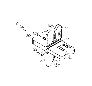
[0040] Referring to Fig. 1, a perspective view of one embodiment of a
spacer member
is shown. The spacer member includes a hub or core portion 12, with a
plurality of spacing
wings 14, 16, 18 and 20 extending outwardly away from the hub or core. The
core 12 includes
a central axis 22, and each of the wings extends away from the central axis
14.
[0041] As best seen in the end profile of Fig. 2, with the profile taken
looking along
the central axis 14, wings 14 and 16 extend from substantially opposite sides
of the hub 12 and
generally parallel to each other. Likewise, wings 18 and 20 extend from
substantially opposite
sides of the hub 12 and generally parallel to each other. Each spacing wing
defines a
respective spacing width W14, W16, W18 and W20. In the illustrated embodiment,
four
distinct spacing widths are defined (e.g., W14 = 1/16", W16 = 1/8", W18 =
3/16" and W20 =
1/4"), but other variations are possible. For example, all four of the spacing
widths could be
the same, or two or three of the spacing widths could be the same. As shown,
each spacing
wing may include indicia thereon (e.g., integrally molded therein or printed
or imprinted
thereon) that advises the user of the spacing width defined by the particular
spacing wing.
[0042] In the illustrated embodiment, spacing wings 14 and 16 lie within
or along a
common plane 24, and spacing wings 18 and 20 lie within or along a common
plane 26. The
two planes 24 and 26 are perpendicular to each other. Thus, spacing wings 14
and 16 extend
substantially perpendicular to spacing wings 18 and 20. Likewise, the spacing
wing 14 is
spaced apart from both the spacing wings 18 and 20 (by angles el and 02 of
approximately
90 degrees in each case), and the spacing wing 16 is spaced apart from both
the spacing wings
18 and 20 (by angles 03 and 04 of approximately 90 degrees in each case).
[0043] Spacing wing 14 is connected to the hub 12 via a hinge portion 30
and spacing
wing 16 is connected to the hub 12 via a hinge portion 32. The hinge portions
allow the
5
CA 02885090 2015-03-17
Attorney Docket No. 091226-00010US
spacing wings 14 and 16 to pivot, rotate or otherwise move. In this regard,
the orientation of
Figs. 1 and 2 shows the spacing member 10 in a working configuration, which is
generally
cross-shaped as described above. The working configuration is useful for
positioning and
movement of the spacer member 10 between boards 40 to define the spacing
between the
boards 40 (or tiles) as generally shown in Fig. 3. By moving the spacing wings
14 and 16, the
spacer member can be reconfigured into a collapsed configuration that is
useful for packaging
of the spacer member as reflected in Fig. 4.
[0044] In the collapsed configuration, the spacing wings 18 and 20 extend
substantially
parallel to each other, the spacing wing 14 is positioned alongside the
spacing wing 20 and the
spacing wing 16 is positioned alongside the spacing wing 18. Each hinge is
configured to
allow its associate spacing wing to pivot or rotate in either direction, so
that in an alternative
collapsed configuration the spacing wing 14 could be positioned alongside
spacing wing 18
and the spacing wing 16 could be positioned alongside spacing wing 20.
Moreover, if desired,
both spacing wings 14 and 16 could be positioned alongside the same one of the
spacing wings
18 or 20.
[0045] As noted above, the collapsed configuration of the spacer member
facilitates
packaging. In particular, considering the illustrated embodiment, where a
thickness of the
spacer member runs substantially perpendicular to the third and fourth spacer
members or the
plane 26, the thickness Tcc (Fig. 4) of the spacer member when in the
collapsed configuration
is substantially smaller than the thickness Twc (Fig. 2) of the spacer member
when in the
working configuration. By way of example, thickness Tcc may be no more than
thirty percent
(e.g., no more than twenty-five percent, nor more than twenty percent or in
some cases no
more than fifteen percent) of the thickness Twc, resulting in significantly
reduced package
volume/size.
[0046] In this regard, reference is made to Figs. 5, 6 and 7 showing
different package
assembly embodiments for the spacer member. In Fig. 5, the package assembly 50
includes a
spacer member 10 held in the collapsed configuration within a carrying space
of the package
between a panel member 52 (e.g., paperboard) and a blister member 54 (e.g.,
clear plastic).
Multiple spacer members could likewise be packaged in such a blister
arrangement. In Fig. 6,
the package assembly 60 includes one or more spacer members 10 held in the
collapsed
6
CA 02885090 2015-03-17
Attorney Docket No. 091226-00010US
configuration within a carrying space of the package between upper and lower
clamshell
members 62 and 64 that are pivotably connected at hinge 66 to enable opening
of the package.
Edges 68 of the clam shell members may include suitable inter-engaging clasp
or latch
structure to releasably hold the clamshell package in the closed condition. In
Fig. 7, the
package assembly 70 includes one or more spacer members 10 held in the
collapsed
configuration within a carrying space of a bag material 72 that includes a
closable end 74 (e.g.,
with zip or other mating closure structure). In any of the foregoing package
assembly
embodiments, additional material may be provided within the package along with
the spacer
member(s). Moreover, the packaging material for the spacer member(s) 10 may
also include
associated ties or strapping 76 (per Fig. 7) to help maintain the spacer
member in the collapsed
configuration. By way of example, plastic strap material, rubber band material
or synthetic or
natural fiber tie material may be used for the strapping 76.
[0047] Referring now to Figs. 8 and 9, exemplary living hinge structures
30 and 32 are
shown. It is contemplated that the spacer member may be of a molded plastic
material that
facilitates production of the living hinge. By way of example, polypropylene,
polyethylene,
polycarbonate, acrylonitrile butadiene styrene or another polymer (e.g., any
suitable
thermoplastic polymer) may be used. Each living hinge 30 and 32 is formed by a
narrow band
of material 80, 82 that connects the respective spacing wings 14, 16 to the
hub or core 12.
Each narrow band of material is offset slightly from the hub or core 12 by a
respective
projection 84, 86 that narrows when moving outward from the hub or core. The
projections
84, 86 help to assure that each spacing wing 14, 16 has sufficient space to
pivot a full ninety
degrees in either direction without coming into contact with the adjacent
spacing wing 18 or
20 in a manner that could tend to unduly strain the living hinge and cause
undesired breakage
(e.g., in some cases some contact may be permitted, but contact that induces
high stresses on
the hinge is avoided).
[0048] In some embodiments, the living hinges may be formed so as to bias
the
spacing wings 14, 16 toward the working positions that represent the working
configuration
(e.g., the positions shown in Fig. 2). That is, the natural tendency of the
structure due to the
material composition and/or characteristics in combination with the
configuration of the living
hinge results in a bias such that, in the absence of any external force
holding the spacer
7
CA 02885090 2015-03-17
Attorney Docket No. 091226-00010US
member in the collapsed configuration, the spacing wings 14, 16 tend to move
toward
respective positions that correspond to the working configuration. The natural
bias also helps
to keep the spacing wings 14 and 16 in their working positions, making the
spacer member
easier to use and handle during board or tile spacing. In one implementation,
where the spacer
members are formed of molded plastic, the spacer members may be manipulated
shortly after
production (e.g., while the spacer member is still warm) to assure desired
flexibility of the
living hinges. Such manipulation may involve moving each the spacing wings 14
and 16 one
or more times in order to flex the living hinges.
[0049] In the illustrated embodiment, the living hinges are formed on (i)
only two of
the four spacing wings, (ii) two spacing wings that are positioned in opposed
relationship to
each other and (iii) the two spacing wings that are the two thinnest of the
four. However,
variations are possible, including 1, 3 or 4 of the spacing wings having a
living hinge feature.
In certain implementations the thickness of the living hinge may be between
about 0.010 and
about 0.020 inches (e.g., between about 0.012 inches and about 0.017 inches).
However, other
variations are possible.
[0050] The spacer members may be packaged and sold as stand-alone items
or may be
sold in combination with other items (e.g., as a kit). By way of example, and
referring to Fig.
10, one or more spacer members 10 may be incorporated into a container 90 that
holds a
plurality of threaded fasteners 92 (e.g., of the type used for securing deck
boards in place).
The container has a closure 94 that may be used to access the fasteners 92,
and the spacer
member may typically be placed atop the fasteners for ready retrieval when the
container 90 is
initially opened. In one embodiment, the container 90 is a box member (e.g.,
of plastic) and
the closure is a lid (e.g., of plastic) on the box member. The lid may be
completely removable
and/or may have a pivotable door to access the internal compartment of the
container.
[0051] Although the above packaging examples reflect the spacing member
being
packaged in a collapsed form, it is also recognized that in some instances the
spacing member,
or at least one spacing member of multiple spacing members within a package,
could be in the
un-collapsed, working configuration. For example, the package assembly 100 of
Fig. 13, two
spacer members 10 are contained between a panel member 102 and a blister
member 104,
where dashed line 106 represents the raised portion of the blister member.
Each of the spacer
8
CA 02885090 2015-03-17
Attorney Docket No. 091226-00010US
members is lying on edge, in un-collapsed form within the package. In the
package assembly
110 of Fig. 14, eight spacer members 10 are contained between a panel member
112 and a
blister member 114, where dashed line 116 represents the raised portion of the
blister member.
Each of the spacer members is lying on edge, in collapsed form within the
package.
[0052] The dimensions of the spacer member 10 can vary widely. However,
referring
to Figs. 11 and 12, exemplary suitable dimensions for the spacer member may
include Y1
between about 1.5" and 3.0", Y2 between about 1.20" and 3.40", X1 between
about 1.5" and
3.0", X2 between about 1.20" and 3.40" and Z between about 0.50" and about
1.50". In this
regard, dimension Y1 represents the largest profile dimension from the distal
end of spacing
wing 14 to the distal end of spacing wing 16, dimension X1 represents the
largest profile
dimension from the distal end of spacing wing 18 to the distal end of spacing
wing 20,
dimension Y2 represents the smallest profile dimension from the distal end of
spacing wing 14
to the distal end of spacing wing 16, dimension X2 represents the smallest
profile dimension
from the distal end of spacing wing 18 to the distal end of spacing wing 20
and dimension Z
represents the dimension of the hub or core and, in the illustrated
embodiment, the spacing
wings, in a direction parallel to the axis 14 of the hub/core. With respect to
dimensions Y2
and X2, it is noted that the distal end of each spacing wing 14, 16, 18 and 20
includes a
recessed region 100, 102, 104 and 106, and the dimensions Y2 and X2 are
measured from
recess bottom to recess bottom. Generally, it is contemplated that dimensions
X1 and Y1 will
be substantially the same, and dimensions X2 and Y2 will be substantially the
same, but
variations are possible.
[0053] In the illustrated embodiment, as best seen in Figs. 3 and 11, the
recessed
regions help identify a suitable location at which a screw-type fastener 200
can be placed for
fasting down a deck board 40 into a joist 202. In this regard, it is therefore
preferred that the
dimensions X2 and Y2 be at least 1.0 inch or more, so as to assure that the
screw is not
positioned too close to the edge of the board 40. Thus, the spacing member
provides a deck
board installation methodology that includes (a) positioning a first deck
board on a support
arrangement (e.g., an underlying joist system), (b) positioning a second deck
board on the
support arrangement, (c) positioning the spacing member with a first spacing
wing extending
downward between the first and second deck boards, (d) moving at least one of
the boards so
9
CA 02885090 2015-03-17
Attorney Docket No. 091226-00010US
that the first spacing wing defines a gap size between the first and second
deck boards, (e)
placing a first screw into the first deck board to secure the first deck board
to the support
arrangement, where the first screw is placed at a location defined by a recess
at the end of a
second spacing wing, and (0 placing a second screw into the second deck board
to secure the
second deck board to the support arrangement, where the second screw is placed
at a location
defined by a recess at the end of a third spacing wing. The spacing member can
then be slid
along the gap between the first and second deck boards to another location
where steps (e) and
(f) can be repeated.
[0054] It is to be clearly understood that the above description is
intended by way of
illustration and example only, is not intended to be taken by way of
limitation, and that other
changes and modifications are possible. For example, while the use of living
hinges is
primarily described to facilitate movement of the spacer member between
working and
collapsed configurations, other structures could be used (e.g., actual hinges
formed by
interconnecting components).
[0055] What is claimed is: