Note : Les descriptions sont présentées dans la langue officielle dans laquelle elles ont été soumises.
CA 02887122 2016-07-14
PREFABRICATED MOLD FOR CONSTRUCTION OF CONCRETE
PAVEMENT
CROSS-REFERENCE TO RELATED APPLICATION
This application claims priority to and the benefit of Korean Patent
Application No. 2013-0030119, filed on March 21, 2013.
BACKGROUND
1. Field of the Invention
The present invention relates to a prefabricated mold for construction of a
concrete pavement capable of being easily assembled, installed and
disassembled and
being repeatedly re-used, and more particularly, to a mold capable of butt-
coupling
structures of molds installed at both sides of a roadbed in which ground works
are
finished before deposition and aging of a slab of concrete, the molds being
able to be
arranged in a horizontal direction and/or a vertical direction, and capable of
being
constructed by injection-molding the molds using a synthetic resin material
and
installing the injection-molded molds in a prefabricated manner, and the molds
being
formed so that fixing rod insertion holes can be formed through an upper
central
region of the mold and formed through the coupling segments formed at both
sides
of the mold, and coupling grooves can be formed in a plural number to protrude
from
an inner surface of the mold to be coupled to protrusions formed at finishing
plates.
2. Discussion of Related Art
1
CA 02887122 2016-07-14
Generally, a concrete pavement is constructed by performing a flattening
process as a ground work on roadbeds, installing molds according to the width
of a
road, depositing and aging slabs of concrete through a finishing process, and
disassembling the molds to construct the concrete pavement when these
operations
are completed. In this case, molds formed of woods and metals are widely used
as
the molds used for construction of the concrete pavement.
The molds used to construct conventional concrete pavements can be mainly
divided into wooden veneer molds and metal molds according to the shapes of
the
molds.
The wooden veneer molds are constructed by installing molds, in which
gradient posts are fixed in an inner side (a road surface) of a sheet of
veneer with
nails, at both sides of a road according to the width of the load, installing
rebar at the
rear end of the molds on the ground so as to primarily support the molds and
obliquely installing supporting posts to secondarily support the molds.
As disclosed in Korean Utility Model No.: 20-0263829 (a steel sheet mold
for construction of concrete pavement) using a galvanized steel sheet, the
metal
molds can be supported by pressing a bent portion and inclined plane formed at
an
upper surface of a steel sheet body using a press, coupling connection posts
and
supporting posts to each other using nails, fixing the connection posts and
the
supporting posts in the rear of the steel sheet body, and putting rebar into
the ground,
and fixing the connection posts and the supporting posts in the rebar using
large nails.
In addition to the steel sheet, the metal molds are formed of various kinds of
metals such as galvanized steel sheet, aluminum, magnesium, and the like.
The conventional veneer molds configured thus has problems in that woods
are expensive, and a great deal of work time is required since the molds are
manually
2
CA 02887122 2016-07-14
coupled and supported by workers, and thus a lot of manpower are also
required, and
also that the woods are easily broken during delivery, assembly and
disassembly due
to their characteristics, and thus a great deal of maintenance and repair
costs are
required, and the woods cannot be used continuously and repeatedly. Although
the
metal molds has an advantage in that they can be used semi-permanently in an
economic aspect, they have problems in that they are very heavy, and thus they
cannot be easily delivered, assembled and disassembled, and great deals of
manpower and work time are required since the same subsequent processes as in
the
woods are required upon installation of the metal molds.
To solve the prior-art problems, Korean Utility Model No.: 20-0433737 (a
mold for pavement of cement concrete) in which a veneer sheet for molds, a
hard
fiber board, a synthetic resin, an aluminum panel, a steel sheet and the like
may be
selectively used as the mold is proposed.
The mold disclosed in the utility model is configured to include a body
formed in a plate shape in order to divided a predetermined space, a hinge
portion
formed to engage both sides of the body with other bodies, a hinge shaft hole
formed
through the hinge portion, and a piling hole formed through a protrusion
formed in
the rear surface of the body to support the body on the ground.
Although the mold disclosed in the utility model has advantages in that the
mold is formed of various kinds of materials, and thus it can be re-used, it
has
problems in that it cannot be easily delivered and installed due to its entire
heavy
weight derived from the structural characteristics, and that the hinge portion
configured to couple one mold to another mold may be damaged or deformed when
the structures of the hinge portions is repeatedly used in a state where the
hinge
3
CA 02887122 2015-04-07
portions are engaging crisscross, which makes it difficult to easily assemble
and
disassemble the molds.
SUMMARY OF THE INVENTION
Accordingly, the present invention is designed to solve the problems of the
prior art, and therefore it is an object of the present invention to provide a
prefabricated mold capable of being easily assembled and disassembled since
both
upper and lower ends of molds are butt-coupled to each other, minimizing the
weight
of the molds since a plurality of coupling grooves are formed from an inner
surface
of the mold having an internal space formed therein to be coupled to
protrusions of
finishing plates, being easily manufactured since the mold manufactured by
injection-molding a synthetic resin configured to enhance strength of the mold
since
the coupling grooves formed from the inner surface of the mold serve as a
reinforcing material is used, being re-used semi-permanently due to excellent
strength and minimal weight, being easily delivered, assembled and
disassembled,
reducing a work time with minimal manpower upon assembly and disassembly of
the
molds which are manufactured in a prefabricated manner, and minimizing the
manufacturing cost and the maintenance and repair costs as well.
According to an aspect of the present invention, there is provided a
prefabricated mold for construction of a concrete pavement which is used for
roads
constructed by depositing and aging a slab of concrete. Here, the
prefabricated mold
includes coupling segments taperedly installed at both upper and lower ends of
the
mold to be butt-coupled to each other, fixing rod insertion holes formed
through an
upper central region of the mold and formed through the coupling segments
formed
at both sides of the mold, coupling grooves installed in a plural number to
protrude
4
CA 02887122 2015-04-07
from an inner surface of the mold having an internal space formed therein,
finishing
plates having a plurality of protrusions formed therein to be inserted into
the
coupling grooves, fixing rod insertion holes formed at the mold having a slope
segment installed at a front upper portion thereof by injection-molding the
mold
using a synthetic resin material, and fixing rods inserted respectively into
the fixing
rod insertion holes to fix the mold on the ground.
In this case, the mold may be coupled to another mold in a horizontal
direction so that the coupling segments can be butt-coupled to each other in a
transverse direction so as to insert the fixing rods into the fixing rod
insertion holes,
1 0 respectively.
BRIEF DESCRIPTION OF THE DRAWINGS
The above and other objects, features and advantages of the present
invention will become more apparent to those of ordinary skill in the art by
describing in detail exemplary embodiments thereof with reference to the
accompanying drawings, in which:
FIG. 1 is an exploded perspective view showing the entire structure of a
mold according to one exemplary embodiment of the present invention;
FIG. 2 is a use state diagram showing a coupling structure of a mold
according to one exemplary embodiment of the present invention; and
FIG. 3 is a cross-sectional view showing the mold according to one
exemplary embodiment of the present invention.
DETAILED DESCRIPTION OF EXEMPLARY EMBODIMENTS
5
CA 02887122 2015-04-07
Exemplary embodiments of the present invention will be described in detail
below with reference to the accompanying drawings. While the present invention
is
shown and described in connection with exemplary embodiments thereof, it will
be
apparent to those skilled in the art that various modifications can be made
without
departing from the scope of the invention.
Unless specifically stated otherwise, all the technical and scientific terms
used in this specification have the same meanings as what are generally
understood
by a person skilled in the related art to which the present invention belongs.
In
general, the nomenclatures used in this specification and the experimental
methods
described below are widely known and generally used in the related art.
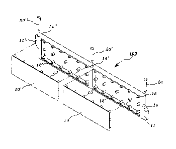
FIG. 1 is an exploded perspective view showing the entire structure of a
mold according to one exemplary embodiment of the present invention. Here, the
mold has a structure in which coupling segments are formed at both upper and
lower
ends of the mold, fixing rod insertion holes are formed through the coupling
segments formed at the both upper and lower ends and central region of the
mold,
and protrusions of finishing plates are coupled to coupling grooves formed in
an
inner surface of the mold. FIG. 2 is a use state diagram showing a coupling
structure
of a mold according to one exemplary embodiment of the present invention.
Here,
one mold is coupled to another mold in a transverse direction to fix the
molds. FIG. 3
is a cross-sectional view showing the mold according to one exemplary
embodiment
of the present invention.
In the mold used for roads constructed by depositing and aging a slab of
concrete, coupling segments 11 and 11' may be taperedly installed at both
upper and
lower ends of the mold 100 to be butt-coupled to each other, fixing rod
insertion
holes 14, 14' and 14" may be formed through an upper central region of the
mold
6
CA 02887122 2015-04-07
100 and formed through the coupling segments 11 and 11' formed at both sides
of the
mold 100, coupling grooves 12 and 12' may be installed in a plural number to
protrude from an inner surface of the mold 100 having an internal space formed
therein, finishing plates 10 and 10' may have a plurality of protrusions 13
and 13'
formed therein to be inserted into the coupling grooves 12 and 12', fixing rod
insertion holes 14, 14' and 14" formed at the mold 100 having a slope segment
15
installed at a front upper portion thereof by injection-molding the mold 100
using a
synthetic resin material, and fixing rods 20, 20' and 20" inserted
respectively into the
fixing rod insertion holes 14, 14' and 14" to fix the mold 100 on the ground.
In this case, the mold 100 may be coupled to another mold 100' in a
horizontal direction so that the coupling segments 11 and 11' can be butt-
coupled to
each other in a transverse direction to insert the fixing rods 20, 20' and 20"
into the
fixing rod insertion holes 14, 14' and 14", respectively.
According to exemplary embodiments of the present invention configured
thus, the mold 100 which can be easily manufactured, exhibit high strength, be
lightweight, and be used semi-permanently since the mold injection-molded from
a
synthetic resin material is used when a road is constructed by depositing and
aging a
slab of concrete, can be easily installed, assembled and disassembled, and can
be
useful in reducing a work time with minimal manpower upon assembly and
disassembly of the molds which are manufactured in a prefabricated manner and
minimizing the manufacturing cost and the maintenance and repair costs.
As shown in FIG. 1, the mold 100 has a structure in which the coupling
segments 11 and 11' are installed at both upper and lower ends of the mold
100. In
this case, when one side of each of the coupling segments 11 and I 1 ' is
installed at
an upper portion of the mold 100, and the other side of each of the coupling
segments
7
CA 02887122 2015-04-07
11 and 11' is installed at a lower portion of the mold 100 to install the
plurality of
molds 100, the coupling segments 11 and 11' may be butt-coupled to each other.
Since an inner space is formed in the mold 100 and a plurality of coupling
grooves 12 and 12' are formed in the inner space, the entire weight of the
mold 100
may be reduced, and the coupling grooves 12 and 12' installed to protrude from
the
inner surface of the mold 100 may serve as a reinforcing material.
The plurality of protrusions 13 and 13' formed at the finishing plates 10 and
10' may be inserted and coupled to the coupling grooves 12 and 12',
respectively, to
further reinforce the mold 100 while regularly arranging the rear ends of the
molds.
As shown in FIG. 2, the coupling segments 11 and 11' installed at both sides
of the molds 100 and 100' may be butt-coupled to each other, and the fixing
rods 20,
20' and 20" may be fixed on the ground, respectively, using the fixing rod
insertion
holes 14, 14' and 14" formed through an upper central region of the mold 100
and
formed through the coupling segments 11 and 11' formed at both sides of the
mold
100 so as to support the molds 100 and 100' during a process of depositing and
aging
a slab of concrete in the molds 100 and 100'.
As shown in FIG. 3, the protrusions 13 and 13' of the finishing plates 10 and
10' may be inserted and coupled to the coupling grooves 12 and 12' in the
inner
space of the mold 100 to reinforce hardness of the mold 100, and the slope
segment
15 may be formed at a front upper portion of the mold 100, and thus the
interface
between the molds 100 and 100' may be formed during a finishing process of
depositing and flattening a slab of concrete, which makes it easy to perform
pavement works easily.
When both lateral surfaces of the molds 100 and 100' have to be elevated to
a certain height due to sections and geographies requiring the height of a
concrete
8
CA 02887122 2015-04-07
pavement, the molds 100 and 100' may be stacked, and the fixing rods 20, 20'
and
20" may be longitudinally enlarged accordingly according to the stacked molds
100
and 100' so that the molds 100 and 100'can be fixed on the ground.
Therefore, the mold 100 according to the exemplary embodiments of the
present invention can be useful in being simply manufactured since the mold
100 is
manufactured by injection-molding a synthetic resin using a method of coupling
the
finishing plates during construction of a concrete pavement, improving the
esthetic
sense, being easily manufactured, exhibiting high strength, being lightweight,
and
being used semi-permanently. Also, the mold 100 according to the exemplary
=
embodiments of the present invention can be useful in being easily delivered,
assembled and disassembled upon construction of the concrete pavement,
reducing a
work time with minimal manpower since the molds are manufactured in a
prefabricated manner, and minimizing the manufacturing cost and the
maintenance
and repair costs.
It will be apparent to those skilled in the art that various modifications can
be
made to the above-described exemplary embodiments of the present invention
without departing from the scope of the invention. Thus, it is intended that
the
present invention covers all such modifications provided they come within the
scope
of the appended claims and their equivalents.
9