Sélection de la langue

Search

Sommaire du brevet 2887275 

Énoncé de désistement de responsabilité concernant l'information provenant de tiers

Une partie des informations de ce site Web a été fournie par des sources externes. Le gouvernement du Canada n'assume aucune responsabilité concernant la précision, l'actualité ou la fiabilité des informations fournies par les sources externes. Les utilisateurs qui désirent employer cette information devraient consulter directement la source des informations. Le contenu fourni par les sources externes n'est pas assujetti aux exigences sur les langues officielles, la protection des renseignements personnels et l'accessibilité.

Disponibilité de l'Abrégé et des Revendications

L'apparition de différences dans le texte et l'image des Revendications et de l'Abrégé dépend du moment auquel le document est publié. Les textes des Revendications et de l'Abrégé sont affichés :

  • lorsque la demande peut être examinée par le public;
  • lorsque le brevet est émis (délivrance).
(12) Brevet: (11) CA 2887275
(54) Titre français: EMBRAYAGE DISTANT
(54) Titre anglais: REMOTE LOCATED CLUTCH
Statut: Accordé et délivré
Données bibliographiques
(51) Classification internationale des brevets (CIB):
  • B60K 17/04 (2006.01)
  • B60F 05/00 (2006.01)
  • B60K 17/02 (2006.01)
(72) Inventeurs :
  • TIRY, MICHAEL J. (Etats-Unis d'Amérique)
(73) Titulaires :
  • ARCTIC CAT INC.
(71) Demandeurs :
  • ARCTIC CAT INC. (Etats-Unis d'Amérique)
(74) Agent: PIASETZKI NENNIGER KVAS LLP
(74) Co-agent:
(45) Délivré: 2022-04-12
(22) Date de dépôt: 2015-04-01
(41) Mise à la disponibilité du public: 2015-10-04
Requête d'examen: 2020-03-13
Licence disponible: S.O.
Cédé au domaine public: S.O.
(25) Langue des documents déposés: Anglais

Traité de coopération en matière de brevets (PCT): Non

(30) Données de priorité de la demande:
Numéro de la demande Pays / territoire Date
14/245901 (Etats-Unis d'Amérique) 2014-04-04

Abrégés

Abrégé français

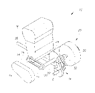
Un ensemble dentraînement comprend une transmission à variation continue (TVC) et un moteur, la TVC étant positionnée à larrière (ou à lavant) du moteur. Un mécanisme dentraînement auxiliaire raccorde un arbre de transmission de la TVC à un vilebrequin du moteur. Le mécanisme dentraînement auxiliaire est une courroie ou une chaîne. Larbre de transmission est essentiellement parallèle au vilebrequin et décalé longitudinalement. Par conséquent, la largeur de lensemble dentraînement est réduite par rapport aux VTT ayant la TVC adjacente au moteur. Une méthode de fabrication dun VTT ayant lensemble dentraînement est aussi décrite.


Abrégé anglais

A drive package includes a remote located CVT and a motor where the CVT is positioned rearward (or forward) of the motor. An auxiliary drive mechanism couples a drive shaft of the CVT to a crankshaft of the motor. The auxiliary drive mechanism is a belt or chain. The drive shaft is substantially parallel to, and longitudinally offset from, the crankshaft. Thus, the width of the drive package is reduced as compared to ATVs having a CVT located adjacent the motor. A method of making an ATV with the drive package is provided.

Revendications

Note : Les revendications sont présentées dans la langue officielle dans laquelle elles ont été soumises.


THE EMBODIMENTS OF THE INVENTION IN WHICH AN EXCLUSIVE
PROPERTY OR PRIVILEGE IS CLAIMED ARE DEFINED AS FOLLOWS:
1. A vehicle having a fore-and-aft axis and a side-to-side axis, the
vehicle
comprising:
a motor having an output shaft;
a constantly variable transmission (CVT) having a drive clutch secured to a
drive shaft rotatably coupled to the motor output shaft via a drive mechanism
extending
transverse to the motor output shaft, the drive mechanism being a belt, chain,
or shaft,
the CVT drive shaft being longitudinally and/or vertically offset from the
motor output
shaft and substantially parallel to the motor output shaft;
the CVT having a driven clutch coupled to the drive clutch, the driven clutch
having a driven shaft offset from and substantially parallel to the motor
output shaft,
wherein the drive shaft and the driven shaft are disposed on a same fore or
aft side of
the motor output shaft; and
an output member rotatably coupled to and driven by the CVT driven shaft, the
output member driving a ground engaging member of the vehicle, the output
member
passing under the drive shaft.
2. The vehicle of Claim 1, wherein the motor output shaft is oriented
transverse to
a longitudinal axis of the vehicle, the motor including a casing and the drive
mechanism
being secured to the motor output shaft external to said motor casing.
3. The vehicle of Claim 2, further comprising a secondary drive mechanism
rotatably coupled to the CVT drive shaft for providing motive power to at
least one
auxiliary device.
4. The vehicle of Claim 1, wherein the drive mechanism comprises a drive
belt,
the motor output shaft having a motor pulley secured thereto, said motor
pulley
engaging the drive belt, further wherein the CVT drive shaft includes a drive
pulley
engaged with the drive belt.
- 10 -

5. The vehicle of Claim 4, wherein the drive belt extends from an end of
the motor
output shaft at a lateral side of the motor, the belt extending in a fore-aft
direction.
6. The vehicle of Claim 1, wherein the motor output shaft has a
longitudinal axis
spatially forward of, a longitudinal axis of the CVT drive shaft.
7. The vehicle of Claim 1, further comprising a stator coupled to the CVT
drive
shaft.
8. The vehicle of Claim 1, further comprising a centrifugal clutch
entrained
between the motor output shaft and the CVT drive shaft.
9. The vehicle of Claim 1, wherein the driven shaft is rotatably coupled to
another
output member for rotating a rear axle coupled to a rear pair of ground
engaging
members.
10. The vehicle of Claim 1, further comprising a supplemental gear attached
to the
CVT drive shaft for powering at least one device attachable to the vehicle.
11. The vehicle of Claim 1, wherein the motor is an internal combustion
engine and
the motor output shaft is a crankshaft.
12. The vehicle of Claim 1, wherein the vehicle is an all-terrain vehicle
with at least
four wheels drivingly entrained with the CVT driven shaft.
13. A drive package for an all-terrain vehicle having at least one pair of
ground
engaging members, the drive package comprising:
a motor having an output shaft, the motor output shaft having a lateral end
extending from the motor;
a coupling drive mechanism rotatably coupled to the lateral end of the motor
output shaft and extending transverse to a longitudinal axis of the motor
output shaft;
- 11 -

a drive shaft of a constantly variable transmission (CVT), the drive shaft
rotatably coupled to the coupling drive mechanism, the CVT drive shaft being
substantially parallel to the motor output shaft; and
an output member rotatably coupled to and driven by a drive shaft of the CVT,
the output member driving a ground engaging member of the at least one pair of
ground
engaging members of the vehicle, the output member passing under the drive
shaft;
wherein the drive shaft and the driven shaft are disposed on a same fore or
aft
side of the motor output shaft.
14. The drive package of Claim 13, wherein coupling drive mechanism is a
belt, a
chain or a shaft.
15. The drive package of Claim 13, further comprising a centrifugal clutch
rotatably
attached to the CVT drive shaft and entrained with the coupling drive
mechanism.
16. The drive package of Claim 13, wherein the coupling drive mechanism is
a belt,
each of the motor output shaft and the CVT drive shaft having a pulley thereon
engaging the belt.
- 12 -

Description

Note : Les descriptions sont présentées dans la langue officielle dans laquelle elles ont été soumises.


CA 02887275 2015-04-01
REMOTE LOCATED CLUTCH
FIELD OF THE INVENTION
[0001] The present invention relates to a drive package for vehicles, and
more
particularly, to a drive package with a remote located continuously variable
transmission
(CVT) for an all-terrain vehicle.
BACKGROUND OF THE INVENTION
[0002] Vehicles, particularly straddle-type all-terrain vehicles (ATVs),
have
limited area to house the drive components of the vehicle, such as a motor and
a
transmission. Presently, most all-terrain vehicles have a CVT with a drive
clutch
positioned laterally of the motor. The crankshaft of the motor extends to or
is coupled to
the drive clutch of the CVT, such that the drive clutch is laterally adjacent
(typically to
the left or right) of the motor. This configuration consumes a certain width
below an
operator riding area, such as the foot-wells (or seat) of the vehicle, because
the motor and
the CVT are positioned primarily below the riding area upon which a rider
sits. The
result is that the foot-wells of the vehicle are spaced apart by the certain
distance dictated
by of the drive clutch of the CVT being adjacent the motor. It is advantageous
to reduce
the width of the drive package, in part, because the distance between the foot-
wells, and
the resulting vehicle width, are important design factors considering the
various sizes of
riders, ergonomic factors, and the width regulations that apply to certain all-
terrain
vehicles.
- 1 -

CA 02887275 2015-04-01
SUMMARY OF THE INVENTION
[0003] The present invention overcomes the disadvantages of the prior-art
drive
systems by providing an all-terrain vehicle with a remote-located CVT
positioned
rearward (or forward) of a motor. An auxiliary drive mechanism (e.g., a belt)
couples the
CVT to the motor. As such, the drive package width is reduced, and therefore,
the foot-
wells of the vehicle are closer together as compared to a comparable ATV with
a drive
clutch driven directly by the crankshaft.
[0004] In a preferred embodiment, an ATV includes a front pair of ground
engaging members (e.g., wheels) and a rear pair of ground engaging members (at
least
one pair for moving the vehicle). Naturally, the ATV includes a motor having a
crankshaft for transferring rotational power to a transmission for rotation of
the ground
engaging members. Here, the vehicle includes a CVT with a drive clutch shaft
rotatably
coupled to the crankshaft and positioned either rearward or forward of the
crankshaft. In
either configuration, the drive clutch shaft is preferably substantially
parallel to, and
longitudinally and/or vertically offset from, the crankshaft. In the preferred
embodiment,
the drive clutch shaft is positioned rearward the crankshaft (Figures 1 and
2). An
auxiliary drive mechanism rotatably couples the drive clutch shaft to the
crankshaft. The
auxiliary drive mechanism may be one of a belt, chain, or shaft, but
preferably a belt.
Because the auxiliary drive mechanism can be a relatively thin belt, for
example, the
drive package width is reduced because the CVT is positioned rearward the
motor (Figure
2), as opposed to on one side of the motor as with many existing ATVs.
[0005] As with many CVTs, the drive clutch is attached to a driven clutch
by a
CVT belt. The driven clutch is coupled to an output member and a gearbox
system for
- 2 -

CA 02887275 2015-04-01
rotating one or both of the front pair and the rear pair of ground engaging
members.
Typically, the gearbox system would be a transaxle for rotation of a rear axle
coupled to
the rear pair of ground engaging members (Figure 2).
[0006] In some embodiments, the ATV includes a secondary drive mechanism
rotatably coupled to one of the crankshaft and the drive clutch shaft for
providing motive
power to at least one auxiliary device attachable to the ATV. In some
embodiments, a
stator is secured to the side of the motor at the end of the crankshaft on an
opposing side
of the motor from the auxiliary drive mechanism to provide electrical energy
from the
rotation of the crankshaft. Alternatively, the stator assembly can be attached
to the drive
clutch shaft (which is in continuous rotation with the crank shaft) to further
reduce the
width of the entire drive package.
[0007] In some embodiments, a centrifugal clutch may be attached to one
of the
crankshaft and the drive clutch shaft. As such, the centrifugal clutch
provides
engagement of either the crankshaft or the drive clutch shaft (as the case may
be) as
revolutions per minute exceed a certain threshold.
[0008] A method is provided for making a drive package for an ATV having
a
front pair and a rear pair of ground engaging members. The method includes, in
any
particular suitable order, attaching a motor having a crankshaft to the
vehicle and
coupling an auxiliary drive mechanism (e.g., a belt) to the crankshaft, so
that the auxiliary
drive mechanism is rotatably drivable by the crankshaft. The method further
includes
positioning a drive shaft of a CVT rearward of the crankshaft, and coupling
the auxiliary
drive mechanism to the drive shaft. Accordingly, rotation of the crankshaft
causes
- 3 -

CA 02887275 2015-04-01
movement of the auxiliary drive mechanism, thereby causing rotation of the
drive shaft to
move one or both of the front pair or rear pair ground engaging members.
BRIEF DESCRIPTION OF THE DRAWINGS
[0009] Preferred and alternative examples of the present invention are
described
in detail below with reference to the following drawings:
[0010] Figure 1 is an isometric view of a drive package of the present
invention;
[0011] Figure 2 is a top view of an ATV with the drive package of Figure
1; and
[0012] Figure 3 is a left side view of the ATV of Figure 2.
- 4 -

CA 02887275 2015-04-01
DETAILED DESCRIPTION OF THE PREFERRED EMBODIMENT
[0013] Figure 1 shows a drive package 10 for an ATV 12 (Figures 2 and 3)
in a
preferred embodiment. The drive package 10 includes a motor M having a
crankshaft 14,
in a similar manner to many motors and crankshafts on ATVs. Attached to the
crankshaft
14 is a first pulley or gear 16. Rotatably coupled to the first gear 16 is an
auxiliary drive
mechanism 18, such as a belt or chain, extending from a lateral end of the
crankshaft 14.
A second pulley or gear 20 is also rotatably coupled to the auxiliary drive
mechanism 18.
Attached to the second gear 20 is a drive shaft 22, such as a drive clutch
shaft. The first
gear 16, the second gear 20, and the auxiliary drive mechanism 18 may be
covered by a
housing 24. As the motor M rotates the crankshaft 14 and the gear 16 rotate in
a counter-
clockwise direction, for example, as the auxiliary drive mechanism 18 is
translated and
thereby rotates the gear 20 and drive shaft 22 in the same direction.
[0014] The drive shaft 22 is drivingly engaged to a CVT 26. The CVT 26
includes a drive clutch 28 attached to the drive shaft 22. The drive clutch 28
is rotatably
coupled to a driven clutch 30 by a CVT belt 25 (Figure 3). A driven shaft 32
is attached
to the driven clutch 30 and coupled to a set of gears 34 (or a gearbox 34;
Figure 2) for
transferring rotational energy to a rear axle and to a front drive member 36,
which is
coupleable to a front pair of wheels (Figure 2). In operation, as the drive
shaft 22 is
rotated by the crankshaft 14 via the auxiliary drive mechanism 18, the drive
clutch 28
rotates the CVT belt 25 that rotates the driven clutch 30, and consequently
rotates the
driven shaft 32. The driven shaft 32 may cause rotation of either or both of a
front axle or
rear axle of a vehicle (e.g., the vehicle of Figure 2).
- 5 -

CA 02887275 2015-04-01
[0015] Of importance, the CVT 26 is positioned rearward of the motor M
and
crankshaft 14, in the preferred embodiment. The CVT 26 is coupled to the motor
M by
the auxiliary drive mechanism 18. Because the auxiliary drive mechanism does
not
include the relatively wide clutches of a CVT, the drive package width (or
envelope
width) of the package 10 is reduced as compared to existing packages where the
drive
clutch is immediately adjacent the left side of the motor. The result is a
drive package
that has a noticeably reduced width as compared to existing package
configurations.
[0016] Figure 2 is a top view of the vehicle 12 having mounted thereto
the drive
package 10 described with reference to Figure 1. The vehicle 12 includes a
frame 38
(schematically shown), a front axle 40, and a front pair of ground engaging
members 42
(e.g., wheels in this example). A rear axle 46 is also coupled to the frame 38
and is
coupled to a rear pair of ground engaging members 44. From this view, it will
be
appreciated that the drive clutch shaft 22 is longitudinally offset from the
crankshaft 14.
Thus, the crankshaft 14 has a longitudinal axis A that is substantially
parallel to, and
spatially forward of, a longitudinal axis B of the drive shaft 22. Thus, the
crankshaft 14 is
oriented transverse to a longitudinal axis of the vehicle. This provides the
advantage of
providing a predefined envelope E with a predefined width W because the drive
clutch 28
is not positioned laterally adjacent the motor M and crankshaft 14, as with
existing
systems. Here, the drive clutch 28 is rearward the motor M in the preferred
embodiment
while the crankshaft still exits the side of the engine for transfer of
rotational power.
Alternatively, the drive clutch 28 and CVT 26 may be positioned forward of the
motor M.
In some embodiments, depending upon the type of motor used, width W is between
16
inches and 23 inches. In a preferred embodiment, width W is 16 inches or less.
One
- 6 -

CA 02887275 2015-04-01
preferred example, with a single cylinder engine, width W is preferably 21.5
inches, or
less in some configurations. Using a parallel twin cylinder engine, width W is
preferably
23 inches, or less in some configurations.
[0017] As discussed with reference to Figure 1, the driven clutch 30
rotates the
driven shaft 32, which is coupled to the gearbox 34. In a preferred
embodiment, the
gearbox 34 is a transaxle coupled to the rear axle 46 (gearbox 34 is
longitudinally
exaggerated in Figure 2 for purposes of illustrating the configuration of the
CVT rearward
the motor). A half shaft of the rear axle will typically extend from each side
of the
gearbox 34 to the right and left wheels. As will be appreciated from Figure 2,
each power
transfer linkage from the crankshaft 14, to the drive shaft 22, to the driven
shaft 32, to the
rear axle 46, are each zero degree power transfer linkages relative to each
other. Thus,
the crankshaft 14, drive shaft 22, driven shaft 32, gears of gearbox 34
(Figure 1), and rear
axle 46 each have an axis of rotation substantially parallel to each other
(respectively
labeled A, B, C, D, and E). Such configuration is advantageous because it
improves the
engine efficiency by minimizing energy losses due to zero-degree power
transfer linkages
from the crankshaft 14 all the way to the axle 46, for example.
[0018] A left foot-well 47 and a right foot-well 49 are disposed on
either side of
the predefined envelope E. Because the predefined width W is 21.5 inches or
less, in a
preferred embodiment, the foot-wells 47 and 49 are positionable closer
together than with
existing ATVs. Not only is such spacing ergonomically comfortable, the spare
spacing
provides room for other vehicle features, including reduced overall width.
[0019] In some embodiments, a supplemental gear 48 is attached to the
drive
shaft 22, and a secondary drive mechanism 50 is rotatably coupled to the
supplemental
- 7 -

CA 02887275 2015-04-01
gear 48 on drive shaft 22 for providing power to at least one auxiliary device
X attachable
to the vehicle 12. The at least one auxiliary device X may be one or more of a
water
pump, oil pump, compressor, or other device that requires power transfer from
the
crankshaft of the engine. Advantageously, attaching such devices to the drive
clutch shaft
(instead of the crankshaft) further reduces the overall width of the drive
package. In some
embodiments, a centrifugal clutch 51 is coupled to the drive shaft 22 and is
actuated at a
threshold rotational speed of the drive shaft 22. Of course, an upstream shaft
and a
downstream shaft (in the drive train sense) would be attached to either side
of the
centrifugal clutch 51, as with a typical centrifugal clutch configuration. In
the
configuration shown with the supplemental gear 48 upstream of the centrifugal
clutch 51,
during relatively low rpms (e.g., when the motor idles) the supplemental gear
48 is
rotated but the centrifugal clutch 51 is not yet actuated. In other
embodiments (not shown
on the figures), the supplemental gear 48 can be positioned downstream the
centrifugal
clutch 51 such that the supplemental gear 48 is not rotated until the
centrifugal clutch 51
engages as rotational speed reaches the threshold.
[0020] In some embodiments, a stator 52 is coupled to the crankshaft 14
on an
opposing side on the motor M from the auxiliary drive mechanism 18. The stator
52
forms part of an alternator to produce electricity for vehicle functions such
as for
powering electrical devices of the ATV.
100211 In some embodiments, the gearbox 34 is coupled to the axle 46
(typically
two half shafts) and the rear pair of ground engaging members 44 for two-wheel
or four-
wheel drive operation of the vehicle 12. It will be appreciated that the
preferred drive
configuration between the driven clutch 30 and the rear pair of ground
engaging members
- 8 -

CA 02887275 2015-04-01
44 is a common transaxle configuration. Alternatively, a separate rear drive
case may
extend from a transmission to drive the rear wheels.
[0022] Figure 3 shows a left side view of the ATV of Figure 2. As can be
appreciated from this view, the CVT 26 is positioned rearward the motor M.
Accordingly, the drive shaft 22 coupled to the drive clutch 28 is positioned
rearward and
spatially separate from the crankshaft 14.
[0023] While the preferred embodiments of the invention have been
illustrated
and described, as noted above, many changes can be made without departing from
the
spirit and scope of the invention. Accordingly, the scope of the invention is
not limited by
the disclosure of the preferred embodiment. Instead, the invention should be
determined
entirely by reference to the claims that follow.
- 9 -

Dessin représentatif
Une figure unique qui représente un dessin illustrant l'invention.
États administratifs

2024-08-01 : Dans le cadre de la transition vers les Brevets de nouvelle génération (BNG), la base de données sur les brevets canadiens (BDBC) contient désormais un Historique d'événement plus détaillé, qui reproduit le Journal des événements de notre nouvelle solution interne.

Veuillez noter que les événements débutant par « Inactive : » se réfèrent à des événements qui ne sont plus utilisés dans notre nouvelle solution interne.

Pour une meilleure compréhension de l'état de la demande ou brevet qui figure sur cette page, la rubrique Mise en garde , et les descriptions de Brevet , Historique d'événement , Taxes périodiques et Historique des paiements devraient être consultées.

Historique d'événement

Description Date
Lettre envoyée 2022-04-12
Inactive : Octroit téléchargé 2022-04-12
Accordé par délivrance 2022-04-12
Inactive : Page couverture publiée 2022-04-11
Préoctroi 2022-01-24
Inactive : Taxe finale reçue 2022-01-24
Un avis d'acceptation est envoyé 2022-01-18
Lettre envoyée 2022-01-18
Un avis d'acceptation est envoyé 2022-01-18
Inactive : Approuvée aux fins d'acceptation (AFA) 2021-11-24
Inactive : Q2 réussi 2021-11-24
Modification reçue - réponse à une demande de l'examinateur 2021-10-06
Modification reçue - modification volontaire 2021-10-06
Rapport d'examen 2021-10-04
Inactive : Rapport - Aucun CQ 2021-09-22
Modification reçue - réponse à une demande de l'examinateur 2021-08-11
Modification reçue - modification volontaire 2021-08-11
Rapport d'examen 2021-07-05
Inactive : Rapport - Aucun CQ 2021-06-24
Représentant commun nommé 2020-11-07
Requête pour le changement d'adresse ou de mode de correspondance reçue 2020-04-27
Modification reçue - modification volontaire 2020-04-27
Lettre envoyée 2020-04-01
Modification reçue - modification volontaire 2020-03-24
Exigences pour une requête d'examen - jugée conforme 2020-03-13
Requête d'examen reçue 2020-03-13
Toutes les exigences pour l'examen - jugée conforme 2020-03-13
Représentant commun nommé 2019-10-30
Inactive : Correspondance - Transfert 2018-05-07
Lettre envoyée 2018-04-26
Inactive : Transfert individuel 2018-04-13
Exigences relatives à la nomination d'un agent - jugée conforme 2016-06-22
Inactive : Lettre officielle 2016-06-22
Exigences relatives à la révocation de la nomination d'un agent - jugée conforme 2016-06-22
Inactive : Supprimer l'abandon 2016-05-17
Demande visant la nomination d'un agent 2016-05-03
Demande visant la révocation de la nomination d'un agent 2016-05-03
Inactive : Abandon. - Aucune rép. à dem. art.37 Règles 2016-04-01
Inactive : Page couverture publiée 2015-11-02
Demande publiée (accessible au public) 2015-10-04
Inactive : CIB attribuée 2015-04-22
Inactive : CIB en 1re position 2015-04-22
Inactive : CIB attribuée 2015-04-22
Inactive : Demande sous art.37 Règles - Non-PCT 2015-04-15
Inactive : Certificat dépôt - Aucune RE (bilingue) 2015-04-15
Demande reçue - nationale ordinaire 2015-04-13
Inactive : CQ images - Numérisation 2015-04-01
Inactive : Pré-classement 2015-04-01

Historique d'abandonnement

Il n'y a pas d'historique d'abandonnement

Taxes périodiques

Le dernier paiement a été reçu le 2022-03-25

Avis : Si le paiement en totalité n'a pas été reçu au plus tard à la date indiquée, une taxe supplémentaire peut être imposée, soit une des taxes suivantes :

  • taxe de rétablissement ;
  • taxe pour paiement en souffrance ; ou
  • taxe additionnelle pour le renversement d'une péremption réputée.

Les taxes sur les brevets sont ajustées au 1er janvier de chaque année. Les montants ci-dessus sont les montants actuels s'ils sont reçus au plus tard le 31 décembre de l'année en cours.
Veuillez vous référer à la page web des taxes sur les brevets de l'OPIC pour voir tous les montants actuels des taxes.

Historique des taxes

Type de taxes Anniversaire Échéance Date payée
Taxe pour le dépôt - générale 2015-04-01
TM (demande, 2e anniv.) - générale 02 2017-04-03 2017-03-24
TM (demande, 3e anniv.) - générale 03 2018-04-03 2018-03-21
Enregistrement d'un document 2018-04-13
TM (demande, 4e anniv.) - générale 04 2019-04-01 2019-03-18
Requête d'examen - générale 2020-04-01 2020-03-13
TM (demande, 5e anniv.) - générale 05 2020-04-01 2020-03-27
TM (demande, 6e anniv.) - générale 06 2021-04-01 2021-03-26
Taxe finale - générale 2022-05-18 2022-01-24
TM (demande, 7e anniv.) - générale 07 2022-04-01 2022-03-25
TM (brevet, 8e anniv.) - générale 2023-04-03 2023-03-24
TM (brevet, 9e anniv.) - générale 2024-04-02 2024-03-22
Titulaires au dossier

Les titulaires actuels et antérieures au dossier sont affichés en ordre alphabétique.

Titulaires actuels au dossier
ARCTIC CAT INC.
Titulaires antérieures au dossier
MICHAEL J. TIRY
Les propriétaires antérieurs qui ne figurent pas dans la liste des « Propriétaires au dossier » apparaîtront dans d'autres documents au dossier.
Documents

Pour visionner les fichiers sélectionnés, entrer le code reCAPTCHA :


Pour visualiser une image, cliquer sur un lien dans la colonne description du document. Pour télécharger l'image (les images), cliquer l'une ou plusieurs cases à cocher dans la première colonne et ensuite cliquer sur le bouton "Télécharger sélection en format PDF (archive Zip)" ou le bouton "Télécharger sélection (en un fichier PDF fusionné)".

Liste des documents de brevet publiés et non publiés sur la BDBC .

Si vous avez des difficultés à accéder au contenu, veuillez communiquer avec le Centre de services à la clientèle au 1-866-997-1936, ou envoyer un courriel au Centre de service à la clientèle de l'OPIC.


Description du
Document 
Date
(aaaa-mm-jj) 
Nombre de pages   Taille de l'image (Ko) 
Description 2015-03-31 9 324
Abrégé 2015-03-31 1 15
Revendications 2015-03-31 4 121
Dessins 2015-03-31 3 45
Dessin représentatif 2015-09-07 1 8
Revendications 2020-03-23 9 298
Revendications 2020-04-26 12 458
Revendications 2021-08-10 9 352
Revendications 2021-10-05 3 101
Dessin représentatif 2022-03-10 1 8
Paiement de taxe périodique 2024-03-21 47 1 917
Certificat de dépôt 2015-04-14 1 178
Rappel de taxe de maintien due 2016-12-04 1 111
Courtoisie - Certificat d'enregistrement (document(s) connexe(s)) 2018-04-25 1 103
Courtoisie - Réception de la requête d'examen 2020-03-31 1 434
Avis du commissaire - Demande jugée acceptable 2022-01-17 1 570
Certificat électronique d'octroi 2022-04-11 1 2 526
Correspondance 2015-04-14 1 28
Réponse à l'article 37 2015-06-28 3 81
Correspondance 2016-05-02 6 184
Courtoisie - Lettre du bureau 2016-06-21 1 26
Paiement de taxe périodique 2017-03-23 1 24
Paiement de taxe périodique 2018-03-20 1 24
Paiement de taxe périodique 2019-03-17 1 24
Requête d'examen 2020-03-12 4 94
Modification / réponse à un rapport 2020-03-23 24 751
Modification / réponse à un rapport 2020-04-26 29 1 075
Changement à la méthode de correspondance 2020-04-26 3 65
Demande de l'examinateur 2021-07-04 8 545
Modification / réponse à un rapport 2021-08-10 32 1 418
Demande de l'examinateur 2021-10-03 3 154
Modification / réponse à un rapport 2021-10-05 16 515
Modification / réponse à un rapport 2021-10-05 19 640
Taxe finale 2022-01-23 3 95