Sélection de la langue

Search

Sommaire du brevet 2888267 

Énoncé de désistement de responsabilité concernant l'information provenant de tiers

Une partie des informations de ce site Web a été fournie par des sources externes. Le gouvernement du Canada n'assume aucune responsabilité concernant la précision, l'actualité ou la fiabilité des informations fournies par les sources externes. Les utilisateurs qui désirent employer cette information devraient consulter directement la source des informations. Le contenu fourni par les sources externes n'est pas assujetti aux exigences sur les langues officielles, la protection des renseignements personnels et l'accessibilité.

Disponibilité de l'Abrégé et des Revendications

L'apparition de différences dans le texte et l'image des Revendications et de l'Abrégé dépend du moment auquel le document est publié. Les textes des Revendications et de l'Abrégé sont affichés :

  • lorsque la demande peut être examinée par le public;
  • lorsque le brevet est émis (délivrance).
(12) Brevet: (11) CA 2888267
(54) Titre français: DISPOSITIF DE RANGEMENT DE BARRE D'ATTELAGE
(54) Titre anglais: HITCH DRAWBAR STORAGE APPARATUS
Statut: Accordé et délivré
Données bibliographiques
Abrégés

Abrégé français

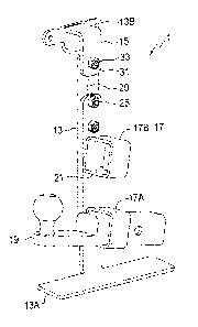
Un dispositif de rangement de barre d'attelage est adapté pour une installation dans une variété de boîtes de camion actuellement connue ayant un plancher rainuré où une plaque supérieure de chaque boîte sétend vers lintérieur dun rebord extérieur supérieur de la boîte et une cannelure sétend vers le bas dun rebord intérieur de la plaque supérieure, et où une distance de la cannelure à une rainure de cannelure est située sous la cannelure varie. Une patte de fixation de longueur réglable est configurée à une extrémité du bas de ladite patte en vue dengager la rainure de cannelure de sorte que le mouvement à gauche ou à droite de l'extrémité du bas de la patte de fixation est empêché et un dispositif de pince est fonctionnel pour pincer une extrémité supérieure de la patte de fixation à la cannelure. Les tubes récepteurs sont installés sur la patte de fixation et chaque tube récepteur est configuré pour recevoir une barre dattelage.


Abrégé anglais

A hitch drawbar storage apparatus is adapted for installation in a variety of presently known pick-up truck boxes with a grooved floor where a top plate of each box extends inward from a top outside edge of the box and a rib extends downward from an inner edge of the top plate, and where a distance from the rib to a rib groove located under the rib varies. An adjustable length mounting leg is configured at a bottom end thereof to engage the rib groove such that right and left movement of the bottom end of the mounting leg is prevented, and a clamp device is operative to clamp an upper end of the mounting leg to the rib. Receiver tubes are mounted on the mounting leg, and each receiver tube is configured to receive a drawbar.

Revendications

Note : Les revendications sont présentées dans la langue officielle dans laquelle elles ont été soumises.


CLAIMS
What is claimed is:
1. A hitch drawbar storage apparatus for installation in a variety of pick-
up truck
boxes, where a top plate of each box extends inward from a top outside edge of
the box and a rib extends downward from an inner edge of the top plate, where
a
floor of each box defines grooves extending from a front end of the box to a
back
end of the box, and where a distance from the rib to a rib groove located
under the
rib varies, the apparatus comprising:
an adjustable length mounting leg configured at a bottom end thereof to engage
the rib groove such that right and left movement of the bottom end of the
mounting leg is substantially prevented;
a clamp device operative to clamp an upper end of the mounting leg to the rib;
upper and lower receiver tubes mounted on the mounting leg, each receiver tube
configured to receive a drawbar.
2. The apparatus of claim 1 wherein the upper and lower receiver tubes
slope
downward from input ends thereof where the drawbar is inserted, to opposite
ends
thereof.
3. The apparatus of claim 2 wherein the input ends of the receiver tubes
face
rearward when the mounting plate is installed on a left side of the box.
4. The apparatus of any one of claims 1 - 3 wherein the mounting leg
comprises an
upper leg and a lower leg, and wherein the upper and lower legs are fixed to
each
other at a selected relative vertical position by a bolt extending through a
bolt hole
7

defined by one of the upper and lower legs and then through a vertical slot
defined by the other of the upper and lower legs.
5. The apparatus of claim 4 the upper and lower receiver tubes are mounted
on the
one of the upper and lower legs that defines the bolt hole.
6. The apparatus of any one of claims 4 and 5 wherein the upper leg defines
the
vertical slot, the upper and lower receiver tubes are mounted on the lower
leg, and
the lower leg defines the bolt hole above the upper receiver tube.
7. The apparatus of claim 6 wherein the clamp device is fastened to the
upper leg by
a clamp bolt extending through an upper portion of the vertical slot.
8. The apparatus of claim 7 wherein the upper end of the mounting leg is
configured
to extend upward on one side of the rib and wherein the clamping device bears
against a side of the rib opposite the upper end of the mounting leg.
9. The apparatus of any one of claims 1 ¨ 8 wherein the bottom end of the
mounting
leg comprises a base plate configured to slide down into the rib groove with
right
and left side edges of the base plate in sliding relationship to corresponding
right
and left sides of the rib groove.
10. The apparatus of claim 9 wherein the base plate slopes laterally such
that one of
the right and left side edges thereof is lower than the other and bears
against a
bottom corner of the rib groove.
8

Description

Note : Les descriptions sont présentées dans la langue officielle dans laquelle elles ont été soumises.


CA 02888267 2015-04-15
HITCH DRAWBAR STORAGE APPARATUS
This invention is in the field of hitches for connecting a trailer or like
towed vehicle to a
towing vehicle, and in particular an apparatus for storing hitch tubes.
BACKGROUND
Connecting hitch mechanisms for trailers take a variety of forms, such as
clevis and
tongue mechanisms, ball and socket mechanisms, pintle hook and ring
mechanisms, and
the like. In order to accommodate the different types of mechanisms it has
become
common to mount a tube bracket to the frame of the towing vehicle. A receiver
tube is
fixed to the tube bracket and defines a rectangular socket and allows an
operator to insert
and secure different rearward extending hitch drawbars that correspond to a
variety of
trailer hitches, thus facilitating towing a variety of trailers. The hitch
drawbar can also be
readily removed when not on use reducing the risk that a person will walk or
drive into
the drawbar.
Because these drawbars present somewhat of a hazard, in many jurisdictions it
is illegal
to leave the hitch drawbar in the socket on the towing vehicle, and so it is
necessary to
remove the drawbar and store it until the next time it is needed. Also it is
common to
have two different drawbars to accommodate two different trailers. Placing the
drawbar
loose in the truck box is inconvenient as they slide around the box and can
interfere with
loading the box. They can also be quite heavy and so present a hazard when the
truck
stops, starts, or turns suddenly sending the drawbar across the floor of the
box.
United States Patent Number 8,893,939 to Brass discloses a receiver tube
mounted on a
trailer where the drawbar is removed from the towing vehicle and stored with
the trailer.
1

CA 02888267 2015-04-15
This kind of storage is suitable where the towing vehicle is used to pull only
a single
trailer.
United States Patent Numbers 7,815,211 to Witchey, 6,527,292 to Adair, and
6,866,285
to Stamp disclose storage for a drawbar on the tube bracket, where the drawbar
extends
laterally in a storage position and rearward when in an operating position.
United States
Patent Number 8,231,035 to Michael discloses a receiver tube mounted to the
inside of a
truck box to store a drawbar.
For storage on the towing vehicle of two drawbars United States Patent Number
5,476,279 to Klemetsen discloses a laterally oriented receiver bracket which
defines
openings in each end thereof to store a drawbar extending laterally in each
end. United
States Published Patent Application Number 20080264991 of Foster discloses a
pair of
receiver tubes mounted in a tray that is bolted to holes drilled in the floor
of a truck box.
Light trucks or pick-up trucks, such as the Ford lm F150, Chevrolet
SilveradoTM, Dodge
Ram', and so forth, are commonly used for towing trailers. The boxes on these
pick-up
trucks are similar in that the steel floor of the boxes define grooves along
their length
from front to back, there is a rib extending down from the top inside edge of
the box, and
wheel wells extend up from the floor on each side of the box. The tray of
Foster is bolted
to the floor of such a pick-up truck near one side of the box just behind the
wheel well
where it is convenient to access the drawbars stored therein.
SUMMARY OF THE INVENTION
The present disclosure provides a drawbar storage apparatus that overcomes
problems in
the prior art.
2

CA 02888267 2015-04-15
In a first embodiment the present disclosure provides a hitch drawbar storage
apparatus
for installation in a variety of pick-up truck boxes, where a top plate of
each box extends
inward from a top outside edge of the box and a rib extends downward from an
inner
edge of the top plate, where a floor of each box defines grooves extending
from a front
end of the box to a back end of the box, and where a distance from the rib to
a rib groove
located under the rib varies. The apparatus comprises an adjustable length
mounting leg
configured at a bottom end thereof to engage the rib groove such that right
and left
movement of the bottom end of the mounting leg is substantially prevented, and
a clamp
device operative to clamp an upper end of the mounting leg to the rib. Upper
and lower
receiver tubes are mounted on the mounting leg, and each receiver tube is
configured to
receive a drawbar.
The presently disclosed hitch drawbar storage apparatus can be quickly
installed in the
boxes presently found on a wide variety of brands of pick-up truck without
drilling holes
or otherwise altering the box itself, and provides convenient storage for at
least two
drawbars.
DESCRIPTION OF THE DRAWINGS
While the invention is claimed in the concluding portions hereof, preferred
embodiments
are provided in the accompanying detailed description which may be best
understood in
conjunction with the accompanying diagrams where like parts in each of the
several
diagrams are labeled with like numbers, and where:
Fig. 1 is a schematic perspective view of an embodiment of the hitch drawbar
storage
apparatus of the present disclosure installed in a typical pick-up truck box;
3

CA 02888267 2015-04-15
Fig. 2 is a is a perspective front assembled view of the embodiment of Fig. 1
with a
hitch drawbar installed in the lower receiver tube;
Fig. 3 is a perspective front exploded view of the embodiment of Fig. 1;
Fig. 4 is a is a perspective rear assembled view of the embodiment of Fig. 1;
Fig. 5 is a schematic rear view of the embodiment of Fig. 1 installed in a
typical pick-
up truck box.
DETAILED DESCRIPTION OF THE ILLUSTRATED EMBODIMENTS
Figs. 1 - 4 illustrate an embodiment of a hitch drawbar storage apparatus 1 of
the present
disclosure for installation in a variety of pick-up truck boxes. A large
proportion of pick-
up truck boxes have certain common features which the present apparatus 1
utilizes to
allow installation of the apparatus 1. In a typical pick-up truck box 3 a top
plate 5 of the
box extends inward from a top outside edge of the box 3 and a rib 7 extends
downward
from an inner edge of the top plate 5. Similarly the floor 9 of a typical box
3 defines
grooves 11 extending from a front end of the box 3 to a back end thereof.
However in
these typical pick-up truck boxes 3 the distance D from the rib 7 to a rib
groove 11R
located under the rib 7 varies from about 16 inches to 20 inches,
The apparatus 1 thus comprises an adjustable length mounting leg 13 configured
at a
bottom end 13A thereof to engage the rib groove 11A such that right and left
movement
of the bottom end 13A of the mounting leg 13 is substantially prevented, and a
clamp
device 15 is operative to clamp an upper end 13B of the mounting leg 13 to the
rib 7.
Lower and upper receiver tubes 17A, 17B are mounted on the mounting leg 13 and
each
receiver tube 17 is configured to receive a drawbar 19.
4

CA 02888267 2015-04-15
The upper and lower receiver tubes 17 slope downward from input ends 21
thereof where
the drawbar 19 is inserted, to the opposite ends thereof, so that the drawbars
19 are held
in place in the receiver tubes 17 by gravity. Pins may also be placed in the
mounting
holes thereof if desired as well. For convenience, the input ends 21 of the
receiver tubes
17 face rearward when the mounting plate 13 is installed on the left driver's
side of the
box 3 as seen in Fig. 1.
The illustrated mounting leg 13 comprises a lower leg 23A and an upper leg
23B, and the
upper and lower legs 23 are fixed to each other at a selected relative
vertical position by
bolts 25 extending through bolt holes 27 defined by the lower leg 23A and then
through a
vertical slot 29 defined by the upper leg 23B. The receiver tubes 17 are
mounted on the
lower legs under the bolt holes 27. Conveniently the bolts 25 are carriage
bolts with a
square head that engages the sides of the slot 29 to facilitate tightening
nuts 31 onto the
bolts 25.
The clamp device 15 is fastened to the upper leg 23B by a clamp bolt 33
extending
through an upper portion of the vertical slot 29. As schematically illustrated
in Fig. 5, the
upper end of 13B of the mounting leg 13 on upper leg 23B extends upward on a
rear side
of the rib 7 and the clamping device 15 bears against the front side of the
rib 7 opposite
the upper end 13B of the mounting leg 13. It is contemplated that the upper
end of 13B
of the mounting leg 13 could also extends upward on the front side of the rib
7 and the
clamping device 15 bear against the rear side of the rib 7.
The bottom end 13A of the mounting leg 13 comprises a base plate 35 configured
to slide
down into the rib groove 11R with right and left side edges of the base plate
13 in sliding
relationship to corresponding right and left sides of the rib groove 11R. The
base plate
slopes laterally such that the right side edge 35R thereof is lower than the
left side
edge 35L and bears against a bottom corner of the rib groove 11R. It is
contemplated that
5

CA 02888267 2015-04-15
this configuration will better resist lateral movement of the bottom end 13A
of the
mounting leg 13.
The presently disclosed hitch drawbar storage apparatus 1 can be readily
installed in the
boxes presently found on a wide variety of brands of pick-up truck without
drilling holes
or otherwise altering the box itself, and provides convenient storage for at
least two
drawbars 19.
The foregoing is considered as illustrative only of the principles of the
invention.
Further, since numerous changes and modifications will readily occur to those
skilled in
=
the art, it is not desired to limit the invention to the exact construction
and operation
shown and described, and accordingly, all such suitable changes or
modifications in
structure or operation which may be resorted to are intended to fall within
the scope of
the claimed invention.
6

Dessin représentatif
Une figure unique qui représente un dessin illustrant l'invention.
États administratifs

2024-08-01 : Dans le cadre de la transition vers les Brevets de nouvelle génération (BNG), la base de données sur les brevets canadiens (BDBC) contient désormais un Historique d'événement plus détaillé, qui reproduit le Journal des événements de notre nouvelle solution interne.

Veuillez noter que les événements débutant par « Inactive : » se réfèrent à des événements qui ne sont plus utilisés dans notre nouvelle solution interne.

Pour une meilleure compréhension de l'état de la demande ou brevet qui figure sur cette page, la rubrique Mise en garde , et les descriptions de Brevet , Historique d'événement , Taxes périodiques et Historique des paiements devraient être consultées.

Historique d'événement

Description Date
Demande visant la révocation de la nomination d'un agent 2024-06-05
Demande visant la nomination d'un agent 2024-06-05
Exigences relatives à la nomination d'un agent - jugée conforme 2024-06-03
Exigences relatives à la révocation de la nomination d'un agent - jugée conforme 2024-06-03
Demande visant la révocation de la nomination d'un agent 2023-12-21
Exigences relatives à la révocation de la nomination d'un agent - jugée conforme 2023-12-21
Exigences relatives à la nomination d'un agent - jugée conforme 2023-12-21
Demande visant la nomination d'un agent 2023-12-21
Requête visant le maintien en état reçue 2023-01-03
Requête visant le maintien en état reçue 2022-01-19
Requête visant le maintien en état reçue 2021-01-19
Requête visant le maintien en état reçue 2020-01-17
Représentant commun nommé 2019-10-30
Requête visant le maintien en état reçue 2019-01-17
Requête visant le maintien en état reçue 2018-01-17
Accordé par délivrance 2017-04-11
Inactive : Page couverture publiée 2017-04-10
Requête visant le maintien en état reçue 2017-03-07
Préoctroi 2017-02-24
Inactive : Taxe finale reçue 2017-02-24
Un avis d'acceptation est envoyé 2016-10-31
Lettre envoyée 2016-10-31
Un avis d'acceptation est envoyé 2016-10-31
Inactive : Page couverture publiée 2016-10-26
Inactive : Approuvée aux fins d'acceptation (AFA) 2016-10-25
Inactive : QS réussi 2016-10-25
Demande publiée (accessible au public) 2016-10-16
Exigences relatives à la révocation de la nomination d'un agent - jugée conforme 2016-06-08
Exigences relatives à la nomination d'un agent - jugée conforme 2016-06-08
Inactive : Lettre officielle 2016-06-08
Modification reçue - modification volontaire 2016-06-07
Demande visant la révocation de la nomination d'un agent 2016-05-18
Demande visant la nomination d'un agent 2016-05-18
Inactive : Dem. de l'examinateur par.30(2) Règles 2016-03-07
Inactive : Rapport - Aucun CQ 2016-03-06
Inactive : Certificat de dépôt - RE (bilingue) 2015-05-11
Exigences de dépôt - jugé conforme 2015-05-11
Lettre envoyée 2015-05-11
Inactive : CIB attribuée 2015-04-29
Inactive : CIB en 1re position 2015-04-29
Inactive : CIB attribuée 2015-04-29
Demande reçue - nationale ordinaire 2015-04-23
Inactive : CQ images - Numérisation 2015-04-16
Exigences pour une requête d'examen - jugée conforme 2015-04-16
Toutes les exigences pour l'examen - jugée conforme 2015-04-16
Déclaration du statut de petite entité jugée conforme 2015-04-16
Inactive : Pré-classement 2015-04-16

Historique d'abandonnement

Il n'y a pas d'historique d'abandonnement

Taxes périodiques

Le dernier paiement a été reçu le 2017-03-07

Avis : Si le paiement en totalité n'a pas été reçu au plus tard à la date indiquée, une taxe supplémentaire peut être imposée, soit une des taxes suivantes :

  • taxe de rétablissement ;
  • taxe pour paiement en souffrance ; ou
  • taxe additionnelle pour le renversement d'une péremption réputée.

Veuillez vous référer à la page web des taxes sur les brevets de l'OPIC pour voir tous les montants actuels des taxes.

Historique des taxes

Type de taxes Anniversaire Échéance Date payée
Requête d'examen - petite 2015-04-16
Taxe pour le dépôt - petite 2015-04-16
Taxe finale - petite 2017-02-24
TM (demande, 2e anniv.) - petite 02 2017-04-18 2017-03-07
TM (brevet, 3e anniv.) - petite 2018-04-16 2018-01-17
TM (brevet, 4e anniv.) - petite 2019-04-16 2019-01-17
TM (brevet, 5e anniv.) - petite 2020-04-16 2020-01-17
TM (brevet, 6e anniv.) - petite 2021-04-16 2021-01-19
TM (brevet, 7e anniv.) - petite 2022-04-19 2022-01-19
TM (brevet, 8e anniv.) - petite 2023-04-17 2023-01-03
TM (brevet, 9e anniv.) - petite 2024-04-16 2024-02-26
Titulaires au dossier

Les titulaires actuels et antérieures au dossier sont affichés en ordre alphabétique.

Titulaires actuels au dossier
POWER PIN INC.
Titulaires antérieures au dossier
BRIAN R. OLSON
Les propriétaires antérieurs qui ne figurent pas dans la liste des « Propriétaires au dossier » apparaîtront dans d'autres documents au dossier.
Documents

Pour visionner les fichiers sélectionnés, entrer le code reCAPTCHA :


Pour visualiser une image, cliquer sur un lien dans la colonne description du document. Pour télécharger l'image (les images), cliquer l'une ou plusieurs cases à cocher dans la première colonne et ensuite cliquer sur le bouton "Télécharger sélection en format PDF (archive Zip)" ou le bouton "Télécharger sélection (en un fichier PDF fusionné)".

Liste des documents de brevet publiés et non publiés sur la BDBC .

Si vous avez des difficultés à accéder au contenu, veuillez communiquer avec le Centre de services à la clientèle au 1-866-997-1936, ou envoyer un courriel au Centre de service à la clientèle de l'OPIC.


Description du
Document 
Date
(aaaa-mm-jj) 
Nombre de pages   Taille de l'image (Ko) 
Abrégé 2015-04-15 1 18
Description 2015-04-15 6 216
Dessins 2015-04-15 3 51
Revendications 2015-04-15 2 63
Dessins 2016-06-07 3 48
Dessin représentatif 2016-09-20 1 7
Page couverture 2016-10-26 1 36
Page couverture 2017-03-08 2 39
Courtoisie - Lettre du bureau 2024-07-03 3 288
Changement d'agent - multiples 2024-06-05 4 156
Courtoisie - Lettre du bureau 2024-01-17 2 164
Courtoisie - Lettre du bureau 2024-01-17 1 189
Paiement de taxe périodique 2024-02-26 1 24
Accusé de réception de la requête d'examen 2015-05-11 1 174
Certificat de dépôt 2015-05-11 1 204
Avis du commissaire - Demande jugée acceptable 2016-10-31 1 162
Rappel de taxe de maintien due 2016-12-19 1 111
Demande de l'examinateur 2016-03-07 3 211
Correspondance 2016-05-18 4 123
Courtoisie - Lettre du bureau 2016-06-08 2 71
Modification / réponse à un rapport 2016-06-07 6 174
Taxe finale 2017-02-24 1 43
Paiement de taxe périodique 2017-03-07 2 60
Paiement de taxe périodique 2018-01-17 2 51
Paiement de taxe périodique 2019-01-17 3 101
Paiement de taxe périodique 2020-01-17 3 97
Paiement de taxe périodique 2021-01-19 3 85
Paiement de taxe périodique 2022-01-19 2 50
Paiement de taxe périodique 2023-01-03 3 90