Note : Les descriptions sont présentées dans la langue officielle dans laquelle elles ont été soumises.
CA 02889245 2015-04-21
TALAR DOME FIXATION STEM
BACKGROUND
[00011 An ankle joint may become severely damaged and painful due to
arthritis, prior
ankle surgery, bone fracture, osteoarthritis, and/or one or more additional
conditions. Options
for treating the injured ankle have included anti-inflammatory and pain
medications, braces,
physical therapy, joint arthrodesis, and total ankle replacement.
[00021 Total ankle replacement generally comprises two or more components
¨ one
portion coupled to the tibia and one portion coupled to the talus. The
components comprise
articulation surfaces sized and configured to mimic the range of motion of the
ankle joint. For
example, the talar portion may comprise a component sized and configured to
mimic the talar
dome and the tibial portion may comprise an articulation surface configured to
mimic
articulation of the tibia.
[00031 Installation of the total ankle replacement may comprise forming
one or more
holes, slots or cuts in a bone. For example, a hole may be drilled through the
talus and into the
tibia to create a channel for inserting a tibial stem. As another example,
slots can be reamed with
an end mill or punch having a guide. In some installations, additional bone is
removed from the
talus to make space for a talar stem extending from the talar portion.
SUMMARY
[00041 In some embodiments, a bone implant is disclosed. The bone implant
generally
comprises a body and a stem. The body comprises a bone contact surface and an
articulation
surface. The stem extends longitudinally from the bone contact surface. At
least one fin is
coupled to the stem and the body to provide anterior/posterior stability,
rotational stability,
mediaUlateral stability, and axial resistance.
100051 In some embodiments, a bone implant is disclosed. The bone implant
generally
comprises a body and a stem. The body comprises a bone contact surface and an
articulation
surface. The stem extends longitudinally from the bone contact surface. A
spline is formed
about the stem. The spline is sized and configured to provide
anterior/posterior stability,
rotational stability, medial/lateral stability, and axial resistance.
DM2,5076728.1
CA 02889245 2015-04-21
Patent
E3383-00584
[0006] In some embodiments, a bone implant is disclosed. The bone implant
generally
comprises a body and a stem. The body comprises a bone contact surface and an
articulation
surface. The stem extends longitudinally from the bone contact surface and
comprises a
triangular stem having a first leg, a second leg, and a third leg. At least
one of the first leg, the
second leg, the third leg, defines a plurality of serrations foi ined
thereon. The triangular stern
and the plurality of serrations provide anterior/posterior stability,
rotational stability,
medial/lateral stability, and axial resistance.
BRIEF DESCRIPTION OF THE FIGURES
[0001] The features and advantages of the present invention will be more
fully disclosed
in, or rendered obvious by the following detailed description of the preferred
embodiments,
which are to be considered together with the accompanying drawings wherein
like numbers refer
to like parts and further wherein:
[0002] FIG. I illustrates an anatomic view of an ankle joint.
[0003] FIG. 2 illustrates one embodiment of an ankle joint having a total
ankle
replacement system therein.
100041 FIG. 3 illustrates a side view of one embodiment of a talar dome
comprising a
stem having a plurality of fins.
[0005] FIG. 4 illustrates a front view of the talar dome of FIG. 3.
[0006] FIG. 5 illustrates a bottom view of the talar dome of FIG. 3.
[0007] FIG. 6 illustrates a side view of one embodiment of a talar dome
comprising a
stem having a spline formed thereon.
[0008] FIG. 7 illustrates a bottom view of the talar dome of FIG. 6.
[0009] FIG. 8 illustrates a front view of the talar dome of FIG. 6.
[0010] FIG. 9 illustrates a side view of one embodiment of a talar dome
comprising a
triangular stem defining a plurality of serrated blades.
2
Dm2,5076722..i
CA 02889245 2015-04-21
Patent
E3383-00584
[00111 FIG. 10 illustrates an angled bottom view of the talar dome of
FIG. 9.
[00121 FIG. 11 illustrates a bottom view of the talar dome of FM. 9.
[00131 FIG. 12 illustrates a front view of the talar dome of FIG. 9.
DETAILED DESCRIPTION
[00011 The description of the exemplary embodiments is intended to be
read in
connection with the accompanying drawings, which are to be considered part of
the entire
written description. In the description, relative terms such as "lower," -
upper," "horizontal,"
"vertical," "proximal," "distal," "above," "below," "up," "down," "top" and
"bottom," as well as
derivatives thereof (e.g., "horizontally," "downwardly," "upwardly," etc.)
should be construed to
refer to the orientation as then described or as shown in the drawing under
discussion. These
relative terms are for convenience of description and do not require that the
apparatus be
constructed or operated in a particular orientation. Terms concerning
attachments, coupling and
the like, such as -connected" and "interconnected," refer to a relationship
wherein structures are
secured or attached to one another either directly or indirectly through
intervening structures, as
well as both movable or rigid attachments or relationships, unless expressly
described otherwise.
[00021 The present disclosure generally provides a bone implant for use
with a joint
replacement system. The bone implant comprises a body having a bone contact
surface and an
articulation surface. A stem extends longitudinally from the bone contact
surface. The stem
comprises one or more features configured to provide rotational,
translational, and pull-out
resistance to the implant with respect to a bone. The stem and the one or more
features are
configured to interface with a hole formed in a bone, such as, for example, a
talus.
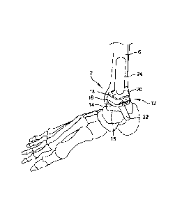
[00031 FIG. I illustrates an anatomic view of an ankle joint 2. The ankle
joint 2
comprises a talus 4 in contact with a tibia 6 and a fibula 8. A calcaneus 10
is located adjacent to
the talus 4. In total ankle replacements, the talus 4 and the tibia 6 may be
resected, or cut, to
allow insertion of a talar implant and a tibial implant. FIG. 2 illustrates
the ankle joint 2 of FIG.
1 having a total ankle replacement system 12 inserted therein.
3
DM2\5076728.1
CA 02889245 2015-04-21
Patent
E3383-00584
[0004] The total ankle replacement system 12 comprises a talar platform
14 and a tibial
platform 18. The talar platform 14 comprises a body 15 defining a talar
articulation surface 16
(or talar dome). A stem 22 extends into the talus 4 to anchor the talar
platform 14 to the talus 4.
The tibial platform 18 is sized and configured for installation into the tibia
6. The tibial platform
18 comprises a body having an articulation surface 20 and a tibial stem 24
extending into the
tibia 6 to anchor the tibial platform 18. The talar joint surface 16 and the
tibial joint surface 20
are mutually sized and configured to articulate. The joint surfaces 16, 20
replace the natural
ankle joint surfaces, which are removed, to restore a range of motion and a
height that mimics
the natural joint. One or more holes may be formed in the tibia and/or the
talus prior to and
during insertion of the tibial implant 18 or the talar implant 12. For
example, in some
embodiments, a hole is drilled starting in the bottom of the talus, extending
through the talus and
into the tibia. The hole may comprise, for example, a 6mm hole configured to
receive the stem
24 of the tibial platform 18.
[0005] The joint surfaces 16, 20 may be made of various materials, such
as, for example,
polyethylene, high molecular weight polyethylene (HMWPE), rubber, titanium,
titanium alloys,
chrome cobalt, surgical steel, and/or any other suitable metal, ceramic,
sintered glass, artificial
bone, and/or any combination thereof. In some embodiments, the joint surfaces
16, 20 may
comprise a coated surface. For example, in some embodiments, the joint
surfaces 16, 20 may be
plasma sprayed with a porous material, such as, for example, a biofoam
material. The joint
surfaces 16, 20 may comprise different materials. For example, the tibial
joint surface 20 may
comprise a plastic or other non-metallic material and the talar joint surface
16 may comprise a
metal surface. Those skilled in the art will recognize that any suitable
combination of materials
may be used.
[0006] FIG. 3 is a side view of one embodiment of an implant 102
comprising a stem 104
having one or more fins 106. The implant 102 comprises a body an articulation
surface 106 and
a bone contact surface 108. The joint articulation surface 106 is sized and
configured to allow
articulation of a bone and/or implant in contact with the articulation surface
106. For example,
in some embodiments, the implant 102 comprises a talar implant. The
articulation surface 106 is
sized and configured to allow articulation of a tibia and/or tibial implant in
contact with the
4
DM2 \ 5076728.1
CA 02889245 2015-04-21
Patent
E3383-00584
implant 102 after installation. In other embodiments, the articulation surface
106 may be sized
and configured to allow articulation of additional and/or alternative bones
and/or implants.
[0007] The body 104 further comprises a bone contact surface 108 located
opposite from
the articulation surface 106. The bone contact surface 108 is configured to
interface with a bone
surface prepared during surgery. For example, in some embodiments, the bone
contact surface
108 is configured to interface with a resected bone surface, such as a
resected talus, to couple the
implant 102 to the bone. In some embodiments, the bone contact surface 108
comprises a
generally planar surface. In other embodiments, the bone contact surface 108
comprises a
concave surface. In some embodiments, only a portion of the bone contact
surface 108, such as,
for example, an outer perimeter, interfaces with the bone surface prepared
during surgery. The
bone contact surface 108 may comprise a surface lip located at the edge of the
implant 102 sized
and configured to maintain the implant 102 in a proper location and/or
alignment with respect to
the bone. In some embodiments, the bone contact surface 108 comprises multiple
bone contact
points/surfaces.
[0008] A stem 110 extends longitudinally at an angle from the bone
contact surface 108.
The stem 110 is sized and configured to be inserted into a hole formed in the
bone during
surgery. The stem 110 extends a predetermined distance from the bone contact
surface 108. In
some embodiments, the stem 110 extends a predetermined distance that is less
than, equal to, or
greater than a thickness of the body 104. For example, the stem 110 may extend
a distance equal
to the distance between the articulation surface 106 and the bone contact
surface 108 of the body
104. The stem 110 may extend at any suitable angle from the bone contact
surface 108. For
example, in various embodiments, the stem 110 may extend at an angle of
between 0-180
degrees from the bone contact surface 108.
[0009] The stem 110 comprises one or more features configured to provide
rotational,
translational, and/or pull-out resistance to the stem 110. In the illustrated
embodiment, the stem
110 comprises one or more fins 112a, 112b. The fins 112a, 112b extend from the
bone contact
surface 108 and the stem 110. The fins 112a, 112b provide anterior/posterior
stability,
longitudinal stability, and medial/lateral stability to the implant 102 when
the implant 102 is
coupled to a bone. The fins 112a, 112b are inserted into channels formed in
the bone during
DNI2 s076728.1
CA 02889245 2015-04-21
Patent
E3383-00584
surgery. For example, in one embodiment, the fins 112a, 112b are inserted into
fin channels
formed in a talus during a talar resectioning procedure. The fins 112a, 112b
contact the side
walls of the channels and maintain the implant 102 in a predetermined position
and alignment
with respect to the bone. FIG. 4 illustrates a front view of the implant 102.
In some
embodiments, the body 104 of the implant 102 defines one or more holes 114a,
114b sized and
configured to receive a handle therein (not shown) to allow manipulation of
the talar implant
during implantation.
[00101 In some embodiments, the implant 102 is coupled to the bone to
provide axial
resistance. For example, in one embodiment, the implant 102 is cemented to the
bone. The
implant may be cemented to the bone at the bone contact surface 108 and/or at
the stem 110. As
another example, in one embodiment, the implant 102 is press-fit into a hole
formed in the bone.
The hole is sized and configured to receive the stem 110 in a press-fit
engagement. The implant
102 may be coupled to the bone by any other suitable method and/or any
combination of
methods, such as, for example, being cemented and press-fit into engagement
with the bone.
[00111 FIG. 5 illustrates a bottom view of the implant 102. As shown in
FIG. 4, the stem
110 and the fins 112a, 112b extend longitudinally from the bone contact
surface 108. Although
two fins 112a, 112b are illustrated, it will be recognized that the implant
102 may comprise any
number of one or more fins. The fins 112a, 122b comprise semi-circular
sections extending
from the bone contact surface 108 to the stem 110. Although the fins 112a,
112b are illustrates
as semi-circular, it will be recognized that the fins may comprise any
suitable shape such, as for
example, rectangular, triangular, and/or any other suitable shape.
[00121 FIG. 6 illustrates a side view of one embodiment of an implant 202
comprising a
stem 210 having a spline 218 formed thereon. FIG. 7 illustrates a bottom view
of the implant
202. The implant 202 is similar to the implant 102 described with reference of
FIGS. 3-5 above.
The implant 202 comprises an implant body 204. The implant body 204 defines an
articulation
surface 206 and a bone contact surface 208. A stem 210 extends longitudinally
from the bone
contact surface 208. The stem 210 comprise one or more features configured to
provide
rotational, translational, and/or pull-out resistance to the implant 202 with
respect to a bone.
6
nNi2,506728.i
CA 02889245 2015-04-21
Patent
E3383-00584
[0013] In the illustrated embodiment, the one or more features comprise a
spline 218.
The spline 218 comprises a plurality of teeth 220a-220e. The plurality of
teeth 220a-220e are
configured to provide anterior/posterior stability, rotational stability, and
medial/lateral stability.
In some embodiments, the plurality of teeth 220a-220e are configured to
interface with a
plurality of grooves formed in a hole in the bone. The teeth 220a-220e
interface with the
grooves formed in the hole to prevent movement and rotation of the implant 202
with respect to
the bone.
100141 FIG. 8 illustrates a front view of the implant 202. The body 204
of the implant
202 may define one or more holes 214a, 214b sized and configured to couple the
implant 202 to
one or more additional implants. For example, in some embodiments, the implant
202 comprises
a talar dome platform configured to couple to a talus and to receive a talar
dome thereon. The
plurality of holes 214a, 214b are configured to receive one or more mating
features of the talar
dome therein to mate the talar dome to the implant 202. In other embodiments,
the plurality of
holes 2I4a, 214b may be coupled to an adjacent implant, such as, for example,
a tibial implant,
to maintain the implant 202 and the adjacent implant in a predetermined
spacing/alignment.
[0015] FIG. 9 illustrates a side view of one embodiment of an implant 302
comprising a
triangular stem 310 having a plurality of serrations 332 formed thereon. FIG.
10 illustrates a
bottom view of the implant 302. The implant 302 is similar to the implant 102
described with
reference of FIGS. 3-5 above. The implant 302 comprises an implant body 304.
The implant
body 304 defines an articulation surface 306 and a bone contact surface 308. A
stem 310
extends longitudinally from the bone contact surface 308. The stem 310
comprise one or more
features configured to provide rotational, translational, and/or pull-out
resistance to the implant
302 with respect to a bone.
[0016] The triangular stem 310 comprises a first leg 330a, a second leg
330b, and a third
leg 330c. In some embodiments, the plurality of legs 330a-330c are equally
spaced about a
circumference of the stem 310. Each of the plurality of legs 330a-330c
comprises a plurality of
serrations 332 formed on an outer edge of the leg 330a-330c. The stem 310 may
be inserted into
a hole formed in a bone, such as, for example, a talus. The hole may comprise
any suitable
shape for receiving the stem 310, such as, for example, a triangular, square,
round, or other
7
DM2\5076728.1
CA 02889245 2015-04-21
Patent
E3383-00584
cross-sectional shape. The plurality of legs 330a-330c prevent
anterior/posterior motion,
rotational motion, and/or medial/lateral motion. The plurality of serrations
332 are configured to
provide pull-out resistance to the stem 310.
[0017] FIG. 10 is an angled bottom view of the implant 302. The angled
bottom view
illustrates the serrated portions 332 of each of the legs 330a-330c. The legs
330a-330c each
extend longitudinally from the bone contact surface 308. In the illustrated
embodiment, the legs
330a-330c are equally spaced about a circumference defined by the stem 310. In
other
embodiments, the each of the legs 330a-330c may be separated from each of the
other legs by
unequal distances and/or angles. For example, the first leg 330a may be
separated from the
second leg by a first angle and from the third leg by a second angle. The
second and third legs
may be separated by a third angle.
[00181 FIG. 11 illustrates a bottom view of the implant 302. The bottom-
view illustrates
the triangular, or christmas-tree shape, of the stem 310. The shape of the
stem 310 provides
anterior/posterior stability, rotational stability, and medial/lateral
stability. In some
embodiments, the edges of the legs 330a-330c are sharp to allow the edges 330a-
330c to bite or
dig into a bone to provide further stability. The serrations 332 may also be
sharp in order to
provide additional stability and pull-out resistance.
[0019] FIG. 12 illustrates a front view of the implant 302. The body 304
of the implant
302 may define one or more holes 314a, 314h sized and configured to couple the
implant 302 to
one or more additional implants. For example, in some embodiments, the implant
302 comprises
a talar dome platfot in configured to couple to a talus and to receive a
talar dome thereon. The
plurality of holes 314a, 314b are configured to receive one or more mating
features of the talar
dome therein to mate the talar dome to the implant 302. In other embodiments,
the plurality of
holes 314a, 314b may be coupled to an adjacent implant, such as, for example,
a tibial implant,
to maintain the implant 302 and the adjacent implant in a predetermined
spacing/alignment.
[0020] In various embodiments, an implant is disclosed. The implant a body
having a
bone contact surface and an articulation surface. A stem extends
longitudinally from the bone
contact surface. At least one fin is coupled to the stem and the body.
8
DM2 \ 5076728. I
CA 02889245 2015-04-21
Patent
E3383-00584
[0021] In some embodiments, the at least one fin is sized and configured to
be received
within a channel formed in a bone to prevent anterior/posterior movement,
rotational movement,
and medial/lateral movement.
[0022] In some embodiments, the at least one fin comprises a wedge shaped
fin.
[0023] In some embodiments, the wedge-shaped fin comprises a first flat
edge coupled to
the stem, a second flat edge coupled to the body, and an arcuate edge
extending from an end of
the first flat edge to an end of the second flat edge.
[0024] In some embodiments, the implant comprises a first fin located on a
first side of
the stem and a second fin located on a second side of the fin.
[0025] In some embodiments, the body defines at least one instrument hole
sized and
configured to receive an instrument for deploying the implant therein.
[0026] In some embodiments, the stem extends a predetermined distance from
the body,
and wherein the predetermined distance is less than a thickness of the body.
[0027] In some embodiments, the articulation surface is sized and
configured to mimic a
talar dome.
[0028] In various embodiments, an implant is disclosed. The implant
comprises a body
having a bone contact surface and an articulation surface. A stem extends
longitudinally from
the bone contact surface. A spline is formed about the stem.
[0029] In some embodiments, the spline is sized and configured to be
received within a
channel formed in a bone to prevent anterior/posterior movement, rotational
movement, and
medial/lateral movement.
[0030] In some embodiments, the spline comprises a plurality of equally
spaced teeth
disposed about a circumference of the stem.
[00311 In some embodiments, the body defines at least one instrument hole
sized and
configured to receive an instrument for deploying the implant therein.
9
DM2 5076728.1
CA 02889245 2015-04-21
Patent
E3383-00584
[00321 In some embodiments, the stem extends a predetermined distance
from the body,
and wherein the predetermined distance is less than a thickness of the body.
[0033] In some embodiments, the articulation surface is sized and
configured to mimic a
talar dome.
[0034] In various embodiments, an implant is disclosed. The implant
comprises a body
having a bone contact surface and an articulation surface. A triangular stem
having a first leg, a
second leg, and a third leg extends longitudinally from the body. At least one
of the first leg, the
second leg, or the third leg, defines a plurality of serrations formed
thereon.
[0035] In some embodiments, the triangular stem is sized and configured
to prevent
rotational movement, anterior/posterior movement, and medialllateral movement,
and wherein
the plurality of serrations provide pull-out resistance to the stem.
[0036] In some embodiments, each of the first leg, the second leg, and
the third leg
comprise a sharpened edge.
[00371 In some embodiments, the body defines at least one instrument hole
sized and
configured to receive an instrument for deploying the implant therein.
[0038] In some embodiments, the stem extends a predetermined distance
from the body,
and wherein the predetermined distance is less than a thickness of the body.
[0039] In some embodiments, the articulation surface is sized and
configured to mimic a
talar dome.
[0040] Although the subject matter has been described in terms of
exemplary
embodiments, it is not limited thereto. Rather, the appended claims should be
construed broadly,
to include other variants and embodiments, which may be made by those skilled
in the art.
DM2 5076728.1