Note : Les descriptions sont présentées dans la langue officielle dans laquelle elles ont été soumises.
CA 02889734 2015-04-27
- 1 -
Spray Head and Container Provided with The Same
TECHNICAL FIELD
[0001] The present invention relates to an ejection head that includes an
inner
passage to which a stem is fixed and that ejects a content drawn from the stem
to an
outside by displacing the stem upward and downward.
BACKGROUND
[0002] The present inventor has already proposed a known ejection head
including a pressing member that drives a pump located in a container and a
nozzle
tip that is embedded with an insert member and is fixed to the pressing
member,
wherein the content is ejected through an orifice provided in the nozzle tip
(Refer to
Patent Literature I, for example).
CITATION LIST
Patent Literature
[0003]
PTL 1: JP2011177627A
SUMMARY
[0004] However, the present inventor conducted further tests and studies
and has
realized that the proposed ejection head still has room for improvement.
[0005] An objective of the present invention is to provide an ejection head
that
is capable of producing stable ejection patterns.
[0006] One aspect of the present invention resides in an ejection head,
including: a pressing member that is fitted to a stem standing from a mouth
tubular
portion of a container body and that is formed with an introduction path to
which a
content medium is introduced; a nozzle tip that is fitted to a concavity
formed on a
side surface of the pressing member and that is formed with an ejection
orifice for
the content medium pumped from the introduction path; and an insert member
that
is located inside the nozzle tip and that forms a communication path allowing
the
introduction path formed in the pressing member to communicate with the
ejection
orifice formed in the nozzle tip. The insert member includes: a concave
portion
having an opening formed in a rear end of the insert member that faces to the
pressing member, thereby forming a filling space to be filled with the content
medium introduced from the introduction path; at least one through hole formed
on
a circumferential wall constituting the concave portion; and a long groove
that is
formed on the circumferential wall and that extends from the at least one
through
hole to the nozzle tip. The insert member has a front end facing to the nozzle
tip,
the front end having an outer circumferential edge formed as an annular
inclined
surface tapered toward a front end thereof, and the front end being formed
with a
bulging portion that protrudes forward of the inclined surface, the bulging
portion
being formed with a plurality of radial grooves and a cylindrical groove where
the
plurality of radial grooves joins, and at least one of the at least one
through hole is
located in a position that is circumferentially offset from the plurality of
radial
grooves.
[0007] Although the at least one through hole may of course include a
through
Your Ref.: S454
Our Ref.: P0123984-PCT
(1/14)
CA 02889734 2015-04-27
- 2 -
hole having a constant diameter, the at least one through hole may include a
slant
hole having a diameter that is increased in a direction from an inside to an
outside
of the insert member. Furthermore, the at least one through hole may be a
single
through hole that is located in a position that is circumferentially offset
from the
plurality of radial grooves.
[0008] The
introduction path may include an opening formed in any position,
for example, in an upper position. In this case, the opening allows the
introduction
path to communicate with the filling space.
[0009] Moreover,
according to the present invention, the concavity may be
provided with a plurality of bumps that form a plurality of radial grooves and
a
cylindrical groove where the plurality of radial grooves joins. By bringing
the insert
member into abutment with the plurality of bumps, a guiding path allowing the
introduction path to communicate with the communication path may be formed.
[0010] Another
aspect of the present invention resides in a pump container
including an ejection head. The pump container includes the ejection head and
a
container body including a pump having a stem to which the ejection head is
fitted.
[0011] According
to the present invention, the insert member is located inside
the nozzle tip to form the communication path communicating with the ejection
orifice, and the through hole, which is formed on the circumferential wall of
the
insert member, is located in the position that is circumferentially offset
from the
radial grooves, which is formed on the front end of the insert member. With
the
above configuration, the ejection patterns, which are defined by states,
angles, or
the like of spraying, are better stabilized compared with conventional
ejection
patterns.
BRIEF DESCRIPTION OF THE DRAWINGS
[0012]
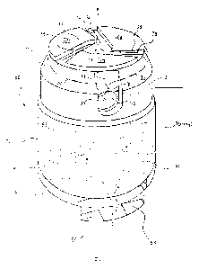
FIG. I is a side view taken along a partial section of a pump bottle container
including a spray nozzle according to one embodiment of the present invention.
FIG. 2 is an enlarged sectional view of the spray nozzle according to the one
embodiment.
FIG. 3 is an enlarged front view of a concave portion formed on a side surface
of a pressing member according to the one embodiment.
FIG. 4A is a front view of an insert member according to the one embodiment,
and FIG. 4B is a sectional view taken along a line A-A in FIG. 4A.
FIG. 5A is a side view of the insert member, and FIG. 5B is a perspective view
of the insert member.
FIG. 6 is a sectional view taken along a line B-B in FIG. 2 that is partially
virtual.
FIG. 7 is a schematic perspective view of a passage (a flow path) of a content
medium passing between a nozzle tip and the insert member according to the one
embodiment.
FIG. 8A is a schematic view of a state of spraying with use of the spray head
according to the one embodiment, and FIG. 8B is a view of a state of spraying
with
use of a conventional spray head.
FIG. 9A is a partial bottom view of an exemplary protrusion formed in an
upper end flange according to the one embodiment, and FIG. 9B is a sectional
view
Your Ref.: S454
Our Ref.: P0123984-PCT
(2/14)
CA 02889734 2015-04-27
- 3 -
taken along a line C-C in FIG. 9A.
FIG. 10A is a partial bottom view of another exemplary protrusion formed in
the upper end flange according to the one embodiment, and FIG. 10B is a
sectional
view taken along a line D-D in FIG. 10A.
FIG. 11A is a partial bottom view of yet another exemplary protrusion formed
in the upper end flange according to the one embodiment, and FIG. 11B is a
sectional view taken along a line E-E in FIG. 11A.
FIG. 12A is an enlarged sectional view of an exemplary protrusion formed on a
lower end surface of the pressing member according to the one embodiment, and
FIG. 12B is an enlarged sectional view of an area X in FIG. 12A.
FIG. 13A is an enlarged sectional view of another exemplary protrusion
formed on the lower end surface of the pressing member according to the one
embodiment, and FIG. 13B is an enlarged sectional view of an area Yin FIG.
13A.
DETAILED DESCRIPTION
[0013] One embodiment of a pump bottle container including a spray head of
the
present invention will be described in detail below with reference to the
drawings.
[0014] In FIG. 1, reference numeral 10 denotes the pump bottle container
including a spray head H according to the one embodiment of the present
invention.
Reference numeral 20 denotes a container body. The container body 20 is a
bottle-type container including a mouth tubular portion 21, a shoulder portion
22,
and a trunk portion 23 connecting to the mouth tubular portion 21 via the
shoulder
portion 22. An inside of the container body 20 is filled with a content medium
M.
[0015] To the container body 20, a pump unit P is fixed. The pump unit P
includes a first cylinder 31 that is located inside the mouth tubular portion
21. The
first cylinder 31 includes a small-diameter portion 31a and a large-diameter
portion
31b, and an ambient air introduction hole 31n formed between the small-
diameter
portion 31a and the large-diameter portion 31b. The large-diameter portion 31b
is
provided with an upper end flange 32. With the upper end flange 32 being
received
and rest on an upper end of the mouth tubular portion 21, the first cylinder
31 is
held inside the mouth tubular portion 21 in a hanging manner. The first
cylinder 31
also includes a fitting tube 33 that is connected to the upper end flange 32.
The
fitting tube 33 is fixed to the mouth tubular portion 21 by a fixing means C1.
As
illustrated in the figure, the fixing means may be a screw means. However,
according to the present invention, the fixing means CI is not limited to the
screw
means. There is also provided an annular seal member S to seal between the
mouth
tubular portion 21 and the upper end flange 32. From the upper end flange 32,
a
guiding tube 34 also stands.
[0016] The small-diameter portion 31a of the first cylinder 31 is formed,
on an
inner side thereof, with an annular concave groove 31c extending
circumferentially
about a pump axis line (hereinafter, called "axis line") 01. To the small-
diameter
portion 31a, an intake pipe 35, which communicates with the inside of the
container
body 20, is fixed. The content medium M drawn through the intake pipe 35 is
introduced to an inside of the first cylinder 31 via a check valve 36. Inside
the first
cylinder 31, a pump plunger 38 is elastically supported via a spring 37.
100171 The pump plunger 38 includes a plunger body 38a. The plunger body
38a
includes a first piston 38b and a second piston 38c. The first piston 38b and
the
Your Ref.: S454
Our Ref: P0123984-PCT
(3/14)
,
CA 02889734 2015-04-27
- 4 -
second piston 38c are integrally coupled via a plurality of ribs 38d that are
located
around the plunger body 38a at an interval. The first piston 38b, together
with the
small-diameter portion 31a of the first cylinder 31, forms a first pump
chamber RI.
The first pump chamber R1 has a pressure that is released when the first
piston 38b
reaches the annular concave groove 31c. An upper end opening of the first
cylinder
31 is sealed by a lower end tube 39a included in a second cylinder 39. The
lower
end tube 39a, upon reaching the small-diameter portion 31a of the first
cylinder 31,
allows the ambient air introduction hole 31n to communicate with the outside.
The
second cylinder 39 also includes an upper end tube 39b formed with an opening,
which is sealed by a cylinder cap 40. The cylinder cap 40, together with the
upper
end tube 39b of the second cylinder 39, defines space for accommodating the
second piston 38c. Between the second piston 38c and the cylinder cap 40, a
second
pump chamber R2 is also formed. The second pump chamber R2 communicates with
the first pump chamber R1 through a gap formed between adjacent ribs 38d
around
the pump plunger 38. Furthermore, in the cylinder cap 40, an upper end opening
A1
is formed for allowing the first pump chamber R1 and the second pump chamber
R2
to communicate with the outside. The upper end opening A1 may be opened and
closed by a tip portion 38a1 of the plunger body 38a. Accordingly, the tip
portion
38a1 serves as a check valve (a discharge valve).
[0018] Moreover, the cylinder cap 40 is provided with a stem 41
surrounding the
upper end opening Al. Inside the stem 41, a mesh ring 42 is disposed. As
illustrated
in FIG. 2, the mesh ring 42 is configured by a ring member 42a and a mesh
member
42b adhered to one end of the ring member 42a. The mesh ring 42 may be
disposed
in plurality inside the stem 41. The mesh ring 42 may also be omitted.
[0019] Reference numeral H denotes the spray head constituting the pump
unit P.
The spray head H includes a pressing member 50 that is to be operated by a
user.
The pressing member 50 has a cylindrical shape in appearance, with an upper
end
thereof being formed as a pressing surface 50f. The pressed member 50 is also
provided, in a lower end thereof, with an outer tubular portion 51a and an
inner
tubular portion 51b that are integrated. As illustrated in FIG. I, the outer
tubular
portion 51a includes a slip-off preventing portion 51c. The slip-off
preventing
portion 51c slides over a slip-off preventing portion 34c formed in the
guiding tube
34 to be fitted and then locked by the slip-off preventing portion 34c. Thus,
the
pressing member 50 is held by the guiding tube 34 in a manner such that the
pressing member 50 is prevented from slipping off. The inner tubular portion 5
1 b of
the pressing member 50 is also fitted and held inside the stem 41.
Furthermore, the
pressing body 50 is formed, inside thereof, with an introduction path 1 into
which
the content medium M pumped through the mesh ring 42 is introduced. The
introduction path 1 includes a vertical flow path la, which includes an
opening on
an inner side of a lower end of the inner tubular portion 51b and which
extends
along the axis line 01, and a front-rear (horizontal) flow path lb, which
extends
from the flow path la toward a side surface of the pressing member 50. As
illustrated in FIG. 2, the front-rear flow path lb communicates with a
concavity 50n
formed on the side surface of the pressing member 50.
[0020] FIG. 3 is a front view of the concavity 50n. The concavity 50n is
formed
in a cylindrical shape. The concavity 50n includes a flat partition wall 53
that is
integrally provided with a plurality of bumps 55. The bumps 55 each extend
from an
Your Ref.: S454
Our Ref.: P0123984-PCT
(4/14)
- 5 -
inner circumferential surface 54 of the concavity 50n toward a center 02 of
the
concavity 50n. The front-rear flow path lb has an opening A2 formed in an
upper
position of the concavity 50n that is near the pressing surface 50f. On both
sides of
the opening A?, stepped surfaces 56 connecting to the partition wall 53 are
also
formed.
[0021] Next, with reference to FIG. 2, reference numeral 60 denotes a
nozzle tip
that is fixed to the concavity 50n. The nozzle tip 60 includes a partition
wall 61 that
is provided with an ejection orifice 60a. The nozzle tip 6() also includes a
circumferential wall 62 connected to the partition wall 61, thus forming a
concavity
inside the nozzle tip 60. The circumferential wall 62 of the nozzle tip 60 is
fixed to
the concavity 50n. In detail, the circumferential wall 62 of the nozzle tip 60
is fixed
to the inner circumferential surface 54 of the concavity 50n by a fixing means
As illustrated in the figure, the fixing means C, may be configured by an
annular
groove and an annular projection. The circumferential wall 62 is also provided
with
an annular sealing portion 63 that seals the inner circumferential surface 54
of the
concavity 50n. The inner circumferential surface 54 of the concavity 50n is
sealed
by the nozzle tip 60. With the above configuration, the opening of the
concavity 50n
is tightly closed by the partition wall 61 of the nozzle tip.
[0022] Reference numeral 70 denotes an insert member that is located inside
the
nozzle tip 60 and that forms a communication path 3 that allows the
introduction
path 1 formed in the pressing member 50 to communicate with the ejection
orifice
60a. As illustrated in FIG. 2, the insert member 70 includes a partition wall
71 that
is fitted to an inner side of the partition wall 61 of the nozzle tip. The
insert member
70 also includes a circumferential wall 72 connected to the partition wall 71,
thus
forming a concave portion 70n inside the insert member 70.
[0023] The concave portion 70n includes an opening formed in a rear end 70b
of
the concave portion 70n in a manner such that the opening and the partition
wall 53
of the pressing member 50 face to each other. The rear end 70b is in contact
with
the three bumps 55 provided in the pressing member 50, thereby forming a gap
oriented to the center 02 under the guide of the bumps 55 between the rear end
70b
and the partition wall 53 (refer to FIG. 7). Furthermore, as illustrated in
FIG. 2, the
circumferential wall 72 of the insert member 70 is fixed inside the
circumferential
wall 62 of the nozzle tip by a fixing means C3. As illustrated in the figure,
the
fixing means C3 may be implemented by press fitting for sealing an inner
circumferential surface of the circumferential wall 62 of the nozzle tip by
the
circumferential wall 72 of the insert member. The concave portion 70n in the
insert
member 70, along with the nozzle tip 60, is fixed to the concavity 50n in the
pressing member 50. By doing so, a guiding path 2, which allows the opening A,
of
the introduction path 1 to communicate with the concave portion 70n, is formed
between the concave portion 70n and the partition wall 53. Accordingly, the
concave portion 70n serves as a filling space R3 to be filled with the content
medium M introduced via the guiding path 2. In the present embodiment, an
annular
groove 78 is also formed on a portion of an inner circumferential surface of
the
circumferential wall 72 that is located close to the rear end 70b of the
insert member.
The annular groove 78 has a semi-circular shape in its section. Furthermore,
as
illustrated in FIG. 6, the section of the filling space R3 is in the form of a
segment
of a circle in which a portion of the circular appearance is
Your Ref.: S454
Our Ref.: P0123984-PCT
(5/14)
CA 2889734 2018-10-11
CA 02889734 2015-04-27
- 6 -
replaced by a chord. However, according to the present invention, the section
of the
filling space R3 may also be but not limited to any other shape such as a
circular
shape.
[0024] On the other hand, the circumferential wall 72 is formed with a
single
through hole 73 that allows the concave portion 70n to communicate with the
outside. As illustrated in FIG. 2, the through hole 73 is a slant hole having
a
diameter that is increased in a direction from an inside to an outside of the
insert
member 70. According to the present invention, the through hole 73 may also
have a
constant diameter in the direction from the inside to the outside of the
insert
member 70. The circumferential wall 72 is also formed with a long groove 74
that
extends from the through hole 73 to the nozzle tip 60. As described above, the
circumferential wall 72 seals the inner circumferential surface of the
circumferential wall 62 of the nozzle tip. Accordingly, the long groove 74 in
the
insert member forms the communication path 3 between the insert member and the
circumferential wall 62 of the nozzle tip 60. The communication path 3
includes a
first communication path 3a, which is configured by the through hole 73, and a
second communication path 3b, which communicates with the filling space R3 via
the first communication path 3a.
[0025] The insert member 70 also has a front end 70a facing to the nozzle
tip 60
that is formed as a flat surface. The front end 70a also has an outer
circumferential
edge that is formed as an annular inclined surface 75 tapered toward a front
end
thereof. Furthermore, the front end 70a is formed with a bulging portion 71a
that
protrudes forward of the inclined surface 75. With the above configuration, an
annular third communication path 3c extending circumferentially about the
center
02 is formed between the inclined surface 75 and the nozzle tip 60. The third
communication path 3c distributes the content medium M drawn from the second
communication path 3b around the center 02 (refer to FIG. 7).
[0026] As illustrated in FIG. 4 (in particular, FIG. 4A), the bulging
portion 71a is
also formed with three radial grooves (spin grooves) 76 arranged at an
interval
about the center 02 and formed, in the center 02, with a cylindrical groove 77
where
the radial grooves 76 join. In the present embodiment, as illustrated in FIG.
4A, the
radial grooves 76 are each inclined to be tapered toward the cylindrical
groove 77
about the center 02. Furthermore, as illustrated in FIG. 5 (in particular,
FIG. 5B),
each radial groove 76 is formed in a position that is circumferentially offset
from
the long groove 74 (about the center 02). Accordingly, the long groove 74 is
arranged to bypass the radial groove 76 in the circumferential direction.
However,
according to the present invention, the radial groove 76 may also be formed in
a
position that is circumferentially aligned with the long groove 74. In this
case, the
long groove 74 may be in direct communication with the radial groove 76
without
bypassing the radial groove 76 in the circumferential direction. As
illustrated in FIG.
2, the front end 70a contacts the partition wall 61 of the nozzle tip 60 to
seal
between the front end 70a and the partition wall 61. Accordingly, the radial
grooves
76 form three fourth communication paths 3d into which the content medium M
drawn from the annular third communication path 3c is introduced, and the
cylindrical groove 77 forms a fifth communication path 3e into which the
content
medium M drawn from the fourth communication paths 3d is introduced. The fifth
communication path 3e serves as a junction space R4 that communicates to the
Your Ref.: S454
Our Ref.: P0123984-PCT
(6/14)
- 7 -
outside via the ejection orifice 60a. In the present embodiment, the fifth
communication path 3e is formed in corporation with a concavity 64 formed in
the
partition wall 61 of the nozzle tip 60.
[0027] With reference to FIG. 1, in the present embodiment, as usual, in
response to repeated pressing and return movements of the spray head H, the
content medium M contained in the container body 20 is sucked to the pump
chamber R1 and the pump chamber R2 and is pressurized. Subsequently, as the
upper
end opening Al in the stem 41 is released by the tip portion 38a1 of the
plunger body
38a, the pressurized content medium M is pumped to the mesh ring 42 through
the
upper end opening A.1. After passing through the mesh ring 42, the content
medium
M keeps its high pressure.
[0028] Next, with reference to FIG. 2, the content medium M passes though
the
introduction path 1 to be pumped into the guiding path 2. Thus, the content
medium
M is introduced to the filling space R3. The content medium M introduced to
the
filling space R3 then passes through the first communication path 3a (the
through
hole 73) and the second communication path 3b (the long groove 74) to be
introduced to the third communication path 3c (the annular inclined surface
75).
The content medium introduced to the third communication path 3c is divided
into
two partial flows along the third communication path 3c and swirl around the
third
communication path 3c. At this time, the content medium M introduced to the
third
communication path 3c enters the three fourth communication paths 3d and is
introduced to the fifth communication path 3e from the three fourth
communication
paths 3d. The content medium M introduced to the fourth communication path 3d
is
introduced to the fifth communication path 3e as a swirling flow flowing in
the four
communication path 3d as a spinning flow path and is sprayed to the outside
through the ejection orifice 60a.
[0029] That is to say, the communication path formed between the nozzle tip
60
and the insert member 70 includes the first communication path 3a (the through
hole 73), the second communication path 3b (the long groove 74), the third
communication path 3c (the annular inclined surface 75), the fourth
communication
paths 3d (the radial grooves 76), and the fifth communication path 3e (the
cylindrical groove 77). As illustrated in FIG. 8A, the above configuration
further
stabilizes ejection patterns, which are defined by states, angles, or the like
of
spraying, as can be seen clearly from comparison with conventional ejection
patterns illustrated in FIG. 8B.
[0030] In particular, as illustrated in FIG. 7, since in the present
embodiment the
second communication path 3b is located in the position that is
circumferentially
offset from the fourth communication paths 3d, the content medium M drawn from
the first communication path 3a is imparted with a rotational force while
passing
through the outer third communication path 3c before being introduced to the
fourth
communication paths 3d. In the fourth communication paths 3d, a greater
rotational
force is imparted to the content medium M. As a result, using the spray head H
according to the present invention facilitates application of a spinning
(rotational)
force to the content medium M drawn from the first communication path 3a to
achieve spray patterns that are even more improved. Thus, the present
embodiment
prevents the introduced content medium M from being biased to any of the
fourth
communication paths 3d before being sprayed.
Your Ref.: S454
Our Ref: P0123984-PCT
(7/14)
CA 2889734 2018-10-11
- 8 -
[0031] In
contrast, when the second communication path 3b is located in a
position that is circumferentially aligned with the fourth communication paths
3d,
the introduced content medium M is biased toward the fourth communication
paths
3d. Accordingly, in the present invention, when a plurality of the first
communication paths 3a (the through holes 73), along with the plurality of
fourth
communication paths 3d (the radial grooves 76), are formed, it is only
necessary
that at least one of the plurality of the first communication paths 3a (the
through
holes 73) be located in a position that is circumferentially offset from any
of the
plurality of fourth communication paths 3d (the radial grooves 76).
[0032] Reference
is now made to FIGs. 9A and 98 which illustrate, as a
modified example of the above embodiment, a mechanism for reducing collision
noise generated when the spray head II is pushed down. The collision noise
reduction mechanism includes a protrusion 81 formed on the upper end flange 32
connecting the first cylinder 31 and the fitting tube 33 according to the
above
embodiment. The protrusion 81 protrudes from an upper end surface 32f of the
upper end flange 32 toward a lower end surface 51f of the pressing member 50.
The
protrusion 81 may be arranged on a part of the upper end surface 32f or may be
arranged at an interval about the axis line 01. In the present example, a
plurality of
protrusions 81 are arranged at an equal interval about the axis line 01.
[0033] Each
protrusion 81 comes into contact with the lower end surface 51f of
the pressing member 50 when the spray head H is pushed down. Accordingly, the
protrusion 81 determines a lower limit of how far down the spray head H may be
pushed down. In the present example, since the protrusion 81 is formed on the
upper
end flange 32, when the spray head H is pushed down, the lower end surface 5If
of
the pressing member 50 comes into partial contact with the protrusion 81
formed on
the upper end flange 32. In this case, compared with a case where the lower
end
surface 51f of the pressing member 50 comes into full contact with the upper
end
surface 32f, a contact area between the spray head 11 and the upper end flange
32 is
reduced. Accordingly, collision noise generated due to contact between the
spray
head H and the upper end flange 32 (the first cylinder) is effectively reduced
or
prevented.
[0034]
Furthermore, in the present example, as illustrated in FIG. 9B, each
protrusion 81 is formed in a dome shape (a semi-spherical shape). The
protrusion 81
may be made of an elastic resin and may be made integrally with or separately
from
the upper end flange 32. In this case, when the spray head H is pushed down to
bring the lower end surface 51f of the pressing member 50 into contact with
the
protrusion 81, the protrusion 81 undergoes a small degree of elastic
compressive
deformation. Accordingly, the collision noise is further reduced or prevented.
[0035] Moreover,
the pump unit P according to the present embodiment is suited
for use in an accumulator dispenser that, when the spray head H is pushed
down,
increases pressure in the first cylinder 31 to eject the content medium M
contained
in the container body 20 from the ejection orifice 60a. In such an accumulator
dispenser, the ejection of the content medium M might cause a rapid decrease
in a
reaction force against the pushing-down of the spray head possibly
resulting in
an increase in a speed of contact between the lower end surface 51f of the
pressing
member 50 and the upper end flange 32. In this circumstance, a loud collision
noise is likely to be generated. However, the dispenser according to the
present
Your Ref.: S454
Our Ref: P0123984-PCT
(8/14)
CA 2889734 2018-10-11
CA 02889734 2015-04-27
- -
example is capable of minimizing such a loud collision noise.
[0036] FIGs. 10A and 10B illustrate another example of the collision noise
reduction mechanism. The illustrated collision noise reduction mechanism
includes
another type of protrusion formed on the upper end flange 32. In the present
example, an annular protrusion 82, extending circumferentially about the axis
line
01, is formed on the upper end flange 32. As illustrated in FIG. 10B, the
protrusion
82 is shaped in an angle section and may be configured in the same manner as
the
aforementioned protrusion 81. The protrusion 82 also determines the lower
limit of
how far the spray head H may be pushed down and helps reduce the contact area
between the spray head H and the upper end flange 32. Accordingly, with the
protrusion 82 also, the collision noise is effectively reduced or prevented.
100371 FIGs. 11A and 11B illustrate yet another example of the collision
noise
reduction mechanism. The illustrated collision noise reduction mechanism
includes
yet another type of protrusion formed on the upper end flange 32. In the
present
example, a radially extending protrusion 83 is formed on the upper end flange
32. In
the present example, as illustrated in FIG. 11A, the protrusion 83 is shaped
in an
angle section and is formed in a linear shape connecting the large-diameter
portion
31b of the first cylinder 31 and the guiding tube 34. The protrusion 83 may be
arranged on a part of the upper end surface 32f or may be arranged at an
interval
about the axis line 01. For example, a plurality of protrusions 83 may be
radially
arranged at an equal interval about the axis line 01. The protrusion 83 may be
configured in the same manner as the aforementioned protrusion 81. The
protrusion
83 also determines the lower limit of how far the spray head H may be pushed
down
and helps reduce the contact area between the spray head H and the upper end
flange 32. Accordingly, with the protrusion 83 also, the collision noise is
effectively reduced or prevented.
[0038] FIGs. 12A and 12B illustrate the collision noise reduction mechanism
formed on the side of the spray head H instead of on the side of the container
body
20. In the present example, the aforementioned protrusion 81 is formed on the
lower
end surface 51f of the pressing member 50. In this case, the shape, number,
and
arrangement of the protrusion 81 formed on the lower end surface 51f of the
pressing member 50 may be determined in the same manner as the case of the
protrusion 81 formed on the upper end flange 32. That is to say, the
protrusion 81
formed on the lower end surface 51f of the pressing member 50 also
determines
the lower limit of how far the spray head H may be pushed down and helps
reduce
the contact area between the spray head H and the upper end flange 32.
Accordingly,
with the protrusion 81 formed on the lower end surface 51f also, the collision
noise
is effectively reduced or prevented.
[0039] FIGs. 13A and 13B illustrate another example of the collision noise
reduction mechanism formed on the side of the spray head H. In the present
example, the aforementioned annular protrusion 82 is formed on the lower end
surface 51f of the pressing member 50. In this case, the shape, number, and
arrangement of the protrusion 82 formed on the lower end surface 51f may be
determined in the same manner as the case of the protrusion 82 formed on the
upper
end flange 32. That is to say, the protrusion 82 formed on the lower end
surface 51f
of the pressing member 50 also determines the lower limit of how far the spray
head
H may be pushed down and helps reduce the contact area between the spray head
H
Your Ref.: S454
Our Ref.: 130123984-PCT
(9/14)
CA 02889734 2015-04-27
- 10 -
and the upper end flange 32. Accordingly, with the protrusion 82 formed on the
lower end surface 51f also, the collision noise is effectively reduced or
prevented.
[0040] The protrusions are not limited to have the dome shape and the shape
with the angle section as described above, and a truncated conical shape, a
truncated pyramid shape, a shape with a semi-cylindrical section, and the like
may
also be adopted. Furthermore, instead of the annular protrusion 82, a
plurality of
circumferential ridges may be formed in at least one position on the same
circumference extending about the axis line 01, For example, the plurality of
circumferential ridges may be arranged on the same circumference at an
interval,
preferably at an equal interval. Moreover, the protrusion may be formed on
each of
the upper end flange 32 and the lower end surface 51f of the pressing member
50, in
positions that allow these protrusions to come into contact with each other or
in
alternate positions that prevent these protrusions from coming into contact
with
each other. That is to say, the protrusion may be formed on at least one of
the upper
end flange 32 and the lower end surface 51f of the pressing member 50. The
position of the protrusion is not limited to the upper end flange 32 and the
lower
end surface 51f of the pressing member 50 if only the protrusion may help
reduce or
prevent the collision noise when the spray head H is pushed down.
[0041] The embodiment of the present invention is described by way of
example,
and various changes may be made within the scope of the claims. For example,
the
ejection head H is not limited to the spray (atomizer) head and may dispense
the
content in the original form of the content, such as emulsion, or in the form
of foam.
Although in the above embodiment the ejection head is incorporated to the pump
unit, according to the present invention, the ejection head may be configured
as an
individual member.
INDUSTRIAL APPLICABILITY
[0042] The present invention is applicable, for example, as a liquid
ejecting
device in the fields of cosmetics such as face lotion and hair liquid,
medicine such
as an insect repellant, and beauty and health products.
REFERENCE SIGNS LIST
[0043]
1 introduction path
1 a vertical flow path
lb front-rear flow path
2 guiding path
3 communication path
3a first communication path
3b second communication path
3c third communication path
3d fourth communication path
3e fifth communication path
pump bottle container
container body
21 mouth tubular portion
22 shoulder portion
Your Ref.: S454
Our Ref.: P0123984-PCT
(10/14)
CA 02889734 2015-04-27
-11-
23 trunk portion
30 pump unit
31 first cylinder
31a small-diameter portion
31b large-diameter portion
31n ambient air introduction hole
32 upper end flange
32f upper end surface of upper end flange
33 fitting tube
34 guiding tube
34c slip-off preventing portion
35 intake pipe
36 check valve
37 spring
38 pump plunger
38a plunger body
38a1 tip portion of plunger body
38b first piston
38c second piston
38d rib
39 second cylinder
39a lower end tube of second cylinder
39b upper end tube of second cylinder
40 cylinder cap
41 stem
42 mesh ring
42a ring member
42b mesh member
50 pressing member
50f pressing surface
50n concavity
51 tubular portion
51a outer tubular portion
51b inner tubular portion
Sic slip-off preventing portion
51f lower end surface of pressing member
52 circumferential wall
53 partition wall
54 inner circumferential surface of concavity
55 bump
56 stepped portion
60 nozzle tip
60a ejection orifice
61 partition wall
62 circumferential wall
63 sealing portion
64 concavity
Your Ref.: S454
Our Ref.: P0123984-PCT
(11/14)
CA 02889734 2015-04-27
- 12 -
70 insert member
70a front end
70b rear end
70n concave portion
71 partition wall
71a bulging portion
72 circumferential wall
73 through hole
74 long groove
75 inclined surface
76 radial groove (spin groove)
77 cylindrical groove
78 annular groove
81 protrusion
82 protrusion
83 protrusion
A1 upper end opening
A2 opening
CI fixing means
C2 fixing means
C3 fixing means
H spray head (ejection head)
01 first pump chamber
02 center of concavity
R1 first pump chamber
R2 second pump chamber
R3 filling space
S seal member
Your Ref.: S454
Our Ref.: P0123984-PCT
(12/14)