Note : Les descriptions sont présentées dans la langue officielle dans laquelle elles ont été soumises.
WO 2014/070918 PCT/US2013/067555
MODULAR SENSOR ACTIVATED FAUCET
CROSS-REFERENCE TO RELATED APPLICATION(S)
[0001] This application claims priority from U.S. provisional
application Ser. No.
61/720,902, filed October 31, 2012,
STATEMENT REGARDING FEDERALLY SPONSORED RESEARCH
[0002] Not Applicable.
FIELD OF THE DISCLSOURE
[0003] This disclosure relates to plumbing fittings, and more
particularly to faucets
with sensor activation.
BACKGROUND OF THE DISCLOSURE
[0004] For convenience, hygiene and the like, faucets have been fitted
with one or
more sensors (for example, infrared transmitter and receiver units) that can
detect the
presence of an object (for example, a hand or other body part) and can be used
to
activate the flow of water without direct physical contact with the faucet.
Such
"automatic" faucets are activated by placing an object in the vicinity of the
outlet of the
faucet spout, again without touching it directly. A sensor mounted within the
spout
detects the presence of the object and signals an electronic circuit to open a
water valve
controlling the flow of water to the spout. Automatic faucets of this type are
common in
public washroom facilities to reduce the transmission of germs and bacteria as
well as to
keep water from being wasted.
[0005] It is desirable that the automatic faucet, including the control
module, be easily
installed in the first instance, particularly since in public washrooms there
are often banks
of several sinks and faucets. It is also desirable for the electronic control
module,
including power supply, sensor and sensor wiring, to be readily serviceable
(e.g., as
much as possible providing above-deck access and replacement of the service
components of the faucet with minimal disassembly). In a public setting, both
ease of
installation and serviceability considerations are contemplated in light of
providing an
aesthetic design (including, for example, the configuration of the spout and
concealing
the control features of the faucet) and making the faucet tamper resistant
(e.g.,
preventing the spout from being compromised and the sensor disabled).
Date Recue/Date Received 2020-12-11
[0006] A common impediment to achieving an automatic faucet that
satisfactorily combines
the aforementioned design considerations is the requirement that the faucet
maintains a sealed
water path in communication with the building water supply. Typically,
internal plumbing lines,
either rigid or flexible, couple the outlet of the spout
with the building water supply, such as by connection to an outlet side of the
control valve
at the underside of the sink deck. The below-deck connection can hamper
serviceability.
[0007] To ease this problem, the faucet spouts can have a multi-part
shell which can be
disassembled from above the deck in order to access the plumbing lines.
However, doing so
creates seam lines that can detract from the appearance of the faucet. Even in
single body spouts, the need to accommodate, the sometimes large or extra-
length,
plumbing lines can also impact the faucet aesthetics.
[0008] Furthermore, typical spout mounting arrangements in conventional
automatic faucets
have tamper resistant connections that make it difficult to remove the spout
from its base. This not
only can further hamper serviceability, it typically requires the spout
and its base, in essence the entire faucet, to be replaced when replacement of
just one of
these components is required or desired. Thus, for example, it is generally
not possible to update
the look of the faucet by interchanging its existing spout with a spout of a
new design having a
different configuration.
[0008A] According to a broad aspect of the present invention, there
is provided an
electronically operated faucet, comprising: a sensor; a spout defining an
external shell providing
a hollow interior and defining an internal wall structure extending into the
hollow interior, the
internal wall structure including an outlet end wall, a base end wall and a
partition wall extending
between the end walls so as to divide the hollow interior into a dry chamber
and a wet chamber,
the dry chamber being not in fluid communication with the wet chamber, wherein
the outlet end
wall has a first opening communicating with the dry chamber in which the
sensor is received and
a second opening communicating with the wet chamber, and wherein the base end
wall has a
first opening communicating with the dry chamber through which an electrical
line passes to the
sensor and a second opening communicating with the wet chamber through which
water is
passed to the second opening of the outlet end wall, the second opening in the
base end wall
having a flow pipe extending along an upright axis; a mounting base having a
peripheral wall
extending within the hollow interior of the spout, wherein the mounting base
has a flow pipe
extending along the upright axis and sized to fit with the flow pipe of the
base end wall to pass
water through the flow pipes into the wet chamber, and wherein the mounting
base has an
opening communicating with the dry chamber through which the electrical line
extends to the
sensor; an electronic control module electrically coupled to the sensor by the
electrical line to
control water flow to the wet chamber of the spout; a mixing valve and a
handle lever connected
to the mixing valve through an opening in the external shell of the spout, the
mounting base
2
Date Recue/Date Received 2021-10-12
including a valve channel receiving the mixing valve and communicating an
underside passage
of the mounting base and with the flow pipe of the mounting base; a mounting
shank having an
internal partition defining first and second opening ended passages, each
opening ended
passage receiving different water flows, the mixing valve being configured to
be operated to
control the flow from the first and second opening ended passages into the
flow pipe of the
mounting base; and wherein the spout couples to the mounting base by fitting
the flow pipe of
the base end wall and the external shell together with the flow pipe and
peripheral wall of the
mounting base.
20 SUMMARY OF THE DISCLOSURE
[0009] This disclosure provides a modular sensor activated faucet
assembly in which the spout
can be coupled and removed from its mounting base quickly and easily for
installation and service.
A water tight connection can be established between the mounting base and the
spout without the
use of tools or additional mechanical
25 connections, thus allowing the spout to be installed by a simple plug-in
type connection
into its base. Different spouts having consistent coupling interfaces can be
interchanged in this
manner to allow for rapid replacement of spouts having like or different
external designs.
[0010] In one aspect the disclosure provides an electronically operated
faucet having
30 a sensor for activating a control valve controlling flow of water to the
faucet. A base can
have a flow pipe extending along an upright axis. A spout defining a hollow
interior can be
bifurcated by an internal wall to provide a flow chamber between a mounting
end and an outlet
end of the spout. The spout can have another internal wall extending across
the flow cavity as well
as a flow pipe extending along the upright axis. The spout can be
35 removably coupled to the base. When coupled, the cylindrical flow pipes
can be
configured to nest together in close relation such that at least one seal can
be disposed
2a
Date Recue/Date Received 2021-10-12
CA 02889844 2015-04-28
WO 2014/070918 PCT/US2013/067555
between the flow pipes to provide a water tight seal of flow passing through
the flow
pipes and into the flow chamber of the spout.
[0011] In another aspect the disclosure provides an electronically
operated faucet
having a sensor, a spout, a mounting base and an electronic control valve. The
spout
can define an external shell providing a hollow interior and an internal wall
structure
extending into the hollow interior. The internal wall structure can include an
outlet end
wall, a base end wall and a partition wall extending between the end walls so
as to divide
the hollow interior into a dry chamber and a wet chamber, the dry chamber not
in fluid
communication with the wet chamber. The outlet end wall can have a first
opening
o communicating with the dry chamber in which the sensor is received, and a
second
opening communicating with the wet chamber. The base end wall can have a first
opening communicating with the dry chamber through which an electrical line
passes to
the sensor, and a second opening communicating with the wet chamber through
which
water is passed to the second opening of the outlet end wall. The second
opening in the
base end wall can have a flow pipe, for example, extending along an upright
axis.
[0012] The mounting base can have a peripheral wall extending within the
hollow
interior of the spout. The mounting base can also have a flow pipe extending
along the
upright axis and sized to fit with the flow pipe of the base end wall to pass
water through
the flow pipes into the wet chamber of the spout. The mounting base can also
have an
opening communicating with the dry chamber through which an electrical line
extends to
the sensor. The electronic control valve can be electrically coupled to the
sensor by the
electrical line to control water flow to the wet chamber of the spout. The
spout can
couple to the mounting base by fitting together the flow pipes, and/or the
shell and
peripheral wall of the mounting base, in close fitting relation.
[0013] In yet another aspect the disclosure provides an electronically
operated faucet
having a sensor, mounting base and control module as described above, along
with a
mounting shank and at least one seal. The monolithic (seamless) spout can be
formed
as one piece to include the external shell and internal wall structure to
define the wet and
dry chambers and end walls, as stated above. The base end wall of the spout
can define
a flow pipe or merely an opening sized and located to fit about the flow pipe
of the
mounting base. At least one seal can be disposed between the flow pipes, or
about the
flow pipe of the mounting base. The mounting shank can have one end received
in an
opening in the mounting base and at least one internal passage for fluidly
coupling the
control module to the flow pipe(s) and the wet chamber of the spout.
3
CA 02889844 2015-04-28
WO 2014/070918 PCT/US2013/067555
[0014] These and other aspects and advantages of the modular faucet,
including an
above-deck mixing valve version thereof, disclosed herein will become better
understood
upon consideration of the detailed description of the drawings.
BRIEF DESCRIPTION OF THE DRAWINGS
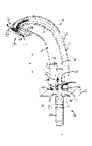
[0015] FIG. 1 is a perspective view of an example modular faucet
assembly according
to the present disclosure;
[0016] FIG. 2 is a bottom perspective view of a seamless spout body of
the faucet of
FIG. 1 shown in isolation:
[0017] FIG. 3 is an enlarged partial perspective view of an outlet end of
the faucet of
FIG. 1 showing a sensor assembly exploded from the spout body;
[0018] FIG. 4 is a partial perspective view of a base end thereof
showing a modular
mounting base in exploded assembly;
[0019] FIG. 5A is a cross-section view taken along line 5-5 of FIG. 1
showing a spout
and mounting base thereof;
[0020] FIG. 5B is a cross-section view similar to FIG. 5A albeit showing
the spout
removed from the mounting base;
[0021] FIG. 6 is a partial perspective view of the base end of the
faucet of FIG. 1
showing a mounting shank and control module in exploded assembly;
[0022] FIG. 7 is an enlarged partial cross-section view taken along line 7-
7 of FIG. 1
showing the mounting shank and control module;
[0023] FIG. 8 is an enlarged partial perspective view of the outlet end
of the faucet of
FIG. 1 as taken along arc 8-8 of FIG. 5A;
[0024] FIG. 9 is an exploded view of the sensor assembly in isolation;
[0025] FIG. 10 is a perspective view of another example modular faucet
assembly
with above-deck mixing capabilities;
[0026] FIG. 11 is an exploded assembly view thereof without the control
module
shown in FIG. 10;
[0027] Fig. 12 is an enlarged partial cross-section view taken along
line 12-12 of FIG.
10 showing a base end of the faucet;
[0028] FIG. 13 is a partial cross-section view taken along line 13-13 of
FIG. 10
showing the base and control modules of the faucet;
[0029] FIG. 14 is an enlarged partial sectional view of a mixing valve
assembly of the
modular faucet assembly of FIG. 10;
[0030] FIG. 15 is a perspective view of the mixing valve of FIG. 10 in
isolation;
[0031] FIG. 16 is a plan view thereof; and
4
CA 02889844 2015-04-28
WO 2014/070918 PCT/US2013/067555
[0032] FIG. 17 is a perspective view of another example seamless spout
body design
that can be interchanged with the spout body of the faucet of FIG. 1.
[0033] Like reference numerals will be used to refer to like parts from
figure to figure
in the following detailed description.
DETAILED DESCRIPTION
[0034] A non-limiting example of a modular faucet assembly is
illustrated in FIGS. 1-
9. Referring to FIG. 1, a modular faucet assembly 100 includes a spout 110, a
base
module 120 and a control module 140. The base module 120 is mounted within a
mounting opening 102 in a surface 101, such as a sink deck (see FIGS. 5A-5B).
The
spout 110 removably couples to the base module 120, which extends through the
mounting opening 102 to below the deck 101. A portion of the base module 120
below
the deck 101 is coupled to the control module 140. The control module 140 is
configured
to couple to a fluid source, such as a building water supply, in order to
control the
passage of a fluid (e.g., water) to the base module 120 and the spout 110.
[0035] The spout 110 has an upper outlet end 111, a main body 112 and a
lower
base end 113. The spout 110 defines the external shell of the faucet 100 as
well as
internal wall structure 108 and 109 at or near the base 113 and outlet 111
ends,
respectively. The body 112 of the spout 110 houses a sensor module 130 in
electrical
communication with the control module 140. A lens 132 of the sensor module 130
is
disposed in the outlet end 111 of the spout 110. The position of the lens 132
enables the
sensor module 130 to detect motion beneath or sense proximity of an object to
the outlet
end 111. For example, the sensor module 130 can detect the placement of a hand
or a
hand motion. The outlet end 111 further includes a fluid outlet 117 in
communication with
the fluid source through which fluid can pass. In basic operation, the sensor
module 130
detects the object near the outlet end 111 of the spout 110 and signals the
control
module 140 to enable the passage of fluid from the fluid source, through the
base
module, into the spout body 112 and through the outlet 117. When the sensor
module
130 no longer detects the object, the sensor module 130 signals the control
module 140
to stop the passage of fluid from the source to the outlet 117. In summary,
the modular
faucet assembly 100 functions to allow a user to automatically wash his or her
hands by
simply positioning them beneath the sensor.
[0036] In one implementation, the spout 110 includes a bifurcated
interior defining a
dry chamber 115 and a wet chamber 116, both of which run between the base end
113
and outlet end 111 of the spout 110. Figures 1-9 illustrate one spout
configuration,
however, a bifurcated spout of other sizes and shapes can be used with this
construction
5
CA 02889844 2015-04-28
WO 2014/070918 PCT/US2013/067555
of the modular faucet assembly (see FIGS. 14-15). For example, the spout body
112 can
be of any suitable size and shape, including round or rectilinear sections and
profiles, and
can be monolithic, in other words a seamless, unibody construction, or an
assembly of
multiple sections. As mentioned, however, this example illustrates that the
modular
faucet can have a spout body 112 that integrally provides the waterway and
support
structure for the internal components.
[0037] As shown in FIGS. 2-5B, the spout body 112 can be a seamless
cast, unitary
hollow body that is bifurcated by an integral internal partition wall 114 into
two lengthwise
passages or chambers, such as dry 115 and wet 116 chambers that extend between
o opposite ends of the spout 110. As shown, the partition wall 114 can be
symmetrically or
asymmetrically disposed within the interior of the spout 110 to define two
equal or
unequal chambers. For example, the wet chamber 116 can have a larger volume,
and it
can converge somewhat from the mounting end 113 to the outlet end 111 of the
spout
110. The wet chamber 116 can extend to the base end wall 109 near the base end
113
of the spout 110 that couples to the base module 120. The base end wall 109
defines a
flow tube or pipe flow pipe 103, defining a flow passageway and extending
about an
upright axis A (see FIGS. 5A-5B) of the spout 110, but otherwise extends
across the wet
chamber 116 to close off its lower end. At the outlet end 111 of the spout 110
is the
outlet end wall 108 that has an outlet 117 for communicating water flow from
wet
chamber 116 and defining a recessed pocket in which an aerator 119 is mounted.
[0038] The dry chamber 115, which can be smaller in volume, opens at the
lower
base end 113 of the spout 110 either through another opening in the base end
wall 109,
or in the configuration shown in FIG. 2 by bypassing the base end wall 109.
The dry
chamber 115 extends to the outlet end 111 of the spout 110, either by
bypassing the
outlet end wall 108, or as shown in FIG. 2 through an opening 118 in the
outlet end wall
108. The internal partition wall 114 extends continuously and uninterruptedly
between
the end walls 108 and 109 and interior surfaces of the spout 110, and thus the
dry
chamber 115 is fluidly isolated from the waterway defined by the wet chamber
116. As
such, the dry chamber 115 can contain electrical conduit 137 for the sensor
module 130,
which can be mounted to the opening 118 in the outlet end wall 108, without
requiring
being specially encased or sealed off at either end of the spout 110.
[0039] Referring now to FIGS. 4 and 5A-5B, the base module 120 includes
a
mounting base 121 and a hollow rod mounting shank 122. The mounting base 121
has a
circular bottom wall, with an arc-shaped opening 128, and being sized larger
than the
mounting opening 102 so that the mounting base can be mounted to an upper
surface of
deck 101, while the mounting shank 122 extends through the mounting opening
102 of
6
CA 02889844 2015-04-28
WO 20141070918 PCT/US2013/067555
the deck 101. A narrow upper end 163 of the mounting shank 122 couples to the
mounting base 121 above the deck 101 while an externally threaded lower end
164
extends below the deck 101. A nut or other fastener 167 (shown in phantom in
FIGS. 1
and 5A-5B) can thread onto the lower end 164 and be tightened to clamp the
deck 101
between the mounting base 131 and the fastener 167. The mounting base 121
includes
a centrally positioned flow tube or pipe 127, defining a flow passageway
therein and
extending along the upright axis A of the spout 110 and can be sized to nest
with, for
example fit in close relation to and coaxially within, the flow pipe flow pipe
103 of the
base end wall 109 of the spout 110. The flow pipe 127 can have one or more,
such as
io two axially spaced apart, circumferential grooves for positioning 0-
rings 123a spaced
apart along the length of the flow pipe 127. The 0-rings 123a can create a
fluid tight seal
between the flow pipes 103 and 127. A cylindrical peripheral wall 129 extends
about the
upright axis A at the periphery of the mounting base 121. A circumferential
groove 104 in
the peripheral wall 129 accommodates an 0-ring 124. A cylindrical opening 168,
or an
enlarged portion of the flow pipe 127, receives the upper end 163 of the
mounting shank
122. The mounting shank 122, has a circumferential groove 162 positioned
between the
upper end 163 and a flange 161 having a greater diameter than the upper end
163
received in the mounting base 121. The groove 162 accommodates an 0-ring 123b
for
forming a fluid tight seal with an interior wall of the mounting base 121 at
the cylindrical
opening 168 in conjunction with the flange 161, which abuts a bottom surface
of the
mounting base 121. Note that while flow pipes 103 and 127 are shown to be
cylindrical,
flow pipes having different cross sections, for example including rectangular,
oval or "D"-
shaped can be used, provided the flow pipes are complementary. Furthermore,
the flow
pipes can be either coaxial with a central axis of the spout such as upright
axis A, or on
other axis different from the central axis of the spout. Still further, while
both the base end
wall 109 of the spout 110 and the mounting base 121 are shown and described
herein as
defining integral flow pipes, only one of these components could be configured
with a
flow pipe. The other could be an opening of complementary shape, such as in
the base
end wall 109, to receive the flow pipe 127 without having a corresponding
length that
extends along and nests with the flow pipe 127.
[ONO] With reference to FIGS. 5A and 5B, the base end 113 of the spout
110 is
configured to couple to the mounting base 121 by simply fitting the spout 110
down over
the mounting base 121 in a simple plug-in type connection. The spout 110
decouples
from the mounting base 121 by simply unplugging it (i.e., lifting it up and
away from the
mounting base 121). More specifically, the spout 110 interfaces with the
mounting base
121 primarily (if not entirely) at the interface of the flow pipes 103 and 127
with each
7
CA 02889844 2015-04-28
WO 2014/070918 PCMJS2013/067555
other and the interface of the spout body 112 and the peripheral wall 129.
That is, in the
example faucet 100, the spout 110 is positioned so that the flow pipe 103
formed in the
base end wall 109 extends downwardly along the upright axis A and is fit
around the flow
pipe 127, which extends upwardly along the upright axis A. At the same time,
the base
end 113 of the spout 110 fits coaxially around the peripheral wall 129 of the
mounting
base 121. The nested structures can be brought in close relation, and if
desired can be
sized to contact the associated nested structure. The 0-rings 123a and the 0-
ring 124
provide a snug, solid connection, and as mentioned at the interface of the
flow pipes 103
and 127, a fluid tight seal. 0-rings 123a and 124 thus further contribute to
the coupling of
o the spout 110 to the mounting base 121. Further, when assembled, the
mounting base
121 can be completely or partially concealed by the spout 110.
[0041] The example modular assembly of the faucet 100 allows the same
base
module 120 and control module 140 to be used with different spouts. For
example, this
modular construction permits replacement of the spout of previously installed
faucet for
functional or aesthetic reasons without replacing, or even disassembling, the
other
components of the faucet. Spouts having different external configurations but
a common
interface at the base end can be interchangeably mounted to the base module
120,
thereby allowing for the faucet to be given an entirely different look, since
the spout is the
primary, if not only, externally visible component above the mounting deck.
Moreover,
the spout can be installed and removed from above the mounting deck to
accommodate
a wider range of spout designs and sizes, where only the spout 110 and sensor
module
130 would be replaced.
[0042] The aforementioned connection is sufficient to securely couple
the spout 110
to the mounting base 121 as needed during use of the faucet 100. However, the
spout
110 can be further secured to the mounting base 121 so as to prevent unwanted
rotation
or removal of the spout 110 from the mounting base 121, for example, thus
making it
tamper resistant for use in public washrooms. For example, to further secure
the spout
110 to the mounting base 121, two openings 106 can be located in the
peripheral wall
129 of the mounting base 121 to receive fasteners 125 and 126. In one
embodiment, the
fastener 125 is a spring-biased locking pin and the fastener 126 is a screw.
The spout
110 then has at least one hole 105 for aligning the spout 110 with the
mounting base 121
and for receiving fasteners 125 and 126.
[0043] Various other mechanisms and fasteners can be used in addition to
or in place
of fasteners 125 and 126 to removably secure the spout 110 to the mounting
base 121,
including without limitation threaded fasteners, rivets, magnets, a threaded
connection
between the spout and mounting base, adhesives, welds, solder and a press-fit.
The
8
mounting base 121 can have a pocket that receives a movable detent or other
mechanical
locking features. Furthermore, the peripheral wall 129 of the mounting base
121 can have
a keyed shape that corresponds to a keyed opening defined by an interior
surface of the
base end 113. For example, the peripheral wall 129 can have a D-shape
with the inner surface of the base end 113 having a complementary shape to
align with
the mounting base 121 in a predetermined manner. The choice of a keyed inner
face of the
peripheral wall 129 illustratively prevents the complementary base end 113 of
the spout 110
from rotating about the upright axis A. Alternatively, or in addition, flow
pipe 127 of the
mounting base 121 can have a keyed shape that corresponds to a keyed
opening defined by an interior surface of the flow pipe flow pipe 103 of the
spout 110. By
analogy, the keyed face of the flow pipes would illustratively prevent the
spout 110 from
rotating about the upright axis A.
[0044] Various mechanisms can be used to disconnect the spout 110 from
the
mounting base 121 depending on the connection mechanism employed, including
without
limitation suitable tools (e.g., screwdriver, wrench, hex wrench, pliers,
etc.) and solvents.
And, even various mechanisms can be used to release the spring-biased locking
pin. For
example, the locking pin can be magnetic, and held in a magnetically
insulating collar or
guide, such that magnetic flux from a magnetic key of opposing polarity can
drive the pin to
compress the spring sufficiently so that the pin is no longer within a pocket,
in which
case the spout 110 can be simply lifted up from the base 121. A mechanical
device,
such as a small tool, pin, clip or the like can be used inserted into an
opening in the spout
110 to directly contact the pin and drive it back against the spring to
release the spout 110.
Both options provide a tamper-resistant means of both locking and releasing
the spout
110.
[0045] The base module 120 can be any suitable construction such as cast or
machined brass, molded plastic, or composite plastic with brass inserts. Also,
suitable
seals, gaskets and other connectors can be used in addition to or in place of
0-rings 123
and 124 to provide water-tight connections at the spout-base module interface.
Watertight
connections can also be included for assembling the sensor module 130 and the
aerator 119 with the spout 110. Moreover, the spout 110 can be secured to the
base
module 120 in any suitable manner, including the spring-biased locking pin and
removable
connection mechanisms to provide a tamper-resistant connection of the spout
110 to the
deck 101.
[0046] Referring now to FIGS. 6 and 7, an example control module 140
of the
modular faucet assembly 100 is shown. The control module 140 includes a
solenoid
valve 142, including a spring biased plunger 176, wire coil 177 and valve head
178,
9
Date Recue/Date Received 2021-10-12
CA 02889844 2015-04-28
WO 2014/070918 PCT/US2013/067555
which is operated by a battery powered electronic control unit 179. The
control module
140 further includes a valve body 141 with upper and lower threaded ends 154
and 157,
respectively. A water supply line (not shown) connects to the lower threaded
end 157 to
provide water to the valve body 141 and an inlet orifice 169 metered by the
solenoid
valve 142. The threaded end 164 of the mounting shank 122 couples to the upper
threaded end 154 of the valve body 141. A gasket 144 is positioned between the
threaded end 164 of the mounting shank 122 and the outlet end 154 of the valve
body
141 to form a water-tight seal. The valve body 141 is in fluid communication
with a valve
housing 156. The valve housing 156 has a passage 155 in which the solenoid
valve 142
1 o is located. Energizing the solenoid valve 142 moves the plunger 176
along its stroke axis
to unseat the valve head 178 to permit fluid flow through the valve body 141.
The valve
housing 156 is sealed by coupling to a spray shield 143, which also contains a
recess
158 for accommodating the plunger 142. The plunger housing 156 and spray
shield 143
can be coupled together with fasteners 151.
[0047] In addition to
sealing the valve housing 156, the spray shield 143 functions to
protect the components of the battery powered electronic control unit 179. The
electronic
control unit 179 includes an electronics housing 146 of which an end wall is
formed by
spray shield 143. A gasket 150 is positioned between the housing 146 and the
spray
shield 143 to form a water-tight seal. The electronics housing 146 contains a
printed
circuit board (PCB) 149 containing suitable control electronics, such as a
microprocessor,
a memory storage device storing executable commands and control data, timing
circuitry
and the like (not shown). The PCB 149 is in electrical communication with the
sensor
module 130, the solenoid valve 142 and a power supply or battery pack 145. One
example of a suitable battery pack includes one or more AA batteries. A
threaded bolt
159 extending from battery pack 145 is positioned in a compartment 165 of
housing 146
in order to couple to a hex nut 147 positioned in an opposing face of the
compartment
165. The result is that battery pack 145 is coupled to the electronics housing
146.
[0048] An
additional component of the control module 140 is a wire, bus or other
electrical conduit 148 with a terminal connector 153. The
conduit 148 is in
communication with the PCB 149 for receiving signals from sensor module 130. A
sensor conduit (wire, bus, etc.) 137 of the sensor module 130 terminates in a
sensor
connector 138 which couples to connector 153. Figures 4 and 5A-5B illustrate
an
example path of the sensor conduit 137. Specifically, the conduit 137 is
routed from the
outlet end 111 of the spout 110, through the dry chamber 115, and through the
opening
128 in the mounting base 121. The conduit 137 is connected below the deck 101
to
conduit 148 by way of the connectors 138 and 153. Thus, the PCB 149 receives
an input
CA 02889844 2015-04-28
WO 2014/070918 PCT/US2013/067555
signal from the sensor module 130 via conduit 137 when the presence of a hand
or other
object near the spout 110 is sensed and energizes the solenoid valve 142 to
open, and
thereby water to flow through the valve body 141, into the mounting shank 122,
through
the flow pipes 103 and 127, into the wet chamber 116 of the spout 110 and out
through
the outlet. The control circuitry can then close the solenoid valve 142 after
receiving
input from the sensor module 130 that the object has been removed from nearby
the
spout 110. As is known, timing circuitry can be used to provide flow for pre-
set time
period in order to resist tampering.
[0049] Referring to FIG. 9, the components of an example sensor module
130 will
now be described. The sensor module 130 includes a sensor board 134 connected
to
conduit 137. A portion of the sensor board 134 is nested in a bezel 133, which
in turn is
nested in a housing 139. A lens 132 is positioned on one end of the housing
139, while
the conduit 137 extends out of the opposing end of the housing 139. Figure 9
further
shows a fastener 135 and retaining ring 136 for positioning the sensor module
130 in the
spout 110 as well as an 0-ring 131 for providing a water-tight seal.
[0050] Turning now to FIG. 3, integration of the sensor module 130 into
the outlet end
111 of the spout 110 is shown. An opening 118 in the outlet end wall 108 of
the spout
110 is sized to accommodate the housing 139 of the sensor module 130. The 0-
ring 131
is positioned around the housing 139 and between the lens 132 and the opening
118 to
form a water-tight seal. The fastener 135 is routed through a hole in the lens
132 and
can be held in place prior to installation by the retaining ring 136. The
fastener 135 is
received in a hole above the opening 118 in order to couple the lens, and
therefore the
sensor module 130 to the spout 110. Figure 1 shows a view of the assembled
spout 110
with the sensor module 130, where only the lens 132 and fastener 135
components are
visible.
[0051] As shown in FIG. 5A, the end of the sensor module 130 including
the sensor
board 134 is positioned in the outlet end wall 108 of the spout 110. The
conduit 137 in
connection with the sensor board 134 exits the housing 139 and travels through
the spout
110 to the space below the deck 101. From FIG. 8, it can be seen that an
overhanging
surface 107 of the spout 110 extends below lens 132, as well as the rest of
the sensor
module 130 with the exception of the conduit 137 and connector 138 by virtue
of the
passage of the conduit through the spout 110 and below the deck 101. The
fastener 135
is shown to pass through the lens 132 and into the end wall 108 of the spout
110.
Furthermore, the housing 139 is positioned in the dry chamber 115. A view of
the nested
housing 139, bezel 133 and sensor board 134 is also shown. As shown, both the
sensor
11
module 130 and the aerator 119 are essentially concealed from the view of a
user by an
overhanging surface 107 of the spout 110.
[0052] With continued reference to FIG. 8, the positioning of the
sensor module 130 is
shown with respect to aerator 119. In some embodiments of the modular faucet
assembly 100, the aerator 117 is illustratively mounted at an angle, a,
relative to the
lens 132 of the sensor module 130. In particular, an end face 119a of the
aerator 119
visible from beneath the outlet end 111 of the spout 110 is mounted such that
the end face
119a is positioned in a first plane, Pi. Moreover, an end face 132a of the
lens 132 visible
from beneath the outlet end 111 of the spout 110 is mounted such that the end
face 132a is positioned in a second plane, P2, at the angle, a, relative to
the first plane Pi
Generally, the angle a has a value from about 0 to about 10 , illustratively
about 3 to
about 7 and further illustratively about 5 . Mounting the aerator 119 in a
plane at a
prescribed angle in this manner from the angle of the plane of the lens 132
provides several
intended advantages. For example, when the faucet is in operation, a water
stream
flowing from the fluid outlet 117 is angled away from the lens 132 of the
sensor module
130. Therefore, the lens 132 is less susceptible to either splashing or false
detection of the
water stream as an object by the sensor module 130. Also, the lens 132 is
angled up from
the aerator 119 to detect objects positioned above the sink, whereas the
aerator 119 is
angled down from the lens 132 to direct a water stream flowing from the fluid
outlet 117
downward into the sink.
[0053] In FIGS. 1-8, the sensor module 130 is shown positioned above
the aerator 119.
However, in other embodiments, the sensor module 130 can be positioned above,
that is
outward of, the aerator 119, or below (or inward of) the aerator 119, or in
any other suitable
location or orientation to be able to detect the presence of an person's hands
or
other objects within the basin of the lavatory, without detecting the presence
of objects
elsewhere. The sensor module 130 and aerator 119 can be any suitable
conventional
devices, including known filter and aerator cartridges and any suitable
infrared,
capacitance, ultrasonic field or other known sensor technology for sensing the
presence
or motion of an object.
[0054] Turning now to FIGS. 10-16, a second non-limiting example of a
modular
faucet assembly 200 with an above deck mixing functionality is shown. Note
that parts
identified for the assembly 200 that correspond to parts identified for
assembly 100 are
labeled with like numbers. For example, spout 110 in assembly 100 corresponds
to spout
210 in assembly 200. Referring to FIG. 10, a modular faucet assembly 200
includes a spout 210, a base module 220 and a control module 240. The spout
210 is
mounted to a surface 201, such as a sink deck. The spout 210 removably couples
to the
12
Date Recue/Date Received 2021-10-12
CA 02889844 2015-04-28
WO 2014/070918 PCT/US2013/067555
base module 220, which in turn extends through the deck 201. A portion of the
base
module 220 below the deck 201 is coupled to the control module 240. Control
module
240 is configured to couple to a fluid source in order to control the passage
of a fluid
(e.g., water) to the base module 220 and the spout 210.
[0055] As described for assembly 100, the spout 210 includes an outlet end
211, a
body 212 and a lower base end 213. The spout 210 defines the external shell of
the
faucet 200 as well as internal wall structure 208 and 209 at or near the base
213 and
outlet 211 ends, respectively. The body 212 of the spout 210 houses a sensor
module
230 in electrical communication with the control module 240. A lens 232 of the
sensor
io module 230 is disposed in the outlet end wall 208 of the spout 210. The
position of the
lens 232 enables the sensor module 230 to detect the presence or motion of an
object
beneath the mouth 211. The outlet end wall 108 further includes a fluid outlet
217 in
communication with the fluid source through which fluid can pass. As in
assembly 100,
the modular faucet assembly 200 functions to allow a user to automatically
wash his or
her hands by simply placing his or her hands in the path of the sensor.
[0056] An additional component of spout 210 is an on-board, or above
deck mounted
(ADM), mixing valve module 280 for mixing multiple fluid streams, such as
relatively cold
and hot water flow streams. In order to accommodate the manually-operable
mixing
valve 280 in the faucet 200, the spout 210 includes an opening 202 for
connecting the
control lever or handle 281 to the mixing valve module 280 so that it is
accessible when
the faucet is fully assembled, as shown in FIG. 10.
[0057] Figure 10 also shows additional components of assembly 200 that
are located
below the mounting deck, including a branch connector tube 270. Branch
connector tube
270 couples base module 220 to a first valve body 241 of control module 240 as
well as a
second valve body 341 (parts identified for the control module 340, including
valve body
341, correspond to parts identified for control module 240, and are labeled
with like
numbers). The faucet assembly 200 includes two solenoid valves 242 and 342 in
order
to accommodate two fluid streams. In one aspect, a first solenoid valve 242
regulates
the supply of a relative cold water source while a second valve 342 regulates
the supply
of a relatively hot water source. As a result, cold and hot water sources can
be mixed
through operation of ADM module 280 to regulate the temperature of the water
exiting
the spout 210.
[0058] As with spout 110, in one implementation spout body 212 has a
bifurcated
interior defining a dry chamber 215 and a wet chamber 216, both of which run
between
the lower end 213 and outlet end 211 of the spout 210 (see FIG. 12). Figures
10-16
illustrate one spout configuration, however, a bifurcated spout of other sizes
and shapes
13
CA 02889844 2015-04-28
= WO 2014/070918
PCT/US2013/067555
can be used with this construction of the modular faucet assembly 200. Also,
the spout
body 212 can be of any suitable size and shape, including round or rectilinear
sections
and profiles, and can be monolithic (e.g., a seamless casting) or an assembly
of multiple
sections.
[0059] Referring now to FIGS. 11-13, the base module 220 includes a
mounting base
221 and a mounting shank 222. The mounting base 221 is mounted to an upper
surface
of deck 201, while the mounting shank 222 extends through the mounting opening
in the
deck 201. An upper end of the mounting shank 263 couples to the mounting base
221
above the deck 201 while a lower threaded end 264 of the mounting shank 222
can be
io secured below deck 201 with a nut or other fastener 267 (shown in
phantom in FIG. 10).
The mounting base 221 includes a centrally positioned flow pipe 227 having
grooves for
positioning two 0-rings 223 spaced apart along the length of the flow pipe
227.
Furthermore, a groove 204 is positioned in a peripheral wall 229 of the
mounting base
221 to accommodate an 0-ring 224. The interior of the flow pipe 227 is shaped
to
receive the upper end 263 of the mounting shank 222.
[0060] Referring to FIGS. 11-13, the mounting shank 222 is
bifurcated by a partition
wall defining two distinct passages 295 and 296. The passages 295 and 296
terminate
at openings 266 at each end of the mounting shank 222. The first passage 295
is in fluid
communication with a first fluid source, such as a relatively cold or hot
water source, by
way of passage 272. Similarly, the second passage 296 is in communication with
a
second fluid source, such as a relatively hot or cold water source, by way of
passage
271. Passage 271 is not in fluid communication with passage 272. Thus, for
example,
separate water streams can pass respectively through the passages 295 and 296
to
components of the ADM module 280 in mounting base 221 as discussed below.
Although the illustrated mounting shank 222 is bifurcated, alternative
mounting shank 222
designs are possible. For example, a mounting shank 222 can include a first
tube
positioned with a second tube, wherein each tube defines a single passage.
Water-tight
seals on the ends of the tubes can maintain two distinct flow passages in
order to
achieve a similar result to the bifurcated mounting shank 222.
[0061] Additional components of base module 220 include a disk 292
positioned
between the mounting base 221 and the upper end 263 of the mounting shank 222.
The
disk 292 includes holes 294 that align with channels 266 in the mounting shank
222 to
allow for fluid flow between the mounting shank 222 and the mounting base 221.
A ring
290 and a bracket 291 are also disposed between the mounting base 221 and deck
201.
As shown in FIG. 12, the ring 290 also contacts the lower end 213 of the spout
210 while
bracket 291 slots into a recess in the mounting base 221.
14
CA 02889844 2015-04-28
WO 2014/070918 PCT/US2013/067555
[0062] The mounting base 221 further includes a valve housing 289 for
the mixing
valve or mixing spool 288 of ADM module 280. The valve housing 289 is a
crosswise
bore that intersects the flow pipe 227 of the mounting base 221 such that
mixing spool
288 can operate to regulate the flow out hot and cold water sources in order
to regulate
the temperature as described above. The mixing spool 288 couples to handle 281
through an opening in spout 210 by way of a fastener 285 and end cap 282.
Seals, such
as 0-rings 283, 286 and 287 provide a water-tight seal between the valve
handle 281,
the mixing spool 288 and the mounting base 221.
[0063] Referring to FIGS. 11 and 14-16, the mixing spool 288 includes a
keyed end
face 402 configured to couple to handle 281. In particular, the inner surface
of the valve
handle 281 defining the space 284 is shaped so as to be complementary to the
keyed
end 402. When the mixing spool 288 is positioned in the valve housing 289 in
the
mounting base 221, a pin 404 can be inserted through an upper opening in the
mounting
base 221 in order to pass through a groove 406 in an end of the mixing spool
288. A
lower end 408 of the pin 404 can couple to the mounting base 221. With the pin
404 in
place, the mixing spool 288, and thereby the valve handle 281, are prevented
from
separating from the mounting base 221, while being able to rotate about an
axis
A', which can be aligned cross-wise, such as perpendicular, to the upright
axis A. By
sizing the circumferential extent of the groove 406, the mixing spool 288, and
thus the
valve handle 281, can be limited to rotate about axis A' through a prescribed
angle, such
as 30-60 degrees, as needed.
[0064] Referring to FIGS. 15-16, first and second flow channels 410 and
412 are
defined by a central portion 414 of the mixing spool 288. In addition, as
depicted in FIG.
14, a cavity 416 is defined, which is in communication with the first and
second channels
410 and 412. In operation, when the mixing valve 288 is positioned within the
valve
housing 289 as depicted in FIG. 14, the first and second flow channels 410 and
412 are
in fluid communication with the passages 295 and 296 in the mounting shank
222. This
configuration allows the separate fluid streams (e.g., relatively cold and hot
water) to flow
in equal proportion into the cavity 416, through the flow pipe 227 and into
the spout
210. However, when the valve handle 281 is rotated on the axis A', the mixing
spool 288
is rotated within the valve housing 289 such that the flow channels 410 and
412 are
positioned to restrict or increase fluid flow from the passages 295 and 296.
For example,
in the illustrated example if the valve handle 281 is turned fully
counterclockwise, the
mixing spool 288 would rotate about axis A' so that the channel 410 would
enable flow
from the second passage 296 to remain fully open, whereas the channel 412
would be
shut off from the passage 295, since the central portion 414 of the mixing
valve 288
CA 02889844 2015-04-28
WO 2014/070918 PCT/US2013/067555
would obstruct the fluid flow from passage 295. Conversely, if the user were
to turn the
valve handle 281 fully clockwise, the channel 412 would enable flow from the
passage
295 while the flow from passage 296 would be restricted, since in this case
the central
portion 414 of the mixing spool 288 would obstruct the fluid flow from passage
296. When the valve handle 281 is at some intermediate position between the
midpoint
and either fully clockwise or fully counterclockwise, the mixing spool 288
will allow
proportional mixing of the fluid streams. It should be noted that the flow
channels 410
and 412 can have rectilinear cross-sections, square in the illustrated
example. This
configuration has the effect of providing a more linear mixing ratio of the
two fluid streams
io passing through the mixing spool 288, that when compared to circular or
other non-linear
cross-sectional configurations.
[0065] As with spout 110, the base end 213 of the spout 210 is
configured to couple
to the mounting base 221 by simply fitting the spout 210 down over the
mounting base
221 in a simple plug-in type connection. The spout 210 decouples from the
mounting
base 221 then by simply unplugging it (i.e., pulling it up and away from the
mounting
base 221). More specifically, the spout 210 interfaces with the mounting base
221
primarily (if not entirely) at the interface of the flow pipes 203 and 227
with each other
and the interface of the spout body 212 and the peripheral wall 329. In the
example
faucet 200, the spout 210 is positioned so that the flow pipe 203 formed in
the base end
wall 209 extends downwardly along the upright axis A and is fit around the
flow pipe 227,
which extends upwardly along the upright axis A. At the same time, the base
end 213 of
the spout 210 fits coaxially around the peripheral wall 229 of the mounting
base 221. The
nested structures can be brought in close relation, and if desired can be
sized to contact
the associated nested structure. The 0-rings 223a and the 0-ring 224 provide a
snug,
solid connection, and as mentioned at the interface of the flow pipes 203 and
227, a fluid
tight seal. 0-rings 223a and 224 thus further contribute to the coupling of
the spout 210
to the mounting base 221. Further, when assembled, the mounting base 221 can
be
completely or partially concealed by the spout 210.
[0066] The example modular assembly of the faucet 200 allows the same
base
module 220 and control module 240 to be used with different spouts. For
example, this
modular construction permits replacement of the spout of previously installed
faucet for
functional or aesthetic reasons without replacing, or even disassembling, the
other
components of the faucet. Spouts having different external configurations but
a common
interface at the base end can be interchangeably mounted to the base module
120,
thereby allowing for the faucet to be given an entirely different look, since
the spout is the
primary, if not only, externally visible component above the mounting deck.
Moreover,
16
CA 02889844 2015-04-28
WO 2014/070918 PCT/US2013/067555
the spout can be installed and removed from above the mounting deck to
accommodate
a wider range of spout designs and sizes, where only the spout 210 and sensor
module
230 would be replaced.
[0067] The aforementioned connection is sufficient to securely couple
the spout 210
to the mounting base 221 as needed during use of the faucet 200. However, the
spout
210 can be further secured to the mounting base 221 so as to prevent unwanted
rotation
or removal of the spout 210 from the mounting base 221, for example, thus
making it
tamper resistant for use in public washrooms. For example, to further secure
the spout
210 to the mounting base 221, two openings 206 can be located in the
peripheral wall
io 229 of the mounting base 221 to receive fasteners 225 and 226. In one
embodiment, the
fastener 225 is a spring-biased locking pin and the fastener 226 is a screw.
The spout
210 then has at least one hole 205 for aligning the spout 210 with the
mounting base 221
and for receiving fasteners 225 and 226. As described for faucet assembly 100,
various
mechanisms and fasteners can be used in addition to or in place of fasteners
225 and
226 to removably secure the spout 210 to the mounting base 221, including
without
limitation threaded fasteners, rivets, magnets, a threaded connection between
the spout
and mounting base, adhesives, welds, solder and a press-fit. Furthermore,
various
mechanisms can be used to disconnect the spout 210 from the mounting base 221
depending on the connection mechanism employed, including without limitation
suitable
tools and solvents as above. Additionally, the base module 220 can be any
suitable
construction such as cast or machined brass, molded plastic, or composite
plastic with
brass inserts. Also, suitable seals, gaskets and other connectors can be used
in addition
to or in place of 0-rings 223 and 224 to provide water-tight connections at
the spout-base
module interface. Water-tight connections can also be included for assembling
the
sensor module 230 and the aerator 219 with the spout 210.
[0068] Referring now to FIG. 13, the control module 240 of the modular
faucet
assembly 200 is shown. The control module 240 includes a first 242 and second
342
solenoid valves operated by a battery powered electronic control module 279.
The
solenoid valve 242, including a spring biased plunger 276, wire coil 277 and
valve head
278, which is operated by the battery powered electronic control unit 279.The
control
module 240 further includes a solenoid valve body 241 with upper and lower
threaded
ends 254 and 257, respectively. The lower, hollow, threaded end 264 of shank
222 is
designed to couple to an upper end 273 of connector 270. Connector 270 has a
first
passage 272 with a lower end 274 and a second passage 271 with a lower end
275. The
lower end 274 is in fluid communication with the upper end 254 of valve body
241.
Suitable seals are positioned between each of the fluid connections for
connector 270.
17
CA 02889844 2015-04-28
WO 2014/070918 PCT/US2013/067555
[0069] A first water supply line (not shown) connects to the lower end
257 to provide
water to the solenoid valve inlet 269. The valve body 241 is in fluid
communication with a
plunger housing 256. The plunger housing 256 has a passage 255 in which
plunger 242
is positioned to regulate fluid flow through the valve body 241. Energizing
the solenoid
valve 242 moves the plunger 276 along its stroke axis to unseat the valve head
278 to
permit fluid flow through the valve body 241. The plunger housing 256 is
sealed by
coupling to spray shield 243, which also contains a recess 258 for
accommodating
plunger 242. The plunger housing 256 and spray shield 243 can be coupled
together
with fasteners 251.
[0070] In addition to sealing the plunger housing 256, the spray shield 243
functions
to protect the components of the battery powered electronic control module.
The
electronic control module includes an electronics housing 246 of which an end
wall is
formed by spray shield 243. A gasket 250 is positioned between housing 246 and
spray
shield 243 to form a water-tight seal. The electronics housing contains a
printed circuit
board (PCB) 249 in electrical communication with the sensor module 230, the
solenoid
valve and a power supply or battery pack 245. One example of a suitable
battery pack
includes one or more AA batteries. A threaded bolt 259 extending from battery
pack 245
is positioned in a compartment 265 of housing 246 in order to couple to a hex
nut 247
positioned in an opposing face of the compartment 265. The result is that
battery pack
245 is coupled to the electronics housing 246.
[0071] A second water supply line (not shown) connects to the lower end
357 of valve
body 341 to provide water to the second solenoid valve inlet. The second
solenoid valve
342 includes a spring biased plunger 376, wire coil 377 and valve head 378,
which is
operated by the battery powered electronic control unit 279. The control
module 240
further includes a solenoid valve body 341 with upper and lower threaded ends
354 and
357, respectively. Connector 270 has a second passage 271 with a lower end
275. The
lower end 275 is in fluid communication with the upper end 354 of valve body
341.
Suitable seals are positioned between each of the fluid connections for
connector 270.
The valve body 341 is in fluid communication with a plunger housing 356. The
plunger
housing 356 has a passage 355 in which plunger 342 is positioned to regulate
fluid flow
through the valve body 341. The plunger housing 356 is sealed by coupling to
cover
panel 343, which also contains a recess 358 for accommodating plunger 342 (see
Fig.
10). The plunder housing 356 and cover plate 343 can be coupled together with
fasteners. The assembled housing contains additional elements of the solenoid
valve
such as a solenoid coil (not shown). In one embodiment, solenoid valves 242
and 342
are in electrical communication with PCB 249 of control module 240.
18
=
CA 02889844 2015-04-28
= WO 2014/070918
PCT/US2013/067555
[0072] An
additional component of the control module 240 is a wire, bus or other
electrical conduit 248 with a terminal connector 253. The
conduit 248 is in
communication with the PCB 249 for receiving signals from sensor module 230. A
sensor conduit (wire, bus, etc.) 237 of the sensor module 230 terminates in a
sensor
connector 238 which couples to connector 253. Figure 12 illustrates an example
path of
the sensor conduit 237. Specifically, the conduit 237 is routed from the
outlet end 211 of
the spout 210, through the dry chamber 215, and through the opening 228 in the
mounting base 221. The conduit 237 is connected below the deck 201 to conduit
248 by
way of the connectors 238 and 253. Thus, the PCB 249 receives an input signal
from the
o sensor module 230 via conduit 237 when the presence of a hand or other
object near the
spout 210 is sensed and energizes the solenoid valves 242 and 342 to open, and
thereby
water to flow through the valve bodies 241 and 341, into the connector 270 and
bifurcated mounting shank 222 and on to ADM module 280 where the previously
distinct
streams are mixed. The mixed stream continues through the flow pipes 203 and
227,
into the wet chamber 216 of the spout 210 and out through the outlet 117. The
control
circuitry can then close the solenoid valves 242 and 342 after receiving input
from the
sensor module 230 that the object has been removed from nearby the spout 210.
As is
known, timing circuitry can be used to provide flow for pre-set time period in
order to
resist tampering.
[0073] Referring to
FIG. 11, an exploded view of the components of the sensor
module 230 is illustrated. In one aspect, the sensor module 230 is analogous
to sensor
130 of assembly 100. Sensor module 230 includes a sensor board (not shown)
connected to conduit 237. A portion of the sensor board is nested in a bezel
(not shown),
which in turn is nested in a housing 139. A lens 232 is positioned on one end
of the
housing 239, while the conduit 237 extends out of the opposing end of the
housing 239
(as for sensor module 130 in FIG. 9). Figure 11 further shows a fastener 235
and
retaining ring 236 for positioning the sensor module in the spout 210 as well
as an 0-ring
231 for providing a water-tight seal.
[0074] An
opening 218 in the mouth 211 of the spout 210 is sized to accommodate
the housing 239 of the sensor module 230. The 0-ring 231 is positioned around
the
housing 239 and between the lens 232 and the opening 218 to form a water-tight
seal.
The fastener 235 is routed through a hole in the lens 232 and can be held in
place prior
to installation by the retaining ring 236. The fastener 235 is received in a
hole above the
opening 218 in order to couple the lens, and therefore the sensor module 230
to the
spout 210. Figure 9 shows a view of the assembled spout 210 with sensor module
230,
where only the lens 232 and fastener 235 components are visible.
19
[0075] Again, the positioning and design of sensor module 230 are, in
one embodiment
equivalent to sensor module 130 as shown in Figs. 1-8. By extension, the
aerator 219 is
illustratively mounted at an angle, a, relative to the lens 232 of the sensor
module 230. In
particular, an end face of the aerator 219 is mounted such that
the end face is positioned in a first plane, Pi. Moreover, an end face of the
lens 232 is
mounted such that the end face is positioned in a second plane, P2, at an
angle, a, relative
to the first plane Pi. Generally, the a has a value from about 0 to about 10
, illustratively
about 3 to about 7 and further illustratively about 5 . Mounting the aerator
119 in a plane
at a prescribed angle in this manner from the angle of the plane of the lens
132
provides several intended advantages. For example, when the faucet is in
operation, a
water stream flowing from the fluid outlet 117 is angled away from the lens
132 of the
sensor module 130. Therefore, the lens 132 is less susceptible to either
splashing or false
detection of the water stream as an object by the sensor module 130. Also, the
lens 132
is angled up from the aerator 119 to detect objects positioned above the sink,
whereas
the aerator 119 is angled down from the lens 132 to direct a water stream
flowing from
the fluid outlet 117 downward into the sink.
[0076] In FIGS. 10-13, the sensor module 230 is shown positioned above
the aerator
219. However, in other embodiments the sensor module 230 can be positioned
above, that
is outward of, the aerator 219, or below (or inward of) the aerator 219, or in
any other
suitable location or orientation to be able to detect the presence of an
person's hands or
other objects within the basin of the lavatory, without detecting the presence
of objects
elsewhere. The sensor module 230 and aerator 219 can be any suitable
conventional
devices, including known filter and aerator cartridges and any suitable
infrared,
capacitance, ultrasonic field or other known sensor technology.
[0077] For this, or any of the other example faucet constructions, a
remotely mounted
ADM module for a motor-driven mixing valve can also be included with the
faucet and
operated by a master controller. Additionally, the faucet can be battery
powered and/or
include a low flow rate capable hydroelectric generator to recharge the
battery or directly
power the solenoid valves, control circuitry or other electronic components
mounted on or
used with the faucet. A latching type solenoid can be used in that case. An
example of a
commercially available battery-powered faucet with a hydro-generator and an
ADM
module is the Z6912-GEN-ADM EcoVantage Hydro Generator Faucet available from
Zurn
Industries, LLC.
[0078] Example faucets 100 and 200 provide a modular construction that
permits the
base modules 120, 220, water supply connections, and other below-the-deck
components of the faucet to be used with different faucet products. It also
allows the
Date Recue/Date Received 2021-10-12
spout, and internal components, to be replaced with another of the same or
different size,
shape or function, from above the mounting deck in a simple plug-in type
connection. A
suitable quick-disconnect can be provided for the sensor wire to further the
simple plug-in
connection of the faucet. Moreover, a mechanical or electronic interlock
feature can be
included to ensure that the spouts 100 and 200 are removed from the base
modules 120,
220 only when the water valve is closed.
[0079] It should be appreciated that the above generally describes
only exemplary
constructions of the modular faucet. Many modifications and variations to the
described
constructions will be apparent to those skilled in the art, which will be
within the
o scope of the disclosure. A non-limiting example of alternative spout 310
is depicted in
FIG. 17. As with spouts 110 and 210, spout 310 has an outlet end 311, a body
312 and a
lower base end 313. The spout 310 possesses a wide base 399 in order to
accommodate
alternative faucet designs, such as centerset faucet configurations. Despite
the different
configuration of the exterior of the spout body 312, the interface, that
is the base end wall 309, is configured in the same manner as base end wall
109, such
that it can be interchangeably mounted directly to the mounting base 121. For
example, a
cylindrical channel 303 is positioned in the end 309 to enable coupling to a
suitable base
module.
[0080] The terminology used herein is for the purpose of describing
particular
embodiments only and is not intended to be limiting of the disclosure. As used
herein,
the singular forms "a", "an" and "the" are intended to include the plural
forms as well, unless
the context clearly indicates otherwise. It will be further understood that
the terms
"comprises" and/or "comprising," when used in this specification, specify the
presence of
stated features, integers, steps, operations, elements, and/or components, but
do not
preclude the presence or addition of one or more other features, integers,
steps,
operations, elements, components, and/or groups thereof.
[0081] The description of the present disclosure has been presented
for purposes of
illustration and description, but is not intended to be exhaustive or limited
to the disclosure
in the form disclosed. Many modifications and variations will be apparent to
those of ordinary skill in the art without departing from the scope of the
disclosure. Explicitly referenced embodiments herein were chosen and described
in order
to best explain the principles of the disclosure and their practical
application, and to enable
others of ordinary skill in the art to understand the disclosure and recognize
many
alternatives, modifications, and variations on the described example(s).
Accordingly,
various embodiments and implementations other than those explicitly described
are
within the scope of the present invention.
21
Date Recue/Date Received 2021-10-12