Note : Les descriptions sont présentées dans la langue officielle dans laquelle elles ont été soumises.
CA 02890301 2015-05-04
WO 2014/082074
PCT/US2013/071976
METHODS AND SYSTEM FOR CONTROLLING
A LINEAR MOTOR FOR A DEEP WELL OIL PUMP
TECHNICAL FIELD
[0001] The
present invention relates generally to the field of oil and gas wells, and
more
particularly to a downhole linear motor pump system.
BACKGROUND ART
[0002] U.S.
Patent No. 1,655,825 is directed to a linear electromagnetic motor coupled to
an oil well pump. Solenoids are mounted within a casing and arranged to
actuate a core of
stacked magnets interspersed between non-magnetic members. The core is coupled
to a
pump plunger and an upper valve and two lower valves allow only upwards flow
of fluid.
[0003] U.S.
Patent No. 5,049,046 is directed to a downhole electromagnetic motor-pump
assembly having a linear motor, a pump having a reciprocating piston, and a
remote wireless
monitoring station.
US Patent No. 5,831,353 is directed to a motor-pump assembly having a positive
displacement pump and a motor for driving the pump to allow the fluids in the
production
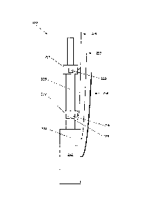
tube to be lifted to the upper ground level. A controller is provided for
controlling the linear
motor and supplies the motor with a certain number of direct current pulses.
BRIEF SUMMARY OF THE INVENTION
[0004] With
parenthetical reference to the corresponding parts, portions or surfaces of
the
disclosed embodiment, merely for the purposes of illustration and not by way
of limitation,
provided is a system (110) for operating a downhole pump with a linear motor,
including a
pump system (122), a motor drive system (124), a control and communication
computer
system (126), and a power distribution system (128). The control computer
system, motor
drive system, and power distribution system may be contained in an
environmental protection
box (125). The system may include a GUI computer (130), a data server (134),
and a remote
management computer (138).
[0005] The pump
system may include a linear motor (222), a pump (228), and a motor
sensor package (224). The motor sensor package may include an SSI encoder
position
sensor, a motor temperature sensor, an inclinometer, and a fault sensor. The
pump may
include an inlet (227) and the inlet may have a temperature sensor (225) and a
pressure sensor
(226). The pump may also have an outlet (231), and the outlet may have a
pressure sensor
(229). The motor may receive power from a three phase motor power line (234).
The motor
1
CA 02890301 2015-05-04
WO 2014/082074
PCT/US2013/071976
sensor package may be connected to the control computer through a three
twisted pair
connection (237). The inlet and outlet pressure sensors and temperature sensor
may be
connected to the control computer through a line (239) which uses a
transducer.
[0006] The
motor drive system (124) may include a motor drive unit (318) and a SINE
filter (321). The motor drive unit may be configured and arranged to receive
and transmit
transducer twisted pair lines from the pump system. The motor drive unit may
support a field
bus interface (326). The field bus interface may include DeviceNet, RS485, F-
NET, Modbus,
FireWire, CANopen, Ethernet IP, ProfiNet, SERCOS, 12-bit Analog IN, 16-bit
Analog I/O,
and/or other similar bus hardware and protocols.
[0007] The
control and communication computer system may include a router (419), a
switch (421), a wifi access port (141), GSM modem (145), a satcom modem or
port (143),
and a single board computer (410). The control computer may include an
Ethernet (423) for
linking each of its components. The single board computer may include a PC-104
single
board computer or other embedded computer. The single board computer may have
an I/O
(425), a GPS (427), a CPU (429), a memory (431), and a power supply (433). The
control
computer system may include an RS-485 transducer interface (435) for
communication.
[0008] The
control and communication computer may have a control algorithm for
controlling the motor drive system, and/or pump system. The control algorithm
may control
the motor drive system and/or pump as a function of sensory data. The sensory
data may be
data from the pump system, the motor drive system, the power distribution
system, and/or the
data server. The control algorithm may be capable of recognizing several dyna
card
operating regimes and/or may be configured to adjust control of the motor
drive as a function
of recognizing dyna card operating regimes. The dyna card operating regimes
may include
bent or sticking barrels, worn or sticking barrels, severe gas compression,
gas compression,
gas locked pump, severe traveling valve leak or plunger leak, severe standing
valve leak,
leaking traveling valve or plunger, severe standing valve leak, or a
combination of leaking
standing and traveling valve and gas compression. Dyna card operating regimes
may further
include tubing movement, fluid pound, pump hitting, upstroke pump wear, worn
standing
valve, worn or split barrel, fluid friction, and/or drag friction.
[0009] The
power distribution system may include a three phase AC power input, and
may provide an AC power output and a DC power output. The power distribution
system
may include one or more circuit breakers (521, 523), a surge suppression unit
(522), a
transformer (524), a MOV suppression unit (525), and a fuse terminal
distribution block
(526). The power distribution system may further include a cooling thermostat
(537), a
2
CA 02890301 2016-10-20
52125-18
cooling fan or air conditioner (539), a heat thermostat (541), a heater relay
(528), and/or a
heater (529). The power distribution unit may further include an auxiliary
power outlet (530).
The power distribution unit may be configured and arranged to automatically
keep the
environmental protection box at a temperature within a predetermined
temperature range.
[0010] The GUI computer may contain a software application (131) for
allowing a
user (101) to view sensor data, and view and set control computer operating
parameters and
algorithms. The data server may contain a web application (136) for allowing a
user (102) to
link with a remote management computer (138) and allow user (102) to view
sensor data, and
view and set control computer operating parameters. The data server may
contain a database
for storing sensor data from the control computer. The sensory data may be
periodically
transferred from the control computer to the data server. The data server may
also be
configured to periodically transmit secondary operating parameters to the
control computer.
The secondary operating parameters may include the price of oil, and the price
of electricity.
The data server may be configured and arranged to operate a number of pump
systems.
[0010a] According to an embodiment, there is provided a downhole linear
motor pump
system comprising: a downhole linear electric motor having a stator and a
shaft configured to
move linearly relative to said stator; a downhole pump having an inlet, an
outlet, and a piston
coupled to said downhole linear motor shaft; a motor driver system connected
with said
downhole linear motor and configured to provide drive commands to said
downhole linear
motor; a surface control computer connected with said motor drive system and
configured to
control said downhole linear motor; a sensor system communicating with said
control
computer and configured to sense operating parameters of said downhole linear
motor; and
said sensor system comprising a downhole synchronous serial interface encoder
configured to
sense position of said motor shaft and a downhole temperature sensor
configured to sense the
temperature of said motor.
BRIEF DESCRIPTION OF THE DRAWINGS
[0011] FIG. 1 is a system block diagram of a first embodiment system.
[0012] FIG. 2 is a block diagram of the pump system shown in FIG. 1.
3
CA 02890301 2016-10-20
52125-18
[0013] FIG. 3 is a block diagram of the motor driver system shown in
FIG. 1.
[0014] FIG. 4. is a block diagram of the control and communication
computer shown
in FIG. 1.
[0015] FIG. 5 is a block diagram of the power distribution system
shown in FIG. 1.
[0016] FIG. 6. is a model schematic of the containment box of the system
shown in
FIG. 1.
[0017] FIG. 7 is a chart of dyna card pump operating regimes.
[0018] FIG. 8 is a second chart of dyna card pump operating regimes.
DETAILED DESCRIPTION OF THE PREFERRED EMBODIMENTS
[0019] At the outset, it should be clearly understood that like reference
numerals are
intended to identify the same structural elements, portions or surfaces
consistently throughout
the several drawing figures, as such elements, portions or surfaces may be
further described or
explained by the entire written specification, of which this detailed
description is an integral
part. Unless otherwise indicated, the drawings are intended to be read (e.g.,
cross-hatching,
arrangement of parts, proportion, degree, etc.) together with the
specification, and
3a
CA 02890301 2015-05-04
WO 2014/082074
PCT/US2013/071976
are to be considered a portion of the entire written description of this
invention. As used in
the following description, the terms "horizontal", "vertical", "left",
"right", "up" and "down",
as well as adjectival and adverbial derivatives thereof (e.g., "horizontally",
"rightwardly",
"upwardly", etc.), simply refer to the orientation of the illustrated
structure as the particular
drawing figure faces the reader. Similarly, the terms "inwardly" and
"outwardly" generally
refer to the orientation of a surface relative to its axis of elongation, or
axis of rotation, as
appropriate.
[0020]
Referring now to the drawings, and more particularly to FIG. 1, a system for
operating a deep oil well pump with a linear motor is provided, a first
embodiment of which
is generally indicated at 110. System 110 generally includes deep well pump
system 122,
motor driver 124, control and communication computer 126, and power
distribution system
128. Also part of system 110 are GUI computer 130, data server 134, and remote
management computer 138. Pump system 122 is driven by motor driver & interface
124.
Control and communication computer 126 provides motor driver 124 with command
signals
to properly drive pump system 122. Control and communication computer 126 also
contains
communication systems for interacting with data server 134 and GUI computer
130. Control
and communication computer 126 stores and relays sensory data from pump system
122 and
driver 124 to data server 134 and/or GUI computer 130. GUI computer 130
provides user
101 a user interface for reviewing sensory data and setting operational
parameters of control
and communication computer 126. Data server 134 includes web application 134
which
provides an interface to remote management computer 138. Through interaction
via web
application 136, remote management computer 138 provides user 102 with a user
interface
for reviewing sensory data and setting operational parameters of control and
communication
computer 126. Data server 134 also acts as a data storage for sensory data
received from
control and communication computer 126. Motor driver and interface system 124,
control
and communicating computer system 126, and power distribution system 128 may
all be
contained in a common box or cabinet 125 designed to provide protection from
the
surrounding environment.
[0021] System
110 provides high level and detailed remote control of deep oil well pump
system 122 with numerous features for highly efficient and safe operation.
Pump system 122
is arranged near the bottom of a deep oil well and has the primary purpose of
pumping oil up
to the surface of the oil well. Pump system 122 includes a linear
electromagnetic pump
motor. Pump system 122 contains several sensors for monitoring pump operation
and deep
oil well conditions. Pump system 122 is connected to motor driver and
interface 124.
4
CA 02890301 2015-05-04
WO 2014/082074
PCT/US2013/071976
[0022] Motor
driver 124 provides pump system 122 with the high powered power lines
for driving the linear electromagnetic motor. Motor driver and interface 124
also contains
data lines for relaying sensory data from pump system 122 and motor driver and
interface
124 to control and communication computer 126.
[0023] Control
and communication computer 126 contains a real time controller/CPU for
providing motor driver 124 with the proper gate drive signals for operating
pump system 122
with a desired movement profile. Computer 126 is arranged at the surface of
the deep oil
well. Control and communication computer 126 includes data sampling and
storage
mechanisms for receiving and storing sensory data from both pump system 122
and motor
driver 124.
Additionally, control and communication computer 126 includes
communications transceivers including wifi modem 141, satellite modem 143, and
cellular
data modem 145. The communications transceivers provide a network link to data
server
134. Control and communication computer may also optionally have a wired
network
connection to a network for connection to data server 134. Control and
communication
computer 126 includes data storage for storing operational parameters as well
as sensory data
logs. Control and communication computer 126 provides a local area network
(LAN) for
interfacing with GUI computer 130.
[0024] Power
for computer 126, and motor driver 124 is provided by power distribution
system 128. Power distribution system converts a high voltage AC voltage from
a supply
line into lower regulated voltage for computer 126 and motor driver 124. Power
distribution
system 128 includes transformers, filters, and monitoring sensors and
protection devices.
Sensory data is provided from power distribution system 128 to control and
communication
computer 126. Power distribution system 128 also receives control signals from
control and
communication computer 126.
[0025] GUI
computer 130 may be a portable computer brought by a service user 101 in
order to provide on-site maintenance and/or monitoring. Alternatively, GUI
computer may
be a desktop computer arranged and kept at the deep oil well surface in
proximity to control
and communication computer 126. GUI computer 130 interfaces to control and
communication computer 130 through a LAN provided by computer 126. GUI
computer 130
generally includes a display for providing user 101 a graphical user interface
for viewing
system operational data. Operational data includes sensory data from pump
system 122,
motor driver 124, power distribution system 128, and control and communication
computer
126. GUI computer 130 also provides user 101 with a mechanism for changing
operational
parameters of control and communication computer 126.
CA 02890301 2015-05-04
WO 2014/082074
PCT/US2013/071976
[0026] Data
server 134 is a server computer arranged at a location remote from the oil
well. Data server 134 is connected to network 132 which is linked to control
and
communication computer 126 through one of a variety of communication link
types,
including hardwire connection, or internet connection via wire, wifi,
satellite modem, and/or
cellular data connections. Data server receives sensory data logs from control
and
communication computer 126. Data server 134 contains web server/web
application 136 for
providing a client interface for viewing the sensory data logs on remote
management
computer 138. Web application 136 also provides a mechanism for setting the
control
parameters on control and communication server 126.
[0027] While
certain types of computers are described herein, processing and analysis
may be practiced with different computer configurations, including internet
appliances, hand-
held devices, wearable computers, multi-processor systems, programmable
consumer
electronics, network PCs, mainframe computers, a system on a chip, or a
programmable logic
device such as a FPGA (field programmable gate array) or a PLD (programmable
logic
device). Various alternative memory devices may be included with the computer,
such as
flash memory, a hard disk drive, or other solid state memory device. The
programming can
be embodied in any form of computer-readable medium or a special purpose
computer or
data processor that is programmed, configured or constructed to perform the
subject
instructions. The term computer or processor as used herein refers to any of
the above
devices as well as any other data processor. Some
examples of processors are
microprocessors, microcontrollers, CPUs, PICs, PLCs, PCs or microcomputers. A
computer-
readable medium comprises a medium configured to store or transport computer
readable
code, or in which computer readable code may be embedded. Some examples of
computer-
readable medium are CD-ROM disks, ROM cards, floppy disks, flash ROMS, RAM,
nonvolatile ROM, magnetic tapes, computer hard drives, conventional hard
disks, and servers
on a network. The computer systems described above are for purposes of example
only. An
embodiment of the invention may be implemented in any type of computer system
or
programming or processing environment. In addition, it is meant to encompass
processing
that is performed in a distributed computing environment, were tasks or
modules are
performed by more than one processing device or by remote processing devices
that are run
through a communications network, such as a local area network, a wide area
network or the
internet. Thus, the term computer is to be interpreted expansively.
[0028] FIG. 2
is a block diagram of pump system 122. Pump system 122 includes motor
222 arranged near the bottom of an oil well and down-hole pump 228. Motor 222
is a three
6
CA 02890301 2016-10-20
52125-18
phase permanent magnet linear electric motor having a stationary stator and a
sliding shaft. Motor 222
receives power from three phase power line 234 from motor driver 124. In some
implementations, the three
phase power line 234 uses a 4 conductor cable. Coupled to motor 222 is motor
sensor package 224. Motor
sensor package 224 includes a synchronous serial interface (SSI) encoder for
sensing the position of the
linear motor shaft, a temperature sensor for monitoring the motor temperature,
an inclinometer for
measuring the angle that the linear motor is mounted, and a circuit fault
detector. Motor 222 is coupled to
down-hole pump 228. Down-hole pump 228 includes a standing valve, a traveling
valve, a piston or
plunger, inlet 227, and outlet 231. Pump 228's piston is coupled to motor
222's shaft. As pump 228's piston
is forced up and down by motor 222, oil is drawn into inlet 227, and pushed up
out of outlet 231. Outlet 231
is coupled to production tubing leading to the surface of the oil well.
[0029] Inlet 227 has temperature sensor 225 for providing the temperature at
the inlet and pressure sensor
226 for providing oil or fluid pressure at the inlet. The inlet pressure can
be used to determine the depth of
oil remaining in the oil well. Outlet 231 includes pressure sensor 229. The
sensor output from inlet 227 and
outlet 231 are combined into a single conductor transducer interface 239.
Sensory data from motor sensor
package 224 is similarly combined into a 3 twisted pair interface. The data
interface may be implemented
using alternative protocols for either analog or digital signal transfer.
[0030] FIG. 3 is a block diagram of motor driver system and interface 124.
Motor driver system 124
includes motor drive unit 318 and SINE filter 321. In this embodiment, motor
drive unit 318 is a DS2110
servo drive from Moog Inc., East Aurora, NY, USA. However, other similar
electromagnetic motor drive
units may be used. Motor drive unit 318 receives sensory data lines 237 and
239. Motor drive unit 318
interfaces with control and communication computer 126 over digital interface
bus 326. Sensory data from
lines 237 and 239 is relayed to computer 126 over bus 326. Bus 326 is also
used by computer 126 to relay
drive commands to motor drive unit 318. Bus 326 has multiple protocols
implemented including
DeviceNet, RS485, F-NET, Modbus, FireWire, CANopen, Ethernet IP, ProfiNet, and
SERCOS. However,
other similar protocols may also be used as alternatives.
[0031] Motor drive unit receives high power and 24 volt DC line 329 from power
distribution system 128.
The 24 volt line 329 may or may not be relayed through the control and
communication computer 126.
[0032] FIG. 4 is a block diagram of control and communication computer system
126. Computer system
126 includes single board computer 410, which is implemented with a PC 104
computer. However, other
similar computers may be used for computer 410. Computer
7
CA 02890301 2015-05-04
WO 2014/082074
PCT/US2013/071976
system 126 includes router 419, switch 421, data transceivers for wifi 141,
and GSM cellular
modem 145. A satcom port 143 is provided for connection to a satellite
modem/antenna.
Switch 421 connects router 419, wifi transceiver 141, GSM modem 145, sitcom
port 143, and
single board computer 410 over an Ethernet 423. Router 419, wifi transceiver
141, GSM
modem 145, and satcom port 143 all provide external network connections for
single board
computer 410. This external network connection is primarily used for
communication
between single board computer 410 and data server 134.
[0033] Single
board computer 410 includes I/O 425, GPS 427, CPU 429, Memory 431,
and power supply 433. The Ethernet 423 connects to single board computer I/O
425. I/O
425 also interfaces with bus 326 and RS-485/RS232transducer interface 435.
[0034]
Application programs are stored in memory 431 and configured to run on CPU
429. More specifically, programs on single board computer 410 provide driver
control
signals to motor driver system 124, receive and record sensory data from pump
122, motor
driver 124, and power distribution system 128, upload data logs to data server
134 and/or
GUI computer 130, and receive configuration commands from data server 134
and/or GUI
computer 130.
[0035]
Additionally, programs on single board computer 410 may monitor the received
sensory data and alter the motor drive commands sent to motor driver system
124 as a
function of the received sensory data. More specifically, programs on computer
410 may
recognize one of several types of operating regimes, as specified in FIGS 7
and 8. FIGS 7
and 8 provide motor load vs. pump displacement curves for several known
operating regimes.
For example, as shown in FIG. 8, the "Ideal Card" curve is a rectangular load
vs
displacement curve for a single upwards and downwards stroke cycle of the
pump. Also, on
FIG. 8, the "Pump Hitting" curve shows how the motor load spikes at the top of
an upwards
stroke, and/or the bottom of a downwards stroke. These curves may also be
called
dynamometer cards. Computer 410 is programmed to recognize each of these
operating
regimes, and to trigger a warning and/or adjust pump operation based upon
these cards. For
example, if a "Pump Hitting" curve is recognized in the sensory data, computer
410 will
attempt to send a warning to data server 134, all GUI computers 130, and all
remote
management computers 138. Computer 410 will then adjust the drive command sent
to
motor driver 124 such that pump 122 is driven with a shorter stroke.
[0036] Programs
on single board computer 410 further implement communication
protocols for use in interacting on RS-485 transducer interface 435, the bus
interface 326, or
Ethernet 423. Programs on single board computer also include encryption and
compression
8
CA 02890301 2015-05-04
WO 2014/082074
PCT/US2013/071976
which are applied to transmissions between control and communication computer
system 126
and data server 134 and/or GUI computer 130. Programs on computer 410 may also
implement an FTP and telnet server. The FTP server may be used to receive and
transmit
files to computer 410. The telnet server may be used to provide a command
terminal for
viewing data stored on computer 410 or live from sensory data feeds. The
telnet server
command terminal may also allow control and communication computer 126's
control
parameters to be set.
[0037] FIG. 5
is a block diagram of power distribution system 128. Power distribution
system 128 receives power from AC mains 129, and provides power to system 110
via
240/120VAC line 519 and 24VDC line 329.
[0038] AC mains
129 is a 480 V three phase AC line in this embodiment. Power
distribution system 128 includes circuit breaker 521 connected to the three
phases of AC
mains 129. In this embodiment, circuit breaker 521 is a 30 amp three phase
disconnect
circuit breaker. Circuit breaker 521 passes the three phase power through
surge suppression
unit 522, which then makes the 480VAC signal available to the rest of pump
operation
system 110. Two of the phases from AC mains 129 is provided to two pole
circuit breaker
523. Circuit breaker 523 is a 10 amp breaker. Circuit breaker 523 provides two
phase AC
power to transformer 524. Transformer 524 is a 480/240/120 VAC transformer.
The outputs
of transformer 524 is passed through MOV suppression unit 525 before reaching
fuse
terminal distribution block 526. Terminal distribution block 526 provides the
connection
terminal for several electrical power output circuits, including 240/120 VAC
output line 519,
and 24VDC power supply line 329. The 120VAC line is provided to power
converter 531
which converts 120VAC to 24VDC. 24V0C may come directly from 3 ph 480 VAC. The
120VAC line is further used to provide power to lighting 533, door switch 535,
cooling
thermostat 537, cooling fan 539, and heat thermostat 541. The 480 volt surge
suppressed line
is used to provide power to heat relay 528 and heaters 529.
[0039] Cooling
and heating thermostats 537, 541, fan or AC unit 539, and heaters 529 are
used to keep the environment in box 125 within a desired temperature range.
[0040] GUI
computer 130 is a computer with a display, keyboard, and a network modem
(NIC). The network modem is used to connect GUI computer 130 to the LAN
provided by
control and communication computer 126. GUI computer 130 includes software
application
131. Software application 131 provides user 101 an interface for connecting to
control and
communication computer 126 for the purpose of viewing live and stored sensor
data, and for
viewing and setting control parameters of control and communication computer
126.
9
CA 02890301 2015-05-04
WO 2014/082074
PCT/US2013/071976
Software application 131 will further provide a graphical geographic view of
known pumps,
as well as provide basic operation statistics for each of the known pumps.
Software
application 131 may be a web browser, a telnet client, or, as in this
embodiment, a custom
software application.
[0041] After user 101 connects GUI computer 130 to control and
communication
computer 126's LAN, user 101 then starts application 131. Application 131
queries user 101
for a username and password, which are then provided to control and
communication
computer 126 for authentication. After authentication, application 131
provides user 101
several options. User 101 may select an option to view the current sensory
data of pump
control system 110. This causes application 131 to request a data stream from
control and
communication computer 126. Each of the raw sensor signals collected by
control and
communication computer 126 are forwarded to application 131 including motor
output force,
motor position, motor temperature, pump inlet and outlet pressure, inlet
temperature, pump
inclination, motor driver state, motor driver output current, power
distribution system state
and temperature, and power distribution system output voltage and current.
This data is
constantly streamed from control computer 126 to application 131, and is
ideally updated on
the GUI computer display in realtime. Application 131 may process the received
data and
may place the data into a graphical display. For example, the pump
displacement and motor
force output may be plotted in y vs x fashion in order to display data in the
same format as
the dyna card plots in FIG. 7 and FIG. 8.
[0042] User 101 may also select to view historical sensory data saved by
control
computer 126. For example, application 131 may request from control computer
126 the
sensory data from the last 1000 pump cycles. Upon receiving this data,
application 131 may
display this data in the form a plots with a time axis. For example, pump
displacement vs
motor force output could be plot as a 3D plot with a third axis for time (or
pump cycle
number). A color code can be applied to show a transition in the wear of the
system, such as
green for a "new" motor/pump to "red" which would indicate high wear and
actual damage
resulting in failure, thus requiring replacement. Further, the data viewed may
be time
averaged data based upon some time period. For example, each data point may be
the
average for a given data. More specifically, if user 101 is viewing the inlet
temperature,
application 131 may calculate and plot the average temperature for each day,
such that the
average temperature over a given day produces a single data point, and all the
datapoints over
a given time period are plotted with the day as the x axis variable and
temperature as the y
axis variable. Further, software application 131 may be used to display a
warning to user 101
CA 02890301 2015-05-04
WO 2014/082074
PCT/US2013/071976
which is generated by a program running on control computer 126. For example,
if a
program on control computer 126 recognizes that the motor force vs. pump
displacement data
produces a curve similar to one of the error conditions shown in FIGS. 7 or 8,
a descriptive
warning may be flashed on GUI computer 130's display.
[0043] Software
application 131 may also be used to adjust the operating parameters of
control computer 126. For example, after viewing sensory data, user 101 may
decide that the
pump should be operating at a decreased frequency. Application 131 provides
user 101 with
a command interface in order to set a new operating frequency. More
specifically,
application 131 allows user 101 to specify the exact movement profile that
pump system 122
is to be driven at. The movement profile may be a distance vs time curve, or a
force vs time
curve for a given operation cycle of the pump.
[0044]
Application 131 may further allow user 101 to program the operating function
that
control computer 126 is to follow based upon sensory data. For example, user
101 may
program control computer 126 to set the pump frequency to be equal to the
inlet pressure
times a constant. Other, more complex functions may be used to define the
movement profile
that control computer 126 is to command motor driver 124 based upon a whole
range of
sensory input conditions. For example, control computer 126 may be programmed
to
automatically adjust the movement profile based upon predefined conditions,
such as the
operating regimes defined in FIGS. 7 and 8. The movement profile may be
different for a
downstroke and upstroke, and may vary the frequency in realtime. User 101 may
further set
thresholds for defining when warnings should be generated by control computer
126.
[0045] Data
server 134 provides the functionality of GUI computer 130 to many potential
remote users 102, as well as acts as a data storage and backup facility. Data
server 134 also
acts as a mechanism to provide periodic data to control and communication
computer 126
which may affect the operating function of control computer 126.
[0046] All of
the functionality provided by application 131 is also available through web
application 136 running on data server 134. However, due to the higher latency
expected
between data server 134 and control computer 126, some of the real-time
functionality may
not be available. Web application is designed to act as a server core a client
remote
management computer 138. A user 102 may connect to web application 136 by
using a
standard web browser on remote management computer 138. In addition to be able
to view
the data stored on control computer 126, web application 136 provides the
ability to view
data stored on data server 134.
11
CA 02890301 2015-05-04
WO 2014/082074
PCT/US2013/071976
[0047] It may be advantageous to back up sensory data logs from control
computer 126 to
data server 134. For example, control computer 126 may send daily data logs to
data server
134. This allows redundant data to be deleted from control and communication
computer
126, such that a smaller data storage may be implemented on control computer
126. Also, by
having the sensory data stored on data server 134, historical data may be
provided to multiple
remote users over a faster and cheaper network link then would be possible if
each remote
user had to connect to the control and communication computer 126 themselves
(i.e. satcom
is typically slower and more costly than generic internet access). Also, by
having data server
134 provide data to remote users 102, the processing demand on control
computer 126 is
reduced.
[0048] Data server 134 may also be used to provide periodic data to control
computer 126
which is relevant to the method of pump operation. For example, the
international oil price
may be obtained by data server 134 and provided to control computer 126.
Control computer
126 may use the oil price as a variable in determining the operating
parameters. For example,
if the oil price is low, it may be more appropriate to operate the pump at a
lower frequency to
provide higher efficiency and less wear. However, if the oil prices has
significantly
increased, it may be advantageous to increase pump frequency in order to
capitalize on
selling more oil at the high price even at the cost of having increased pump
wear. Many
other variables may be periodically provided by data server 134 to control
computer 126 such
as electricity cost, weather conditions, predicted demand, shipping delays,
maintenance
schedules, and/or pipeline downtime schedules. Each of these variables would
be
appropriately incorporated into the operating algorithm on control computer
126.
[0049] The disclosed system and methods resulted in a number os surprising
results and
advantages. The disclosed system and methods allow for a health and usage
monitoring
system that is predictive and proactive instead of reactive in nature.
Advanced warning can
be given to technicians such that they can proactively take measures to
correct the motor or
pump performance before the motor or pump fails. This can save millions of
dollars in
maintenance costs and support.
[0050] This system can also measure and track trends such as rate of pump
wear or
variance in current vs. pressure to determine health and life of the system
and predict
maintenance intervals. The color coded scheme of displaying dyna card data,
combined with
the 3D representation of the data allows operators and technicians to quickly
and easily see
where/when a particular system entered into a failure state, or whether the
system is in a high
wear or low wear state. Further, this system allows greater accuracy in
determining down-
12
CA 02890301 2016-10-20
52125-18
hole conditions and provides a greater degree of automated control than is
available in prior
art systems.
[0051] The disclosed system provides for remote monitoring and
control via various
redundant communications channels including internet, wifi, cellular data
and/or satcom.
Further, a GPS system embedded in the control system will automatically locate
and map the
well for a remote management system.
[0051a] Referring now to FIG. 6, shown is a model schematic of the
containment box
125 of the system 110 shown in FIG. 1. The containment box 125 is shown with
very specific
components and configurations for exemplary purposes only. The containment box
125 has
Wifi circuitry 601, a power supply 602, an Ethernet router 603, an embedded PC
data I/O
interface 604, a lightning arrestor 605, a heater 606, a circuit breaker
disconnect 607, a line
transformer 608, a 115VAC outlet 609, a cooling unit 610, a thermostat 611, a
sine filter 612,
and a MOOG DS2110 brushless drive 613. In some implementations, the
containment box
125 is configured to communicate GSM cellular data and/or remote SatCom
signaling. The
containment box 125 may have other components and configurations, but they are
not shown.
[0052] Therefore, while the presently-preferred form of the down-hole pump
control system
has been shown and described, and several modifications discussed, persons
skilled in this art
will readily appreciate that various additional changes may be made without
departing from
the scope of the invention.
13