Note : Les descriptions sont présentées dans la langue officielle dans laquelle elles ont été soumises.
CA 02892186 2015-05-20
WO 2014/081445
PCT/US2013/000229
AXLE SHAFT SYSTEM FOR USE WITH GO-KARTS AND OTHER VEHICLES
SPECIFICATION
CROSS REFERENCE TO RELATED APPLICATIONS
[0001] The present application is a patent cooperation treaty (PCT)
application that
claims priority to U.S. Patent Application Serial No. 13/681,831, entitled
"Axle
Shaft System For Use With Go-Karts And Other Vehicles," filed November 20,
2012, which is incorporated herein in its entirety by reference.
FIELD
[0002] Embodiments usable within the scope of the present disclosure
relate, generally,
to configurations for vehicle axles, and more specifically, to axle shaft
systems
usable with go-karts and other lightweight and/or racing vehicles for
providing
desired characteristics thereto.
BACKGROUND
[0003] Piloting of go-karts and other, similar lightweight/racing vehicles
is a profession
from which many future drivers of professional racing vehicles are recruited,
as
well as a recreational pastime. As such, many modern go-karts can exceeds
speeds of one hundred miles per hour, and various methods have been developed
for decreasing the weight of go-karts while improving their performance, and
while remaining within the bounds of what is permitted by various regulations.
[0004] For example, in a typical go-kart, the front axle is engaged with a
steering
mechanism for allowing turning of the vehicle, while the rear axle is engaged
with the drive train and motor, to receive torque therefrom to turn the
wheels.
The axle represents a key portion of a go-kart frame, because the weight of
the
axle must be sufficiently heavy to retain the wheels in contact with the
track, but
sufficiently light to enable the axle to be turned/accelerated rapidly and to
avoid
adding excessive weight to the vehicle frame as a whole. Further, the axle
must
be sufficiently stiff and durable to withstand side impacts without becoming
bent
and/or warped, but sufficiently flexible to provide the vehicle frame with
suspension characteristics suitable for the track on which the go-kart is
driven.
1
CA 02892186 2015-05-20
WO 2014/081445
PCT/US2013/000229
[0005] No single axle will be suitable for every situation. Therefore, many
go-kart
drivers will travel with a set of multiple rear axles (e.g., seven shafts),
each axle
shaft consisting essentially of an elongate steel cylinder, and each shaft
having a
slightly different wall thickness. A thicker shaft would generally be used on
a
flatter track, where the weight and stiffness of the shaft would ensure that a
maximum of contact is maintained between the wheels and the track, while a
thinner shaft would be used on a less flat track, where the flexibility of the
shaft
would assist the suspension of the vehicle. At times, a driver may exchange
axle
shafts in the middle of a race if a selected shaft proves disadvantageous or
unsuitable.
[0006] Purchasing and transporting multiple steel axle shafts can be
cumbersome, and
changing shafts, especially during a race, can be time-consuming.
Additionally,
independent of the wall thickness of an axle shaft, conventional shaft systems
are
subject to the limitations of steel materials. Steel is an unavoidably heavy
material, especially when thicker shafts are required to provide desired
suspension characteristics. Furthermore, a steel shaft will be permanently
deformed by a substantial side impact, independent of the selected wall
thickness.
[0007] A need exists for systems and methods that can enable a single axle
shaft to be
provided with multiple suspension characteristics (e.g., variable flexibility,
weight, stiffness, and/or thickness), thereby enabling the axle shaft to be
adapted
for multiple types of track and racing conditions.
[0008] A need also exists for systems and methods that utilize lightweight,
high strength
materials, having a lower modulus of elasticity than conventional steel
alloys,
thereby providing axle shafts that safely withstand side impacts without
deformation, provide desirable suspension characteristics, and are able to be
rotated/accelerated more rapidly than conventional axles without adding
significant weight to a vehicle.
[0009] Embodiments usable within the scope of the present disclosure meet
these needs.
2
CA 02892186 2015-05-20
WO 2014/081445
PCT/US2013/000229
SUMMARY
[00010] Embodiments usable within the scope of the present disclosure
include an axle
shaft assembly usable for a vehicle (e.g., a go-kart, a lightweight racing
vehicle,
or other types of vehicles). While embodiments are described herein with
specific reference to go-karts and rear axles thereof, it should be understood
that
the disclosed axle shaft assemblies can be used in place of any conventional
axle
and/or shaft, including front axles, rear axles, engine axles, or any other
elongate
portion of a vehicle intended to transmit or receive torque.
[00011] Specifically, an axle shaft assembly can include a tubular shaft
having a first end,
a second end, a central portion, and a longitudinal cavity extending between
the
first and second ends, the tubular shaft being formed from a material having a
first modulus of elasticity. For example, in a preferred embodiment, the
tubular
shaft can be formed from titanium and can be provided with a constant,
generally
thin wall thickness. Titanium provides a high strength, flexible axle shaft
that
resists deformation, and is lighter than conventional steel components,
enabling
more rapid acceleration and a faster overall speed.
[00012] A first insert can be positioned within the longitudinal cavity at
the first end of
the tubular shaft, and a second insert can be positioned at the second end.
The
inserts can each be provided with a wall thickness such that when placed
within
the tubular shaft, the effective wall thickness of the portion of the tubular
shaft
occupied by the inserts is modified. The modified wall thickness can provide
the
end potions of the tubular shaft with a modulus of elasticity greater than
that of
the shaft alone, thereby providing desired suspension characteristics to the
vehicle. Both the first and second inserts can be formed from any desired
materials, such that the inserts provide the axle with a desired stiffness and
weight. In an embodiment, the inserts can be formed from aluminum, though it
should be understood that any alternate material able to increase the
effective
thickness of the end portions of the shaft could be used, including steel,
composite, wood, one or more metals, one or more alloys, one or more polymers,
or combinations thereof. The combination of a high strength material (e.g.,
titanium) used in the external shaft can enable inserts made from lighter
and/or
lower density materials to be used. Use of aluminum and/or other materials
3
CA 02892186 2015-05-20
WO 2014/081445
PCT/US2013/000229
having a lower density or lighter weight than conventional steel can reduce
the
overall weight of the axle shaft assembly, enabling greater acceleration and
speed.
[00013] The inserts can be engaged within the tubular shaft through the
interlocking of
one or more protrusions extending from either the tubular shaft or inserts,
within
corresponding orifices formed in the other component. In a
preferred
embodiment, the length of the first and second inserts can be limited such
that the
first insert overlaps a first portion of the tubular shaft proximate to the
first end,
and the second insert overlaps a portion of the tubular shaft proximate to the
second end, while the central portion of the tubular shaft provides the shaft
with a
desired flexibility, impact resistance, and reduced weight. The portions of
the
shaft occupied by the inserts provide the shaft with the selected
stiffness/flexibility and suspension characteristics.
[00014] As such, an embodiment of an axle shaft system usable to provide a
vehicle with
variable suspension characteristics can include a single tubular shaft, as
described
above, the shaft, for example, being formed from a first material having a
first
modulus of elasticity (e.g., a titanium shaft having a generally uniform, thin
wall
thickness). A first pair of inserts can be placed in the longitudinal cavity
of the
tubular shaft at the first and second ends thereof, the first pair of inserts
each
having a first thickness adapted to provide the shaft with a second modulus of
elasticity greater than the first thereby providing the end portions of the
shaft with
selected flexibility and suspension characteristics. The inserts can be formed
from alternate lightweight materials (e.g., aluminum inserts having a desired
wall
thickness). A second pair of inserts can also be usable for placement in the
longitudinal cavity, each of the second pair of inserts having a second
thickness
different from the first, adapted to provide the shaft with a third modulus of
elasticity and corresponding suspension characteristics. The second pair of
inserts can be formed from the same material as the first, or a differing
material if
different material properties are desired. The first and second pairs of
inserts can
be removably and interchangeably engaged with the tubular shaft, and exchanged
as desired. One or more additional pairs of inserts can also be provided, each
additional pair having a selected thickness and/or material that differs from
the
4
CA 02892186 2015-05-20
WO 2014/081445
PCT/US2013/000229
other pairs of inserts, enabling a single axle shaft to be provided with a
variety of
stiffness, flexibility, and/or weight, thus providing a vehicle with a variety
of
suspension characteristics, enabling the axle shaft to be adapted for multiple
types of track and racing conditions.
BRIEF DESCRIPTION OF THE DRAWINGS
[00015] In the detailed description of various embodiments usable within
the scope of the
present disclosure, presented below, reference is made to the accompanying
drawings, in which:
[00016] Figure IA depicts a diagrammatic side view of an embodiment of a
tubular shaft
usable within the scope of the present disclosure.
[00017] Figure 1B depicts a diagrammatic end view of the tubular shaft of
Figure 1A.
[00018] Figure 2A depicts an end view of an embodiment of a first insert
usable within
the scope of the present disclosure.
[00019] Figure 2B depicts a partial cross-sectional view of the first
insert taken along line
B of Figure 2A.
[00020] Figure 3A depicts an end view of an embodiment of a second insert
usable within
the scope of the present disclosure.
[00021] Figure 3B depicts a partial cross-sectional view of the second
insert taken along
line B of Figure 3A.
[00022] Figure 4A depicts a diagrammatic side view of a modular axle shaft
assembly
usable within the scope of the present disclosure.
[00023] Figure 4B depicts a diagrammatic end view of the modular axle shaft
assembly of
Figure 4A.
[00024] One or more embodiments are described below with reference to the
listed
Figures.
DETAILED DESCRIPTION OF THE EMBODIMENTS
CA 02892186 2015-05-20
WO 2014/081445
PCT/US2013/000229
[00025] Before describing selected embodiments of the present disclosure in
detail, it is to
be understood that the present invention is not limited to the particular
embodiments described herein. The disclosure and description herein is
illustrative and explanatory of one or more presently preferred embodiments
and
variations thereof, and it will be appreciated by those skilled in the art
that
various changes in the design, organization, order of operation, means of
operation, equipment structures and location, methodology, and use of
mechanical equivalents may be made without departing from the spirit of the
invention.
[00026] As well, it should be understood that the drawings are intended to
illustrate and
plainly disclose presently preferred embodiments to one of skill in the art,
but are
not intended to be manufacturing level drawings or renditions of final
products
and may include simplified conceptual views as desired for easier and quicker
understanding or explanation. As well, the relative size and arrangement of
the
components may differ from that shown and still operate within the spirit of
the
invention.
[00027] Moreover, it will be understood that various directions such as
"upper," "lower,"
"bottom," "top," "left," "right," "above," "below," and so forth are made only
with respect to explanation in conjunction with the drawings, and that the
components may be oriented differently, for instance, during transportation
and
manufacturing as well as operation. Because many varying and different
embodiments may be made within the scope of the concepts herein taught, and
because many modifications may be made in the embodiments described herein,
it is to be understood that the details herein are to be interpreted as
illustrative and
non-limiting.
[00028] As described above, embodiments usable within the scope of the
present
disclosure relate to axle shaft assemblies, systems, and methods that include
use
of a single tubular shaft (e.g., a titanium axle having a generally thin,
constant
wall thickness) within which inserts having a selected wall thickness, that
can be
formed from an alternate material (e.g., aluminum), can be positioned (e.g.,
at the
ends thereof) to provide selected regions of the resulting axle assembly with
an
effective wall thickness, while retaining the flexibility and impact
resistance of
6
CA 02892186 2015-05-20
WO 2014/081445
PCT/US2013/000229
the other portions of the axle assembly (e.g., the central portion thereof).
The
modular and interchangeable nature of the inserts enables a single tubular
shaft to
be used, in combination with any desired inserts having selected dimensions
(e.g.,
length, thickness) and materials (e.g., aluminum, wood, steel, composite,
metals,
alloys, polymers, etc.), and further enables inserts to be interchanged
rapidly and
efficiently, such as during a racing event. Such axle shaft assemblies,
systems,
and methods, while especially useful as rear (e.g., driving) axles of go-karts
and
similar lightweight racing vehicles, are usable with any type of vehicle, and
with
any type of axle (e.g., front/steering axles, engine axles, or any other
elongate
portion of a vehicle designed to receive and/or transmit torque).
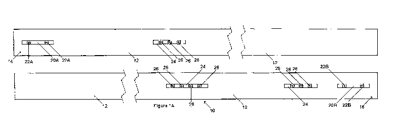
[00029] Referring now to Figures 1A and 1B, diagrammatic side and end
views,
respectively, of a tubular shaft (10) usable within the scope of the present
disclosure are shown. The tubular shaft (10) includes a generally cylindrical
body (12) having a first end (14), a second end (16) and a longitudinal cavity
(18)
extending between the ends (14, 16). In a preferred embodiment, the tubular
shaft (10) can be formed from titanium, though it should be understood that
any
generally lightweight, high strength material having a generally low modulus
of
elasticity can be used to form the tubular shaft (10) without departing from
the
scope of the present disclosure. The depicted tubular shaft (10) is shown
having
a constant wall thickness (Ti) throughout its length; however, in various
embodiments, the inner or outer surfaces of the shaft (10) could be provided
with
protrusions, shoulders, tapers, and/or regions of greater or lesser thickness
to
provide increased or decreased weight and/or flexibility/stiffness to various
portions of the shaft (10). However, an advantage of the embodied modular
systems, assemblies, and methods described herein, and an advantage of the use
of low modulus materials to form the tubular shaft (10) is the ability to
utilize a
generally straight shaft having a constant wall thickness, which facilitates
manufacture and reduces cost.
[00030] The depicted tubular shaft (10) includes a first connection region
(20A)
proximate to the first end (14), which can include one or more pins (22A)
extending therefrom (e.g., into the longitudinal cavity (18)). Similarly, a
second
connection region (20B) is shown proximate to the second end (16) having pins
7
CA 02892186 2015-05-20
WO 2014/081445
PCT/US2013/000229
(22B) extending therefrom. The pins (22A, 22B) can be engaged within
corresponding orifices of modular inserts, as described above and below. It
should be understood that the depicted configuration is merely exemplary, and
that in other embodiments, the tubular shaft (10) could include orifices
within
which pins extending from the outer surface of inserts can be engaged.
Alternatively and/or additionally, inserts could be retained within the
tubular
shaft (10) via a friction fit or similar methods, such that a mechanical
connection
utilizing pins and orifices is not necessary.
[00031] The tubular shaft (10) is further shown having three additional
connecting regions
(24) from which pins (26) can extend, the additional connecting regions (24)
being usable to engage additional orifices within inserts to provide a more
secure
connection, or alternatively, to engage the tubular shaft (10) to other
portions of a
vehicle. For example, the depicted tubular shaft (10) could be used as part of
a
rear axle of a go-kart, while one or more of the additional connecting regions
(24)
are used to engage the rear axle to other portions of the go-kart frame.
[00032] While tubular shafts usable within the scope of the present
disclosure can have
any shape, dimensions, and/or materials, depending on the characteristics of
the
vehicle with which the tubular shaft (10) is used, the purpose for which the
vehicle and/orshaft (10) is used, and other similar factors, the depicted
tubular
shaft (10) is formed from titanium, having a length of about 40.19 inches, an
outer diameter of about 1.916 inches, and an inner diameter of about 1.790
inches
(a wall thickness of 0.179 inches.) The position of the connecting regions
(20A,
20B, 24) and pins (22A, 22B, 26) can vary depending on the location of
corresponding orifices and/or similar features on inserts intended for use
with the
shaft (10) and/or the position, dimensions, and/or other characteristics of
other
portions of the vehicle to which the shaft (10) is to be engaged.
[00033] Figures 2A and 2B depict an embodiment of an insert (28) usable
within the
scope of the present disclosure. Specifically, Figure 2A depicts an end view
of
the insert (28), while Figure 2B depicts a partial cross-sectional view
thereof,
taken along line B of Figure 2A. As described above, the depicted insert (28)
can
be positioned within the longitudinal cavity (18, shown in Figures IA and 1B)
of
the tubular shaft (10, shown in Figures IA and 1B) (e.g., at an end thereof)
to
8
CA 02892186 2015-05-20
WO 2014/081445
PCT/US2013/000229
provide at least a portion of the shaft with an effective wall thickness
greater than
the thickness of the tubular shaft alone, and to provide a portion of the
shaft with
a selected weight and flexibility/stiffness, determined by the dimensions and
material characteristics of the insert (28).
[00034] The depicted insert (28) includes a generally cylindrical body (30)
having a
longitudinal cavity (32) and a tapered shoulder (34) (e.g., a 45 degree
shoulder) at
an end thereof to facilitate insertion and/or removal of the insert (28) from
the
tubular shaft. In a preferred embodiment, the insert (28) can be formed from
aluminum, though it should be understood that any generally durable material
able to hold its shape and provide the axle shaft assembly with an effective
wall
thickness can be used, including, without limitation, steel, wood, composite,
and/or other metals, alloys, and/or polymers. The depicted insert (28) is
shown
having a length (L) and a generally constant wall thickness (T2) throughout
its
length; however, in various embodiments, the inner or outer surfaces of the
insert
(28) could be provided with protrusions, shoulders, tapers, and/or regions of
greater or lesser thickness to provide increased or decreased weight and/or
flexibility/stiffness to various portions thereof. In use, when the insert
(28) is
placed within a tubular shaft, the total thickness of the assembly (e.g., the
thickness of the tubular shaft plus the thickness of the insert) creates an
overall
thickness for a portion of the assembly, which, in combination with the
material
characteristics of the shaft and insert, provides a desired weight, stiffness,
and/or
suspension characteristic to at least a portion of the resulting axle
assembly.
[00035] Within the body (30) of the insert (28), a series of five orifices
(36A, 36B, 36C,
36D, 36E) are shown, each of which can engage a corresponding pin within the
tubular shaft (10, shown in Figures IA and 1B) to secure the insert (28)
therein.
For example, the depicted orifices are positioned such that the first and
second
orifices (36A, 36B) can be engaged by pins (22A, 22B, shown in Figure 1A)
within the first engagement region (20A, shown in Figure 1A), while the third,
fourth, and fifth orifices (36C, 36D, 36E) can be engaged by pins (26, shown
in
Figure 1A) within the additional engagement region (24, shown in Figure IA)
closest to the first engagement region. As described previously, however, use
of
a pin-in-hole arrangement is merely one, non-limiting method by which the
insert
9
CA 02892186 2015-05-20
WO 2014/081445
PCT/US2013/000229
(28) can be secured in a desired position, and any other means known in the
art
can be used without departing from the scope of the present disclosure.
Further,
while five orifices (36A, 36B, 36C, 36D, 36E) are shown, it should be
understood
that any number and configuration of protrusions and/or orifices can be used.
[00036] The body (30) of the insert (28) is shown having a small gap (38)
within the
circumference thereof, which is usable to enable insertion of the insert (28)
within the longitudinal cavity (18, shown in Figures IA and 1B) of the tubular
shaft (10, shown in Figures IA and 1B). For example, the presence of the gap
(38) allows the insert (28) to be compressed (e.g., such that the ends of the
body
(30) on opposite ends of the gap (38) contact one another), thereby
temporarily
decreasing the diameter of the insert (28). The compressed insert can then be
inserted into a longitudinal cavity, engaged with pins therein, and allowed to
expand, such that the outer surface of the insert (28) contacts the inner
surface of
the shaft into which the insert (28) is positioned, further securing the
insert (28)
in place.
[00037] While inserts usable within the scope of the present disclosure can
have any
shape, dimensions, and/or materials, depending on the characteristics of the
vehicle and axle assembly with which the insert (28) is used, the purpose for
which the vehicle and/or axle assembly is used, and other similar factors, the
depicted insert (28) is formed from aluminum, having a length of about 9.1
inches, an outer diameter of about 1.835 inches, and an inner diameter of
about
1.556 inches (a wall thickness of 0.279 inches.) The position of the orifices
(36A, 36B, 36C, 36D, 36E) can vary depending on the location of corresponding
pins and/or similar features on the tubular shaft intended for use with the
insert
(28). The gap (38) can be generally narrow in width, occupying approximately 6
degrees (1.66 percent) of the circumference of the insert (28).
[00038] Figures 3A and 3B depict an alternate embodiment of an insert (40)
usable within
the scope of the present disclosure. Specifically, Figure 3A depicts an end
view
of the insert (40), while Figure 3B depicts a partial cross-sectional view
thereof
taken along line B of Figure 3A. The depicted insert (40) and the insert (28,
shown in Figures 2A and 2B) of Figures 2A and 2B can each be removably and
interchangeably positioned within the tubular shaft (10, shown in Figures IA
and
CA 02892186 2015-05-20
WO 2014/081445
PCT/US2013/000229
1B) of Figures IA and 1B, as described above and below.
[00039] The depicted insert (40) includes a generally cylindrical body (42)
having a
longitudinal cavity (44) and a tapered shoulder (46) at an end thereof. In
a
preferred embodiment, the insert (40) can be formed from aluminum, though it
should be understood that any generally durable material, as described above,
can
be used, including a similar or different material than that used to form the
insert
of Figures 2A and 2B. The insert (40) is shown having a length (L) generally
equal to that of the insert of Figures 2A and 2B, though in an embodiment,
interchangeable inserts can be provided with differing lengths, such as when
it is
desirable to configure differing lengths of an axle shaft to have selected
stiffnesses and/or suspension characteristics. The insert (40) is further
shown
having a generally constant wall thickness (T3), less than the thickness (T2,
shown in Figure 2B) of the insert of Figures 2A and 2B. In use, when the
insert
(40) is placed within a tubular shaft, the total thickness of the axle
assembly (e.g.,
the thickness of the tubular shaft plus the thickness of the insert) creates
an
overall thickness for a portion of the assembly, which, in combination with
the
material characteristics of the shaft and insert, provides a desired weight,
stiffness, and/or suspension characteristic to at least a portion of the
resulting axle
assembly.
[00040] The body (42) of the depicted insert (40) includes two orifices
(48A, 48B)
formed therein, the orifices being usable for engagement with corresponding
pins
in the tubular shaft (10, shown in Figures 1A and 1B). For example, the
orifices
(48A, 48B) can each accommodate pins (22B, shown in Figure 1A) extending
from the second engagement region (20B). While Figure 3B depicts the insert
(40) having only two orifices (48A, 48B), it should be understood that any
number and configuration or protrusions and/or orifices can be used, and/or
any
other means of engagement between the insert (40) and a tubular shaft, as
described previously. A small gap (49) within the circumference of the body
(42)
of the insert (40) is shown, which can be used to enable insertion of the
insert
(40) within a tubular shaft in a manner similar to that described above with
regard
to the insert of Figures 2A and 2B.
[00041] While inserts usable within the scope of the present disclosure can
have any
11
CA 02892186 2015-05-20
WO 2014/081445
PCT/US2013/000229
shape, dimensions, and/or materials, depending on the characteristics of the
vehicle and axle assembly with which the insert (40) is used, the purpose for
which the vehicle and/or axle assembly is used, and other similar factors, the
depicted insert (40) is formed from aluminum, having a length of about 9.0
inches, an outer diameter of about 1.826 inches, and an inner diameter of
about
1.740 inches (a wall thickness of 0.086 inches.) The position of the orifices
(48A, 48B) can vary depending on the location of corresponding pins and/or
similar features on the tubular shaft intended for use with the insert (40).
The gap
(49) can be generally narrow in width, occupying approximately 6 degrees (1.66
percent) of the circumference of the insert (28).
[00042] Figures 4A and 4B depict diagrammatic side and end views,
respectively, of an
axle assembly usable within the scope of the present disclosure. The tubular
shaft (10), having an elongate, generally cylindrical body (12) is shown,
defining
a longitudinal cavity therein. The body (12) of the depicted tubular shaft
(10) has
a generally thin and constant wall thickness (T1).
[00043] A first insert (28A) having a generally cylindrical body (30A) is
shown inserted
into a first end of the tubular shaft (10), the first insert (28A) having a
selected
length (L) and a wall thickness (T2). Similarly, a second insert (28B) having
a
generally cylindrical body (30B) is shown inserted into the opposing end of
the
tubular shaft (10), the second insert (28B) having a length (L) and wall
thickness
(T2) substantially equal to that of the first insert (28A). Figure 4A depicts
the
first and second inserts (28A, 28B) having substantially identical dimensions
and
configurations; however, it should be understood that in various embodiments,
two inserts having differing dimensions, positions, and/or material
characteristics
could be used.
[00044] The overlap between the first insert (28A) and the first end
portion of the tubular
shaft (10) defines a first end region (50A) of the axle shaft assembly, while
the
overlap between the second insert (28B) and the second end portion of the
tubular
shaft (10) defines a second end region (50B). The end regions have an
effective
wall thickness (T3) created by the overlapping wall thicknesses (T1, T2) of
the
shaft (10) and inserts (28A, 28B) (e.g., the sum of Ti and T2 is substantially
equal to T3). The position of the inserts (28A, 28B) within the shaft (10)
defines
12
CA 02892186 2015-05-20
WO 2014/081445
PCT/US2013/000229
a central portion (52) of the axle shaft assembly unoccupied by the inserts
(28A,
28B) due to the limited lengths (L) thereof. As such, in use, the central
portion
(52) provides the axle shaft assembly with a desirable flexibility, strength,
and
resiliency due to the limited thickness (Ti) of the wall thereof, and due to
the low
modulus of elasticity of the material used (e.g., titanium). The end portions
(50A, 50B) (e.g., the portions of the axle shaft that would generally be
positioned
over and/or in association with the wheels of a go-kart or similar vehicle)
provide
desirable portions of the axle shaft assembly with a selected stiffness,
weight, and
suspension characteristic, determined by the thickness (T3) of the end
portions
(50A, 50B) and the material characteristics of the shaft (10) and inserts
(28A,
28B). When desired, the inserts (28A, 28B) can be removed and replaced with
alternate inserts, having a differing wall thickness, material, and/or length,
to
provide alternate characteristics to the axle shaft.
[00045] As such, embodiments usable within the scope of the present
disclosure enable a
single axle shaft (e.g., a titanium shaft having a generally thin, uniform
wall
thickness) to be provided with multiple suspension characteristics (e.g.,
variable
flexibility, weight, stiffness, and/or thickness), through the provision of
inserts
having selected wall thicknesses, materials, and/or lengths, thereby enabling
the
axle shaft to be adapted for multiple types of track and racing conditions.
Use of
an axle shaft assembly that incorporates lightweight, high strength materials,
including materials having a lower modulus of elasticity than conventional
steel
alloys, enables the axle shaft to withstand side impacts without deformation
and
provide desirable suspension characteristics, while also providing an assembly
that is significantly lighter than conventional alternatives, and is thus able
to be
rotated and accelerated more rapidly than conventional axles without adding
significant weight to a vehicle, enabling a higher overall speed for the
vehicle.
Further, use of an axle shaft assembly that incorporates interchangeable,
modular
components enables a single tubular shaft with corresponding inserts to
replace a
conventional set of multiple steel shafts.
[00046] While various embodiments usable within the scope of the present
disclosure
have been described with emphasis, it should be understood that within the
scope
of the appended claims, the present invention can be practiced other than as
13
CA 02892186 2015-05-20
WO 2014/081445
PCT/US2013/000229
specifically described herein.
14