Note : Les descriptions sont présentées dans la langue officielle dans laquelle elles ont été soumises.
CA 02892409 2016-12-01
A METHOD FOR ARRANGING ROLLING-FRICTION EXTENDING AND
RETRACTION BASED ROLLING STROKE SECTION OF A ROCKER ARM IN
PARALLEL, AND AN EXCAVATOR OR LOADER COMPRISING A ROCKER ARM
HAVING ROLLING STROKE SECTIONS IN PARALLEL
Technical field
The present invention relates to the field of excavators or loaders, and in
particular, to a
method for arranging rolling-friction extending and retraction based rolling
stroke sections of a
rocker arm in parallel, and an excavator or loader comprising a rocker arm
having rolling stroke
sections arranged in parallel.
Background
The rocker arms of commonly used equipment such as heading machines or coal
mining
machines or loading machines, for example, the rocker arms of reciprocating
impact heading
machines or the rocker arms of reciprocating impact coal mining machines or
the rolling harrow
support rocker arms of rolling-harrow loading machines, all extend and retract
relative to the
machine bodies by means of sliding friction, resulting in high sliding
friction resistance and
strong twisting force. In order to improve work efficiency and applicability,
the work heads of
the heading machine, the coal mining machine, the loading machine and the like
are designed to
have large volume and great weight. The work heads having large volume and
great height
produce great twisting gravity and serious reciprocating wear onto the
telescopic sliding guide
rail; moreover, in operation, crawling jitters are easy to occur, and in
serious cases, bonding burn
may appear in the sliding friction surface. The most critical thing is that
the adjustment to the
movement fails because it is difficult to form a uniform lubricating oil film
on the friction
surface thereof to generate heat by friction owing to the particularity of
working environment. In
order to avoid extending/retracting and sliding friction faults of the rocker
arms, many
manufacturers do not use telescopic rocker arms. However, service efficiency
and adaptability
are seriously reduced by forbidding the rocker arm to extend or retract
relative to the machine
body. In some cases, the slide rail is shortened in order to reduce sliding
frictional resistance, but
this would result in problems such as short rocker arm extending/retracting
distance, small
CA 02892409 2016-12-01
excavation or loading range, bad adaptability, and low operating efficiency,
etc. Furthermore, the
service efficiency and adaptability will be more seriously reduced if the
rocker arm is forbidden
to extend or retract relative to the machine body. In order to solve the above
problems, rolling
friction is used in the present invention to reduce wear and frictional
resistance, and more
especially, the rolling stroke sections of the rollers are arranged in
parallel. Therefore, the present
invention provides a method for arranging rolling-friction extending and
retraction based rolling
stroke sections of a rocker arm in parallel, and an excavator or loader
comprising a rocker arm
having rolling stroke sections arranged in parallel.
Summary of the invention
The present invention is realized by adopting the following technical
solution: the excavator
or loader comprising a rocker arm having rolling stroke sections arranged in
parallel comprises a
rocker arm, a machine body, a work head, etc.; the rocker arm comprises a
front roller, a rear
roller, a front roller raceway, a rear roller raceway, a telescopic arm, and a
telescopic support arm,
etc.; the front roller raceway is disposed on the telescopic arm or the
telescopic support arm, or
the like; the rear roller raceway is disposed on the telescopic support arm or
the telescopic arm or
the machine body or the like; the front roller is disposed on the telescopic
support arm or the
telescopic arm or the like; the rear roller is disposed on the telescopic arm
or the telescopic
support arm or the like; the front roller raceway and the rear roller raceway
are arranged in
parallel; the front roller rolls within the front roller raceway; the rear
roller rolls within the rear
roller raceway; the front roller coordinates with the rear roller to support
the telescopic arm to
perform rolling-friction extending and retraction on the telescopic support
arm by means of
rolling friction; the work head is connected with the telescopic arm which
drives the work head
to extend and retract; and the telescopic support arm is connected with the
machine body.
The present invention further comprises the following method for arranging
rolling-friction
extending and retraction based rolling stroke sections of a rocker arm in
parallel, which is
specifically as follows.
Method 1:
Step 1: providing a front roller, a rear roller, a front roller raceway, a
rear roller raceway, a
telescopic arm, a telescopic support arm, etc.; disposing the front roller
raceway on the telescopic
arm or the telescopic support arm or the like; disposing the rear roller
raceway on the telescopic
2
CA 02892409 2016-12-01
support arm or the telescopic arm or the machine body or the like; disposing
the front roller on
the telescopic support arm or the telescopic arm or the like; disposing the
rear roller on the
telescopic arm or the telescopic support arm or the like; arranging the front
roller raceway and
the rear roller raceway in parallel; rolling the front roller within the front
roller raceway; rolling
the rear roller within the rear roller raceway; and coordinating the front
roller with the rear roller
to support the telescopic arm to perform rolling-friction extending and
retraction on the
telescopic support arm by means of rolling friction.
Step 2: providing a work head, and connecting the work head with the
telescopic arm so
that the telescopic arm drives the work head to extend and retract.
Step 3: connecting the telescopic support arm with a machine body, and
providing a
traveling gear on the lower part of the machine body so that the traveling
gear drives the machine
body to travel.
Method 2:
Configuring a front roller as a fixed wheel; configuring a rear roller as a
traveling wheel;
configuring a front roller raceway as a fixed wheel raceway; configuring a
rear roller raceway as
a traveling wheel raceway; arranging the fixed wheel raceway and the traveling
wheel raceway
in parallel; disposing the fixed wheel raceway along the direction of the
traveling wheel raceway,
and engaging the fixed wheel raceway onto the fixed wheel to partially or
completely overlap the
travelling wheel raceway and the fixed wheel raceway; and overlapping the
fixed wheel and
some or all of the rolling stroke sections of the traveling wheel, thereby
shortening a length
between the fixed wheel raceway and the traveling wheel raceway arranged one
behind the other,
reducing the length of the rocker arm under the condition of equal extending
and retracting
distances, and shortening the force arm of the work head that twists a machine
body.
The work head comprises a rolling harrow, or a reciprocating impact head, or a
bucket, or a
scraper box, or a cutting drum, or a crushing head, or a combination of a
reciprocating impact
head and a bucket, or a combination of a rolling harrow and a scraper box, or
a combination of a
rolling harrow with a reciprocating impact head, or the like.
The rocker arm comprises a rolling harrow rocker arm, or a reciprocating
impact head
rocker arm, or an excavation/loading rocker arm, or a combination of a rolling
harrow rocker
3
CA 02892409 2016-12-01
arm and a reciprocating impact head rocker arm, or a combination of a
reciprocating impact head
rocker arm and a scraper box rocker arm, or the like.
The front roller comprises a fixed wheel; the rear roller comprises a
traveling wheel; the
front roller raceway comprises a fixed wheel raceway; the rear roller raceway
comprises a
traveling wheel raceway; the fixed wheel raceway and the telescopic arm are
separately
connected or integrated; the traveling wheel raceway and the telescopic
support arm are
separately connected or integrated; the fixed wheel is disposed on the front
end of the telescopic
support arm and rolls within the fixed wheel raceway; the traveling wheel
rolls within the
traveling wheel raceway and is fixed to the back of the telescopic arm; the
fixed wheel raceway
and the traveling wheel raceway are arranged in parallel; and the fixed wheel
overlaps some or
all of the rolling stroke sections of the traveling wheel, thereby shortening
a length between the
fixed wheel raceway and the traveling wheel raceway arranged one behind the
other, reducing
the length of the rocker arm under equal extending and retracting distances,
reducing the total
height of the rocker arm, and shortening a force arm that damages the machine
body through
twisting.
The fixed wheel raceway comprises a fixed wheel groove; the telescopic arm
comprises a
rolling harrow telescopic arm; the retractable support arm comprises a rolling
harrow telescopic
support arm; the fixed wheel groove and the rolling harrow telescopic arm are
separately
connected and integrated; the traveling wheel raceway is disposed on the
telescopic support arm;
the rear roller comprises a slide opening roller; the traveling wheel raceway
comprises a slide
opening roller groove; the slide opening roller rolls within the slide opening
roller groove and is
fixed to the back of the rolling harrow telescopic arm; the fixed wheel groove
and the slide
opening roller groove are arranged in parallel; when the rolling harrow
telescopic arm is lifted up
by bulk materials, the fixed wheel groove hoists the fixed wheel to pull up
the rolling harrow
telescopic support arm; the slide opening roller and fixed wheel support and
pull the rolling
harrow telescopic arm to extend/retract and ascend/descend.
The outer surface of the rear roller is provided with a convex surface or a
concave surface;
if the outer surface of the rear roller is provided with a concave surface,
the rear roller raceway is
correspondingly provided with a convex surface engaged to the concave surface
of the rear roller
to conduct rolling guide for the telescopic arm; and if the outer surface of
the rear roller is
4
CA 02892409 2016-12-01
provided with a convex surface, the rear roller raceway is correspondingly
provided with a
concave surface engaged to the convex surface of the rear roller to conduct
rolling guide for the
telescopic arm.
The front roller and rear roller are arranged between the telescopic arm and
telescopic
.. support arm to form a rolling guide device; the rolling guide device
comprises a protector for
preventing mud, water, dust, or material or the like from entering the rolling
guide device. The
protector and the fixed wheel roller groove are separately engaged or
integrated.
The front roller rollaway comprises a U-shaped raceway or a square raceway or
a circular
raceway or a C-shaped raceway or a [-shaped raceway or an H-shaped raceway or
the like.
The rocker arm is hingedly connected with a machine body via a rotary limiting
hinge shaft
or is connected with the machine body via a rotary structure; a rotation-
stopping limiting
structure is disposed at the hinge joint and rotary joint of the rocker arm
and the machine body;
the rotation-stopping limiting structure comprises a rotary limiting platform,
a machine body
rotation stopping platform, and the like; the rotary limiting platform rotates
about the rotary
.. structure or the limiting hinge shaft; when the rotary limiting platform
rotates to an angle where
the telescopic support arm and the work head are about to be in collision with
a shovel plate, the
machine body rotation stopping platform is pressed against the rotary limiting
platform, so that
the machine body rotation stopping platform stops the rotary limiting platform
from continuing
rotating; the rocker arm is limited to continue descending by limiting the
rotation angle thereof, a
reasonable safety gap is maintained between each of the rocker arm and the
work head and the
shovel plate.
The machine body comprises a shovel plate frame, a machine body frame, a
shovel plate
controllers, and the like; the shovel plate frame is hingedly connected with
the machine body
frame or the shovel plate frame is connected with the machine body frame via a
rotary structure;
one end of the shovel plate controller is disposed on the machine body frame,
and the other end
is disposed on the shovel plate frame; the shovel plate controller drives the
shovel plate to
ascend/descend in the way of unidirectional rotation or multidirectional
rotation.
The machine body and/or the rocker arm comprises a discharging stopping
device; the
discharging stopping device comprises a plate type discharging device or a
fork type discharging
device or a brush type discharging device or a tooth-type discharging device,
or the like.
5
CA 02892409 2016-12-01
The front roller comprises a pin roller or a waist drum wheel or a multi-
directional wheel or
the like.
The rear roller comprises an alloy steel roller or an ordinary steel roller or
a polymer roller
or a rubber roller or a ceramic roller or the like.
The shovel plate controller is disposed on the upper part of the machine body;
the machine
body comprises a shovel plate controller support; one end of the shovel plate
controller is
hingedly connected to the shovel plate controller support or is connected with
the shovel plate
controller support via a rotary structure, and the other end is connected with
the shovel plate
frame; the joint of the shovel plate frame and the machine body frame is
disposed on the lower
part of the machine body; a distance from the shovel plate controller support
on the upper part of
the machine body to the force arm at the joint of the shovel plate frame and
the machine body
frame is greater than a distance, in the event that the shovel plate
controller is disposed on the
lower part of the machine body, from the shovel plate controller support to
the force arm at the
joint of the shovel plate frame and the machine body frame; the shovel plate
controller drives the
shovel plate frame which drives the shovel plate to ascent/descend, thereby
reducing power
consumption and the number of the shovel plate controllers.
The rear roller rollaway comprises an anti-swing roller groove; the rear
roller comprises an
anti-swing roller; the anti-swing roller groove and the machine body are
separately or fixedly
connected; the anti-swing roller performs linear reciprocating rolling in the
anti-swing roller
groove to support the rolling-friction extending and retraction of the
telescopic arm; the
telescopic arm is limited to swing from side to side by the anti-swing roller.
The rear roller rollaway comprises an anti-swing roller groove; the front
roller rollaway
comprises an ascending/descending roller groove; the anti-swing roller groove
and the
ascending/descending roller groove are arranged separately in parallel or are
arranged into one
piece; the front roller is an ascending/descending roller; the rear roller is
an anti-swing roller; the
ascending/descending roller rolls within the ascending/descending roller
groove; the anti-swing
roller rolls within the anti-swing roller groove; the rocker arm is hingedly
connected with the
machine body or is connected to the machine body via the rotary structure; the
telescopic arm is
limited to swing non-directionally from side to side by the anti-swing roller
and the telescopic
support arm is driven to ascend/descend by the ascending/descending roller, to
reduce a height
6
CA 02892409 2016-12-01
between the anti-swing roller groove and the ascending/descending roller
groove arranged one
below the other, as well as the total height of the rocker arm; the
ascending/descending roller
and/or the ascending/descending roller groove guides the rocker arm.
The rotation-stopping limiting structure enables the rocker arm to form a tilt
angle relative
to the ground; the tilt angle enables the work head not to be in collision
with the shovel plate;
owing to the tilt angle, the rocker arm enables the work head to be lower than
the shovel plate
when extending out of the upper part of the shovel plate and to excavate,
mill, load or crush
materials in the front of the shovel plate.
The machine body comprises a shovel plate frame; a shovel platform frame
limiting gantry
is disposed on the shovel plate frame at the lower part of the rocker arm; the
shovel platform
frame limiting gantry lifts up the telescopic support arm when the rocker and
the work head
descend to be about to collide with the shovel plate, thereby preventing the
rocker arm and the
work head from descending to be in collision with the shovel.
A buffer is disposed on the shovel platform frame limiting gantry; the buffer
absorbs the
impact caused by the rocker arm during descending.
The buffer comprises a rubber buffer cushion or a spring buffer cushion or a
polyurethane
buffer cushion or a nylon buffer cushion or a polymeric material buffer
cushion or the like.
The work head comprises a rolling harrow which comprises harrow teeth, a tooth
cylinder,
and the like; the length from the tip of each harrow tooth to the center line
of the tooth cylinder is
greater than the radius of the tooth cylinder.
The harrow teeth are shovel heads or pick heads or ivory teeth or hammers or
axes or hoes
or a combination or multiple shapes or the like.
The rotary structure comprises a ball-head ball-groove type, an arc-shaped
catching groove
type, a flexible universal joint coupling head, a universal joint bearing
coupling head, a universal
coupler coupling head, a joint bearing coupling head or a spherical hinge
mechanism, or the like.
The machine body comprises a rotary disk which comprises a rotary inner disk,
a rotary
outer disk, etc.; the rotary inner disk and the rotary outer disk rotates
relatively; when the rotary
inner disk is fixed on the machine body, the rotary outer disk rotates
relative to the rotary inner
disk; when the rotary outer disk is fixed on the machine body, the rotary
inner disk rotates
7
CA 02892409 2016-12-01
relative to the rotary outer disk; one end of the rocker arm is connected to
the rotary inner disk
under rotation or the rotary outer disk under rotation; the machine body
comprises a rotary disk
rotation controller which drives the rotary inner disk to rotate or the rotary
outer disk to rotate;
one end of the telescopic arm controller is connected with the rotary inner
disk under rotation or
the rotary outer disk under rotation, and the other end is connected with the
telescopic arm; the
rocker arm rotates with the rotary disk, to expand the excavation and/or
loading range.
The rocker arm or the machine body comprises a side-to-side movement
controller; the
telescopic arm comprises a telescopic section and a support work head section;
the telescopic
section is hingedly connected with the support work head section; a hinge
shaped is disposed
1 0
perpendicularly to the ground; one end of a extending and retraction
controller is connected with
the machine body via a rotary structure or is connected with the telescopic
support arm, and the
other end is connected with the telescopic section; one end of the side-to-
side movement
controller is connected with the machine body via a rotary structure or is
connected with the
telescopic support arm or the telescopic section, and the other end is
connected with support head
section; the side-to-side movement controller drives the support work head
section to move from
side to side; and the side-to-side movement controller drives the support work
head section to
move from side to side.
The rocker arm and/or the machine body comprises a rolling harrow driving
device; the
rolling harrow comprises harrow teeth, a tooth cylinder, etc.; the rolling
harrow driving device
comprises an electrical machine or a motor or the like; the electrical machine
or motor or the like
is disposed inside or outside the tooth cylinder.
The rolling harrow driving device comprises a transmission which comprises a
gear
transmission or a belt transmission or a sprocket transmission or a rope
sheave transmission or
the like.
The front roller comprises a fixed wheel felly and a fixed wheel shaft; the
fixed wheel felly
and the fixed wheel shaft are connected separately or integrated.
The telescopic support arm is hingedly connected with the machine body or is
connected
with the machine body via a rotary structure or is fixedly connected with the
machine body.
The rotary disk rotation controller comprises a telescopic oil cylinder, or a
gear and a rack,
8
CA 02892409 2016-12-01
or a rope and a rope winder, or a telescopic air cylinder, or a sprocket and a
chain, or the like.
The machine body comprises a rocker arm ascending/descending controller which
controls
the rocker arm to ascend and descend; the ascending/descending controller
comprises an
ascending/descending oil cylinder, or a gear and a rack, or a rope and a rope
winder, or an
ascending/descending air cylinder, or a sprocket and a chain, or the like.
The rotary disk comprises a multilayer rotary disk which comprise a lower-
layer rotary disk,
an upper-layer rotary disk, and the like.
A rolling harrow rocker arm is provided on the lower-layer rotary disk; a
reciprocating
impact head rocker arm is provided on the upper-layer rotary disk; the lower-
layer rotary disk
drives the rolling harrow rocker arm to rotate horizontally and/or vertically;
the upper-layer
rotary disk drives the reciprocating impact head rocker arm to rotate
horizontally and/or
vertically; the rolling harrow rocker arm coordinates with the reciprocating
impact head rocker
arm to excavate and load materials in multiple azimuths and angles.
The present invention has the beneficial effects below:
The present invention provides a method for arranging rolling-friction
extending and
retraction based rolling stroke sections of a rocker arm in parallel, and an
excavator or loader
comprising a rocker arm having rolling stroke sections arranged in parallel,
which have the
following advantages:
1. For the rocker arm of an excavator or loader having rolling stroke sections
arranged in
parallel, the front roller raceway and the rear roller raceway are arranged in
parallel; the front
roller rolls within the front roller raceway; the rear roller rolls within the
rear roller raceway; and
the front roller coordinates with the rear roller to support the rocker arm to
extend and retract by
means of rolling friction, to improve moving efficiency and flexibility of the
rocker arm in
adapting to excavating and/or loading various materials, and expand the
excavating and/or
loading range, thereby enabling the rocker arm to flexibly excavate and/or
load materials, etc.
2. The fixed wheel raceway and the traveling wheel raceway are arranged in
parallel; and
the fixed wheel overlaps some or all of the rolling stroke sections of the
traveling wheel, to
shorten the length between the fixed wheel raceway and the traveling wheel
raceway arranged
one behind the other, reduce the length of the rocker arm under equal
extending and retracting
9
CA 02892409 2016-12-01
distances, decrease the total height of the rocker arm, and shorten a force
arm that damages the
machine body through twisting, thereby reducing the use of raw materials, and
making the whole
machine more reasonable and compact in design and more safe, reliable and
flexible in
operation.
3. The slide opening roller rolls within a slide opening roller groove; the
slide opening roller
is fixed to the back of the rolling harrow telescopic arm; the fixed wheel
groove and the slide
opening roller groove are arranged in parallel; when the rolling harrow
telescopic arm is lifted up
by bulk materials, the fixed wheel groove hoists the fixed wheel to pull up
the rolling harrow
telescopic support arm; the slide opening roller and the fixed wheel support
and pull the rolling
harrow telescopic arm to extend/retract and ascend/descend.
4. The outer surface of the front roller is provided with a concave surface or
a convex
surface; if the outer surface of the front roller is provided with a concave
surface, the front roller
raceway is correspondingly provided with a convex surface engaged to the
concave surface of
the front roller to conduct rolling guide for the telescopic arm; if the outer
surface of the front
roller is provided with a convex surface, the front roller raceway is
correspondingly provided
with a concave surface engaged to the convex surface of the front roller to
conduct rolling guide
for the telescopic arm; the outer surface of the rear roller is provided with
a concave surface or a
convex surface; if the outer surface of the rear roller is provided with a
convex surface, the rear
roller raceway is correspondingly provided with a convex surface engaged to
the concave surface
of the rear roller to conduct rolling guide for the telescopic arm; if the
outer surface of the rear
roller is provided with a convex surface, the rear roller raceway is
correspondingly provided with
a concave surface engaged to the convex surface of the rear roller to conduct
rolling guide for the
telescopic arm, so that the rollers roll within corresponding raceways,
thereby effectively
limiting the rolling directions of the rollers, and controlling the
extending/retracting direction of
the telescopic arm.
5. The rocker arm is hingedly connected with a machine body via a rotary
limiting hinge
shaft or is connected with the machine body via a rotary structure; a rotation-
stopping limiting
structure is disposed at the hinge joint and a rotary joint of the rocker arm
and the machine body;
the rotary limiting platform rotates about the rotary structure or rotates
about the limiting hinge
shaft; when the rotary limiting platform rotates to an angle where the
telescopic support arm and
CA 02892409 2016-12-01
the work head are about to be in collision with a shovel plate, the machine
body rotation stopping
platform is pressed against the rotary limiting platform, so that the machine
body rotation
stopping platform stops the rotary limiting platform from continuing rotating;
the rocker arm is
limited to continue descending by limiting the rotation angle thereof, a
reasonable safety gap is
maintained between each of the rocker arm and the work head and the shovel
plate.
6. When the rocker arm extends out of a position to separate the work head
from the upper
part of the shovel plate, the rear-end raceway of the front roller raceway
rotates about the front
roller to enable the work head to be lower than the shovel plate for
excavation and/or loading.
7. The shovel plate frame is hingedly connected with the machine body frame or
the shovel
plate frame is connected with the machine body frame via a rotary structure;
one end of a shovel
plate controller is disposed on the machine body frame, and the other end is
disposed on the
shovel plate frame; the shovel plate controller drives the shovel plate to
ascend/descend in the
way of unidirectional rotation or multidirectional rotation, thereby further
improving the
applicability of the excavator or loader to excavate and/or load materials at
differing heights.
8. The shovel plate controller drives the shovel plate connected with the
shovel plate frame
to move up and down and/or move from side to side; the shovel plate frame
drives the rocker
arm to move up and down and/or move from side to side synchronously with the
shovel plate,
thereby preventing the shovel plate from being locked or in collision with the
rocker arm and the
work head when the movements of the shovel plate or the rocker arm and the
work head are
controlled respectively.
9. The discharge stopping device avoids the fault that the rolling harrow
throws the
materials to the machine body and the console and the like when harrowing the
materials
quickly.
10. One end of the shovel plate controller is hingedly connected to the shovel
plate
controller support or is connected with the shovel plate controller support
via the rotary structure,
and the other end is connected with the shovel plate frame; the joint of the
shovel plate frame and
the machine body frame is disposed on the lower part of the machine body; a
distance from the
shovel plate controller support on the upper part of the machine body to the
force arm at the joint
of the shovel plate frame and the machine body frame is greater than a
distance, in the event that
the shovel plate controller is disposed on the lower part of the machine body,
from the shovel
i
CA 02892409 2016-12-01
plate controller support to the force arm at the joint of the shovel plate
frame and the machine
body frame, so that the force arm that pulls the shovel plate to ascend and
descend is lengthened;
the shovel plate controller drives the shovel plate frame which drives the
shovel plate to
ascent/descend, thereby reducing power consumption and the number of the
shovel plate
controllers.
11. The anti-swing roller groove and the machine body are separately or
fixedly connected;
the anti-swing roller on the telescopic arm is engaged to the anti-swing
roller groove to roll
therein; the anti-swing roller performs linear reciprocating rolling in the
anti-swing roller groove
to support the rolling-friction extending and retraction of the telescopic
arm; the telescopic arm is
limited to swing from side to side by the anti-swing roller, so that the
telescopic arm ascends and
descends more stably.
12. The ascending/descending roller groove is engaged to the anti-swing roller
groove; the
ascending/descending roller rolls within the ascending/descending roller
groove; the anti-swing
roller rolls within the anti-swing roller groove; the rocker arm is hingedly
connected with the
machine body or is connected with the machine body via the rotary structure;
the telescopic arm
is limited to swing non-directionally from side to side by the anti-swing
roller and the telescopic
support arm is driven to ascend/descend by the ascending/descending roller, to
reduce a height
between the anti-swing roller groove and the ascending/descending roller
groove arranged one
below the other, as well as the total height of the rocker arm; the anti-swing
roller also drives the
rocker arm to ascend/descend; the ascending/descending roller groove and/or
the anti-swing
roller groove guides the rocker arm; and the ascending/descending roller
coordinates with the
anti-swing roller, thereby enhancing the control over the rolling and
extending/retraction of the
rocker arm.
13. The rotation-stopping limiting structure enables the rocker arm to form an
tilt angle
relative to the ground; the tilt angle enables the work head not to be in
collision with the shovel
plate; owing to the tilt angle, the rocker arm enables the work head to be
lower than the shovel
plate when extending out of the upper part of the shovel plate and to
excavate, mill, load or crush
the materials in the front of the shovel plate.
14. A shovel plate frame limiting gantry is disposed on the shovel plate frame
at the lower
part of the rocker arm; the shovel platform frame limiting gantry lifts up the
telescopic support
12
CA 02892409 2016-12-01
arm when the rocker and the work head descend to be about to collide with the
shovel plate,
thereby preventing the rocker arm and the work head from descending to be in
collision with the
shovel.
15. The shovel plate frame limiting gantry is provided with a buffer, etc.;
the buffer absorbs
the impact caused by the rocker arm during descending, thereby decreasing the
impact damage
caused by the descending of the rocker arm to the shovel plate frame limiting
gantry, etc.,
thereby reducing impact noise and improving work environment.
16. The length from the tip of each harrow tooth to the center line of the
tooth cylinder is
greater than the radius of the tooth cylinder, so that the harrow teeth are
easier to harrow and
shift materials.
17. The harrow teeth are like shovel heads, etc., thereby bringing benefit to
harrowing the
materials of different grain sizes into a conveying device, and improving the
capability of the
rolling harrow for harrowing and shifting scattered materials.
18. One end of a telescopic arm controller is connected with the rotary inner
disk under
rotation or the rotary outer disk under rotation, and the other end is
connected with the telescopic
arm; and the rocker arm rotates along with the rotary disk, thereby expanding
the excavating
and/or loading range, and increasing the material excavating, harrowing and
loading efficiency.
19. The telescopic section is hingedly connected with the support work head
section; the
hinge shaft is disposed perpendicularly to the ground; one end of the
extending and retraction
controller is connected with the machine body via a rotary structure or is
connected with the
telescopic support arm, and the other end is connected with the telescopic
section; one end of the
side-to-side movement controller is connected with the machine body via a
rotary structure or is
connected with the telescopic support arm or is connected with the telescopic
section, and the
other end is connected with the support work head section; the side-to-side
movement controller
drives the support work head section to move left and right, and the side-to-
side movement
controller drives the support work head section to move from side to side.
20. An electrical machine or motor is disposed in the tooth cylinder, so that
the roller
harrow has a simple and compact structure, thereby bringing benefit to
protecting the electrical
machine or motor with the tooth cylinder.
13
CA 02892409 2016-12-01
21. The fixed wheel felly and the fixed wheel shaft are an integrated
structure having larger
strength and less maintenance.
22. The combination of a rolling harrow rocker arm and a reciprocating impact
head rocker
arm or the combination of a reciprocating impact head rocker arm and a scraper
box rocker arm
has a higher working efficiency than the rolling harrow rocker arm or the
reciprocating impact
head rocker arm or an excavation/loading rocker arm used alone.
23. The rotary disk is configured as a multilayer rotary disk which comprises
a lower-layer
rotary disk, an upper-layer rotary disk; the rolling harrow rocker arm is
disposed on the
lower-layer rotary disk; the reciprocating impact head rocker arm is disposed
on the upper-layer
rotary disk; the lower-layer rotary disk drives the rolling harrow rocker arm
to rotate vertically
and/or horizontally; the upper-layer rotary disk drives the reciprocating
impact head rocker arm
to rotate vertically and/or horizontally; and the rolling harrow rocker arm
coordinates with the
reciprocating impact head rocker arm excavation/loading to excavate and load
materials in
multiple azimuths and angles; the work heads on the multi-layer rotary disk
work simultaneously
to significantly improve the working efficiency of the apparatus in
comprehensive operations.
24. The front roller and the rear roller are arranged between the telescopic
arm and the
telescopic support arm to form a rolling guide device which is provided with a
protector; the
protector prevents mud, water, dust or material, or the like from entering the
rolling guide device,
such that the rolling guide device operates more reliably and stably.
Brief Description of the Drawings
FIG. 1 is a structural schematic diagram of an excavator or loader comprising
a rocker arm
having rolling stroke sections arranged in parallel in embodiment 1;
FIG. 2 is a structural schematic diagram of an excavator or loader comprising
a rocker arm
having rolling stroke sections arranged in parallel in embodiment 1;
FIG. 3 is a structural schematic diagram of a rocker arm of an excavator or
loader
comprising a rocker arm having rolling stroke sections arranged in parallel in
embodiment 1;
FIG. 4 is a front view of a reciprocating impact head of an excavator or
loader comprising a
rocker arm having rolling stroke sections arranged in parallel in embodiment
2;
FIG. 5 is a front view of a rolling harrow of an excavator or loader
comprising a rocker arm
14
CA 02892409 2016-12-01
having rolling stroke sections arranged in parallel in embodiment 2;
FIG. 6 is a structural schematic diagram of a rocker arm of an excavator or
loader
comprising a rocker arm having rolling stroke sections arranged in parallel in
embodiment 3;
FIG. 7 is a structural schematic diagram of a rocker arm of an excavator or
loader
comprising a rocker arm having rolling stroke sections arranged in parallel in
embodiment 3.
FIG. 8 is a structural schematic diagram of an excavator or loader comprising
a rocker arm
having rolling stroke sections arranged in parallel in embodiment 4.
FIG. 9 is a sectional view of A-A in FIG. 8 in embodiment 4;
FIG. 10 is another structural schematic diagram of an excavator or loader
comprising a
rocker arm having rolling stroke sections arranged in parallel in embodiment
5.
FIG. 11 is a sectional view of B-B in FIG. 10 in embodiment 5;
FIG. 12 is a structural schematic diagram of an excavator or loader comprising
a rocker arm
having rolling stroke sections arranged in parallel in embodiment 6;
FIG. 13 is a sectional view of A-A in FIG 12 in embodiment 6;
FIG. 14 is a front view of an excavator or loader comprising a rocker arm
having rolling
stroke sections arranged in parallel in embodiment 7;
FIG. 15 is a front view of an excavator or loader comprising a rocker arm
having rolling
stroke sections arranged in parallel in embodiment 8;
FIG. 16 is a schematic diagram of a discharge stopper of an excavator or
loader comprising
a rocker arm having rolling stroke sections arranged in parallel in embodiment
9;
FIG. 17 is a front view of an excavator or loader comprising a rocker arm
having rolling
stroke sections arranged in parallel in embodiment 10;
FIG. 18 is a structure diagram of an excavator or loader comprising a rocker
arm having
rolling stroke sections arranged in parallel in embodiment 11;
FIG. 19 is a structural schematic diagram of an excavator or loader comprising
a rocker arm
having rolling stroke sections arranged in parallel in embodiment 12.
FIG. 20 is a schematic view of a shovel plate frame limiting gantry of an
excavator or
CA 02892409 2016-12-01
loader comprising a rocker arm having rolling stroke sections arranged in
parallel in embodiment
13.
FIG. 21 a schematic view of a rolling harrow of an excavator or loader
comprising a rocker
arm having rolling stroke sections arranged in parallel in embodiment 14.
FIG. 22 is another schematic view of a rolling harrow of an excavator or
loader comprising
a rocker arm having rolling stroke sections arranged in parallel in embodiment
14.
FIG. 23 is a structural schematic diagram of a rotary disk of an excavator or
loader
comprising a rocker arm having rolling stroke sections arranged in parallel in
embodiment 15.
FIG. 24 is a structural schematic diagram of a rotary disk of an excavator or
loader
.. comprising a rocker arm having rolling stroke sections arranged in parallel
in embodiment 15.
FIG. 25 is a structural schematic diagram of an excavator or loader comprising
a rocker arm
having rolling stroke sections arranged in parallel in embodiment 16.
FIG. 26 is a schematic view of a multilayer rotary disk of an excavator or
loader comprising
a rocker arm having rolling stroke sections arranged in parallel in embodiment
17.
In the figures: 1, rocker arm; 2, machine body; 3, front roller; 4, rear
roller; 5, front roller
rollaway; 6, rear roller rollaway; 7, telescopic arm; 8, telescopic support
arm; 9, work head; 10,
reciprocating impact head; 11, rolling harrow; 12, rolling harrow rocker arm;
13, reciprocating
impact head rocker arm; 14, excavation/loading rocker arm; 15, fixed wheel;
16, traveling wheel;
17, fixed wheel raceway; 18, traveling wheel raceway; 19, fixed wheel groove;
20, rolling
harrow telescopic arm; 21, rolling harrow telescopic support arm; 22, slide
opening roller; 23,
slide opening roller groove; 24, concave surface; 25, convex surface; 26,
rolling guide device; 27,
protector; 28, fixed wheel felly; 29, fixed wheel shaft; 30, limiting hinge
shaft; 31,
rotation-stopping limiting structure; 32, rotary limiting platform; 33,
machine body rotation
stopping platform; 34, shovel plate; 35, rotary structure; 36, shovel plate
frame; 37, machine
body frame; 38, shovel plate controller; 39, discharging device; 40, shovel
plate controller
support; 41, anti-swing roller groove; 42, anti-swing roller; 43,
ascending/descending roller
groove; 44, ascending/descending roller; 45, shovel plate frame limiting
gantry; 46, buffer; 47,
harrow tooth; 48, tooth cylinder; 49, rolling harrow driving device; 50,
transmission; 51, rotary
disk; 52, rotary inner disk; 53, rotary outer disk; 54, rotary disk rotation
controller; 55õ
16
CA 02892409 2016-12-01
telescopic arm controller; 56, telescopic section; 57, support work head
section; 58,
extending/retraction controller; 59, hinge shaft; 60, side-to-side movement
controller; 61,
ascending/descending controller; 62, multilayer rotary disk; 63, lower-layer
rotary disk; 64,
upper-layer rotary disk; 65, hammer; 66, pick.
The present invention is further described below with reference to the
accompanying
drawings.
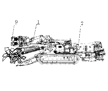
Embodiment 1
An excavator or loader comprising a rocker arm having rolling stroke sections
arranged in
parallel, as shown in FIGs. 1-3, is characterized in that: the excavator or
loader having rolling
stroke sections arranged in parallel comprises a rocker arm 1, a machine body
2, a work head 9,
etc.; the rocker arm 1 is mainly composed of a front roller 3, a rear roller
4, a front roller
rollaway 5, a rear roller rollaway 6, a telescopic arm 7, a telescopic support
arm 8, etc.; the front
roller rollaway 5 is disposed on the telescopic arm 7; the rear roller
rollaway 6 is disposed on the
telescopic support arm 8; the front roller 3 is disposed on the telescopic
support arm 8; the rear
roller 4 is disposed on the telescopic arm 7; the front roller rollaway 5 and
the rear roller
rollaway 6 are arranged in parallel; the front roller 3 rolls in the front
roller rollaway 5, and the
rear roller 4 rolls in the rear roller rollaway 6; the front roller 3
coordinates with the rear roller 4
to support the telescopic arm 7 to perform rolling-friction extending and
retraction on the
telescopic support arm 8 by means of rolling friction; the work head 9 is
connected with the
telescopic arm 7, so that the telescopic arm 7 drives the work head 9 to
extend and retract; the
telescopic support arm 8 is connected with the machine body 2; a traveling
device on the lower
part of the machine body drives the rocker arm and the work head to operate
continuously.
The front roller rollaway 5 may also be disposed on the telescopic support arm
8, etc.
The rear roller rollaway 6 may also be disposed on the telescopic arm 7 or the
machine
body 2 or the like.
The front roller 3 may also be disposed on the telescopic arm 7, etc.
The rear roller 4 may also be disposed on the telescopic support arm 8, etc.
The front roller 3 comprises a pin roller or a waist drum wheel or a multi-
directional roller
or the like.
17
CA 02892409 2016-12-01
The rear roller 4 is made of steel alloy or ordinary steel or high polymer
material or rubber
or ceramic or the like.
The telescopic support arm 8 is hingedly connected with the machine body 2 or
is
connected with the machine body 2 via a rotary structure or is fixedly
connected with the
.. machine body 2.
The front roller rollaway 5 a U-shaped raceway or a square raceway or a
circular raceway or
a C-shaped raceway or [-shaped raceway or an H-shaped raceway or the like.
The present invention provides a method for arranging rolling stroke sections
of a rocker
arm in parallel, which is specifically as follows:
Method 1:
Step 1: providing a front roller 3, a rear roller 4, a front roller raceway 5,
a rear roller
raceway 6, a telescopic arm 7, a telescopic support arm 8, etc.; disposing the
front roller raceway
5 on the telescopic arm 7 or the telescopic support arm 8; disposing the rear
roller raceway 6 on
the telescopic support arm 8 or the telescopic arm 7 or the machine body 2;
disposing the front
.. roller 3 on the telescopic support arm 8 or the telescopic arm 7; disposing
the rear roller 4 on the
telescopic arm 7 or the telescopic support arm 8; arranging the front roller
raceway 5 and the rear
roller raceway 6 in parallel; rolling the front roller 3 within the front
roller raceway 5; rolling the
rear roller 4 within the rear roller raceway 6; and coordinating the front
roller 3 with the rear
roller 4 to support the telescopic arm 7 to perform rolling-friction extending
and retraction on the
.. telescopic support arm 8 by means of rolling friction.
Step 2: providing a work head 9, and connecting the work head 9 with the
telescopic arm 7,
so that the telescopic arm 7 drives the work head 9 to extend and retract.
Step 3: connecting the telescopic support arm 8 with the machine body 2, and
disposing a
traveling device on the lower part of the machine body 2 so that the traveling
device drive the
machine body 2 to travel.
Method 2:
Configuring a front roller 3 as a fixed wheel 15; configuring a rear roller 4
as a traveling
wheel 16; configuring a front roller raceway 5 as a fixed wheel raceway 17;
configuring a rear
roller raceway 6 as a traveling wheel raceway 17 that is arranged in parallel
with the traveling
18
CA 02892409 2016-12-01
wheel raceway 18; disposing the fixed wheel raceway 17 along the direction of
the traveling
wheel raceway 18, and engaging the fixed wheel raceway 17 onto the fixed wheel
15 to partially
or completely overlap the travelling wheel raceway and the fixed wheel
raceway; and
overlapping the fixed wheel 15 and some or all of the rolling stroke sections
of the traveling
wheel 16, thereby shortening the length between the fixed wheel raceway 17 and
the traveling
wheel raceway 18 arranged one behind the other, reducing the length of the
rocker arm 1 under
the condition of equal extending and retracting distances, and shortening the
force arm of the
work head 9 that twists a machine body 2.
The others are the same as those in method 1.
Embodiment 2
As shown in FIG. 4 and FIG. 5, the excavator or loader comprising a rocker arm
having
rolling stroke sections arranged in parallel shown in embodiment 2 is
different from that in
embodiment 1 in that: the work head 9 comprises a rolling harrow 11, or a
reciprocating impact
head 10, or a bucket, or a scraper box, or a cutting drum, or a crushing head,
or a combination of
the reciprocating impact head 10 and the bucket, or a combination of the
rolling harrow 11 and
the scraper box, or a combination of the rolling harrow 11 and the
reciprocating impact head 10,
or the like.
The others are the same as those in embodiment 1.
Embodiment 3
As shown in FIG. 6 and FIG. 7, the excavator or loader comprising a rocker arm
having
rolling stroke sections arranged in parallel shown in embodiment 3 is
different from that in
embodiment 1 in that: the rocker arm 1 comprises a rolling harrow rocker arm
12, or a
reciprocating impact head rocker arm 13, or an excavating/loading rocker arm
14, or a
combination of the rolling harrow rocker arm 12 and the reciprocating impact
head rocker arm
12, or a combination of the reciprocating impact head rocker arm 13 and the
scraper box rocker
arm, or the like.
The others are the same as those in embodiment 1.
Embodiment 4
As shown in FIG. 8 and FIG. 9, the excavator or loader comprising a rocker arm
having
19
CA 02892409 2016-12-01
rolling stroke sections arranged in parallel shown in embodiment 4 is
different from that in
embodiment 1 in that the front roller 3 comprises a fixed wheel 15; the rear
roller 4 comprises a
traveling wheel 16; the front roller raceway 5 comprises a fixed wheel raceway
17; the rear roller
raceway 6 comprises a traveling wheel raceway 18; the fixed wheel raceway 17
is separately
connected with a telescopic arm 7; the traveling wheel raceway 18 is
separately connected with a
telescopic support arm 8; the front end of the telescopic support arm 8 is
provided with the fixed
wheel 15 that rolls within the fixed wheel raceway 17; the traveling wheel 16
rolls within the roll
wheel raceway 18 and is fixed to the back of the telescopic arm 7; the fixed
wheel raceway 17 is
arranged in parallel with the traveling wheel raceway 18; the fixed wheel 15
overlaps some or all
of the rolling stroke sections of the roll wheel 16, thereby shortening the
length between the
fixed wheel raceway 17 and the traveling wheel raceway 18 arranged on behind
the other,
decreasing the length of the rocker arm 1 under equal extending and retracting
distances,
reducing the total height of the rocker arm 1, and shortening the force that
twists and damages
the machine body 2.
The fixed wheel raceway 17 and the telescopic arm 7 may also be integrated.
The traveling wheel raceway 18 and the telescopic support arm 8 may also be
integrated.
The others are the same as those in embodiment 1.
Embodiment 5
As shown in FIGs. 10 and 11, the excavator or loader comprising a rocker arm
having
rolling stroke sections arranged in parallel shown in embodiment 5 is
different from that
embodiment 1 in that: the fixed wheel raceway 17 comprises a fixed wheel
groove 19; the
telescopic arm 7 comprises a rolling harrow telescopic arm 20; the telescopic
support arm 8
comprises a rolling harrow telescopic support arm 21; the fixed wheel groove
19 is separately
connected with the rolling harrow telescopic arm 20; a traveling wheel raceway
18 is provided
on the telescopic support arm 8; the rear roller 4 comprises a slide opening
roller 22; the
traveling wheel raceway 18 comprises a slide opening roller groove 23; the
slide opening roller
22 rolls within the slide opening roller groove 23; the slide opening roller
22 is fixed to the back
of the rolling harrow telescopic arm 20; the fixed wheel groove 19 is arranged
in parallel with
the slide opening roller groove 23; when the rolling harrow telescopic arm 20
is lifted up by bulk
materials, the fixed wheel groove 19 hoists the fixed wheel 15 to pull up the
rolling harrow
CA 02892409 2016-12-01
telescopic support arm 21; the slide opening roller 22 and the fixed wheel 15
support and pull the
rolling harrow telescopic arm 20 to extend/retract and ascend/descend.
The outer surface of the rear roller 4 is provided with a concave surface 24
and a convex
surface 25; if the outer surface of the rear roller 4 is provided with a
concave surface 24, the rear
roller raceway 6 is correspondingly provided with a convex surface 25 engaged
to the concave
surface 24 of the rear roller 4 to conduct rolling guide for the telescopic
arm 7; if the outer
surface 25 of the rear roller 4 is provided with a convex surface 25, the rear
roller raceway 6 is
correspondingly provided with a concave surface 24 engaged to the convex
surface 25 of the rear
roller 4 to conduct rolling guide for the telescopic arm 7.
The fixed wheel groove 19 and the rolling harrow telescopic arm 20 may also be
integrated.
The others are the same as those in embodiment 1.
Embodiment 6
As shown in FIG. 12 and FIG. 13, the excavator or loader comprising a rocker
arm having
rolling stroke sections arranged in parallel shown in embodiment 6 is
different from that in
embodiment 1 in that: the front roller 3 and the rear roller 4 are disposed
between the telescopic
arm 7 and the telescopic support arm 8 to form a rolling guide device 26 which
comprises a
protector 27 for preventing mud, water, dust or materials or the like from
entering the rolling
guide device 26.
The front roller 3 comprises a fixed wheel felly 28 and a fixed wheel shaft
29; the fixed
wheel felly 28 and the fixed wheel shaft 29 are separately connected.
The fixed wheel felly 28 and the fixed wheel shaft 29 may also be integrated.
The others are the same as those in embodiment 1.
Embodiment 7
As shown in FIG. 14, The excavator or loader comprising a rocker arm having
rolling
stroke sections arranged in parallel shown in embodiment 7 differs from that
in embodiment 1 in
that: the rocker arm 1 is hingedly connected with the machine body 2 via a
rotary limiting hinge
shaft 30, a rotation-stopping limiting structure 31 is disposed at the hinge
joint or rotary joint of
the rocker arm and the machine body; the rotation-stopping limiting structure
31 comprises a
21
CA 02892409 2016-12-01
rotary limiting platform 32, a machine body rotation stopping platform 33 and
the like; the rotary
limiting platform 32 rotates about the limiting hinge shaft 30; when the
rotary limiting platform
32 rotates to an angle where the telescopic support arm 8 and the work head 9
are about to be in
collision with a shovel plate 34, the machine body rotation stopping platform
33 is pressed
-- against the rotary limiting platform 32 so that the machine body rotation
stopping platform 33
stops the rotary limiting platform 32 from continuing rotating; the rocker arm
1 is limited to
continue descending by limiting the rotation angle thereof, a reasonable
safety gap is maintained
between each of the rocker arm 1 and the work head 9 and the shovel plate 34.
The rotation-stopping limiting structure 31 enables the rocker arm 1 to form
an tilt angle
-- relative to the ground; the tilt angle enables the work head 9 not to be in
collision with shovel
plate 34; owing to the tilt angle, the rocker arm 1 enables the work head 9 to
be lower than the
shovel plate 34 when extending out of the upper part of the shovel plate 34
and to excavate, mill,
load or crush the materials in the front of the shovel plate 34.
The others are the same as those in embodiment 1.
Embodiment 8
As shown in FIG. 15, the excavator or loader comprising a rocker arm having
rolling stroke
sections arranged in parallel shown in embodiment 8 differs from that in
embodiment 1 in that:
the machine body 2 comprises a shovel plate frame 36, a machine body frame 37,
a shovel plate
controller 38 and the like; the shovel plate frame 36 is hingedly connected
with the machine
-- body frame 37; one end of the shovel plate controller 38 is disposed on the
machine body frame
37 while the other end is disposed on the shovel plate frame 36; the shovel
plate controller 38
drives the shovel plate 34 to ascend/descend in the way of unidirectional
rotation or
multidirectional rotation.
The others are the same as those in embodiment 1.
Embodiment 9
As shown in FIG. 16, the excavator or loader comprising a rocker arm having
rolling stroke
sections arranged in parallel shown in example 9 differs from that in
embodiment 1 in that: the
machine body 2 and /or the rocker arm 1 comprises a discharge stopper 39; and
the discharge
stopper 39 comprises a plate type discharging device 39 or a fork type
discharging device 39 or a
22
CA 02892409 2016-12-01
brush type discharging device 39 or a tooth type discharging device 39 or the
like.
The others are the same as those in embodiment 1.
Embodiment 10
As shown in FIG. 17, the excavator or loader comprising a rocker arm having
rolling stroke
sections arranged in parallel shown in embodiment 10 differs from that in
embodiment 1 in that:
the shovel plate controller 38 is disposed on the upper part of the machine
body 2 which is
provided with a shovel plate controller support 40; one end of the shovel
plate controller 38 is
hingedly connected to the shovel plate controller support 40, and the other
end is connected with
the shovel plate frame 36; the joint of the shovel plate frame 36 and the
machine body frame 37
is disposed on the lower part of the machine body 2; ta distance from the
shovel plate controller
support 40 on the upper part of the machine body 2 to the force arm at the
joint of the shovel
plate frame 36 and the machine body frame 37 is greater than a distance, in
the event that the
shovel plate controller is disposed on the lower part of the machine body,
from the shovel plate
controller support to the force arm at the joint of the shovel plate frame and
the machine body
frame; the shovel plate controller 38 drives the shovel plate frame 36; and
the shovel plate frame
36 drives the shovel plate 34 to ascent/descend, thereby reducing power
consumption and the
number of the shovel plate controllers 38.
One end of said shovel plate controller 38 may also be connected to blade
controller support
40 via a rotary structure.
The others are the same as those in embodiment 1.
Embodiment 11
As shown in FIG. 18, the excavator or loader comprising a rocker arm having
rolling stroke
sections arranged in parallel shown in embodiment 11 differs from that in
embodiment 1 in that:
said rear roller raceway 6 comprises an anti-swing roller groove 41; the rear
roller 4 comprises
an anti-swing roller 42; the anti-swing roller groove 41 is separately
connected to the machine
body 2; the anti-swing roller 42 performs linear reciprocating rolling in the
anti-swing roller
groove 41 to support the rolling-friction extending and retraction of the
telescopic arm 7; the
telescopic arm 7 is limited to swing from side to side by the anti-swing
roller 42.
Said anti-swing roller groove 41 may also be fixedly connected with machine
body 2.
23
CA 02892409 2016-12-01
The others are the same as those in embodiment 1.
Embodiment 12
As shown in FIG. 19, the excavator or loader comprising a rocker arm having
rolling stroke
sections arranged in parallel shown in embodiment 12 differs from that in
embodiment 1 in that:
the rear roller raceway 6 comprises an anti-swing roller groove 41; the front
roller raceway 5
comprises a ascending/descending roller groove 43; the anti-swing roller
groove 41 and the
ascending/descending roller groove 43 are arranged into one piece; the front
roller 3 is an
ascending/descending roller 44; the rear roller 4 is an anti-swing roller 42;
the
ascending/descending roller 44 rolls within the ascending/descending roller
groove 43; the
anti-swing roller 42 rolls within the anti-swing roller groove 41; the rocker
arm 1 is hingedly
connected with the machine body 2 or the rocker arm 1 is connected to the
machine body 2 via a
rotary structure 35; the telescopic arm 7 is limited to swing non-
directionally from side to side by
the anti-swing roller 42 and the telescopic support arm 8 is driven to
ascend/descend by the
ascending/descending roller 44, to reduce a height between the anti-swing
roller groove 41 and
the ascending/descending roller groove 43 arranged one below the other, as
well as the total
height of the rocker arm 1; the ascending/descending roller 43 and/or the anti-
swing roller 41
guides the rocker arm 1.
The anti-swing roller groove 41 and the ascending/descending roller groove 43
may also be
separately arranged in parallel.
The others are the same as those in embodiment 1.
Embodiment 13
As shown in FIG. 20, the excavator or loader comprising a rocker arm having
roller stroke
sections arranged in parallel shown in embodiment 13 differs from that in
embodiment 1 in that:
the machine body 2 comprises a shovel plate frame 36; a shovel plate frame
limiting gantry 45 is
disposed on the shovel plate frame 36 on the lower part of the rocker arm 1;
the shovel plate
frame limiting gantry 45 lifts up the telescopic support arm 8 when the rocker
arm 1 and the
work head 9 descend to be about to collide with the shovel plate 34, thereby
preventing the
rocker arm 1 and the work head 9 from descending to be in collision with the
shovel plate 34.
The shovel plate frame limiting gantry 45 is provided thereon with a buffer 46
which
24
CA 02892409 2016-12-01
absorbs the impact caused by the rocker arm 1 during descending.
The buffer 46 comprises a rubber buffer cushion or a spring buffer cushion or
a
polyurethane buffer cushion or a nylon buffer cushion or a polymer buffer
cushion or the like.
The others are the same as those in embodiment 1.
Embodiment 14
As shown in FIG. 21 and FIG. 22, the excavator or loader comprising a rocker
arm having
roller stroke sections arranged in parallel shown in embodiment 14 differs
from that in
embodiment 1 in that: the rocker arm 1 comprises a rolling harrow 11; the work
head 9
comprises harrow teeth 47 and a tooth cylinder 48; the length from the tip of
each of the harrow
teeth 47 to a center line of the tooth cylinder 48 is greater than the radius
of the tooth cylinder 48.
The harrow teeth 47 are shovel heads or pick heads 66 or ivory teeth or
hammers 65 or axes
or hoes or a combination thereof, etc.
The rocker arm 1 and/or the machine body 2 comprises a rolling harrow driving
device 49;
the rolling harrow 11 comprises harrow teeth and a tooth cylinder 48; the
rolling harrow driving
device 49 comprises an electrical machine or a motor or the like;, the
electrical machine or motor
are disposed inside or outside the tooth cylinder 48. 28
The rolling harrow driving device 49 comprises a transmission 50; the
transmission 50
comprises a gear transmission 50 or a belt transmission 50 or a sprocket
transmission 50 or a
rope sheave transmission 50 or the like.
The others are the same as those in embodiment 1.
Embodiment 15
As shown in FIG. 23 and FIG. 24, the excavator or loader comprising a rocker
arm having
roller stroke sections arranged in parallel shown in embodiment 15 differs
from that in
embodiment 1 in that: the machine body 2 comprises a rotary disk 51; the
rotary disk 51
comprises a rotary inner disk 52 and a rotary outer disk 53; the rotary inner
disk 52 and the
rotary outer disk 53 rotate relative to each other; when the rotary inner disk
52 is fixed on the
machine body 2, the rotary outer disk 53 rotates relative to the rotary inner
disk 52; when the
rotary outer disk 53 is fixed on the machine body 2, the rotary inner disk 52
rotates relative to the
CA 02892409 2016-12-01
rotary outer disk 53; one end of the rocker arm 1 is connected to the rotary
inner disk 52 under
rotation; the machine body 2 comprises a rotary disk rotation controller 54
which drives the
rotary inner disk 52 to rotate; one end of the telescopic arm controller 55 is
connected with the
rotating rotary inner disk 52, while the other end is connected with the
telescopic arm 7; the
rocker arm 1 rotates along with the rotary disk 51, thereby expanding the
excavation and/or
loading range; the telescopic arm controller 55 controls the telescopic arm 7
to extend and retract
by means of rolling friction.
One end of the rocker arm 1 may further be connected with the rotary outer
disk 53 under
rotation; the machine body 2 comprises a rotary disk rotation controller 54
which drives the
rotary outer disk 53 to rotate; one end of telescopic arm controller 55 is
connected with the rotary
outer disk 53 under rotation.
The rotary disk rotation controller 54 comprises a telescopic oil cylinder, or
a gear and a
rack, or a rope and a rope winder, or a telescopic air cylinder, or a sprocket
and chain, or the like.
The others are the same as those in embodiment 1.
Embodiment 16
As shown in FIG. 25, the excavator or loader comprising a rocker arm having
roller stroke
sections arranged in parallel shown in embodiment 16 differs from that in
embodiment 1 in that:
the rocker arm 1 or the machine body 2 comprises a side-to-side movement
controller 60; the
telescopic arm 7 comprises a telescopic section 56 and a support work head
section 57; the
telescopic section 56 is hingedly connected with the support work head section
57; the hinge 59
is disposed perpendicularly to the ground; one end of the telescopic control
part 58 is connected
with the machine body 2 via a rotary structure or is connected with the
telescopic support arm 8,
and the other end is connected with the telescopic section 57; one end of the
side-to-side
movement controller 60 is connected with the machine body 2 via a rotary
structure or is
connected with the telescopic support arm 8 or the telescopic section 56, and
the other end is
connected with the support work head section 57; the side-to-side movement
controller 60 drives
the support work head section 57 to move from side to side; and the side-to-
side movement
controller 60 drives the support work head section 57 to move from side to
side.
The rotary structure 35 comprises a ball-head ball-groove type, an arc-shaped
catching
26
CA 02892409 2016-12-01
groove type, a flexible universal joint coupling head, a universal joint
bearing coupling head, a
universal coupler coupling head, a joint bearing coupling head or a spherical
hinge mechanism or
the like.
The others are the same as those in embodiment 1.
Embodiment 17
As shown in FIG. 26, the excavator or loader comprising a rocker arm having
roller stroke
sections arranged in parallel shown in embodiment 17 differs from that in
embodiment 1 in that:
the rotary disk 51 comprises a multilayer rotary disk 62 which comprise a
lower-layer rotary disk
63, an upper-layer rotary disk 64, etc.
A rolling harrow rocker arm 12 is provided on the lower-layer rotary disk 63;
a
reciprocating impact head rocker arm 13 is provided on the upper-layer rotary
disk 64; the
lower-layer rotary disk 63 drives the rolling harrow rocker arm 12 to rotate
horizontally and/or
vertically; the upper-layer rotary disk 64 drives the reciprocating impact
head rocker arm 13 to
rotate horizontally and/or vertically; the rolling harrow rocker 12
coordinates with the
reciprocating impact head rocker arm 13 to excavate and load materials in
multiple azimuths and
angles.
The machine body 2 comprises a rocker arm ascending/descending controller 61
which
controls the rocker arm 1 to ascend and descend; the ascending/descending
controller 61
comprises an ascending/descending oil cylinder, or a gear and a rack, or a
rope and a rope winder,
or an ascending/descending air cylinder, or a sprocket and a chain, or the
like.
The others are the same as those in embodiment 1.
27