Note : Les descriptions sont présentées dans la langue officielle dans laquelle elles ont été soumises.
CA 02893193 2015-05-29
WO 2014/082140 1
PCT/BE2013/000062
Overmoulding method for preforms to be converted into
containers and device therefor
Field of the invention
The invention relates to overmoulding consisting in a technique for use in
injection moulding, wherein in a 1st phase an injection moulded plastics
product is inserted into a cavity of an injection mould, is mounted on a core
thereof, and wherein in a 2r1c1 phase another product is injected over or
around the first inserted product.
It is started herein with a method for producing plastics preforms by
injection moulding, intended for working into plastics containers. Primary
raw material for the production of a preform is injected into a mould having
a cavity side and a core side, between which the preform is formed. After
this, the mould is opened into its two halves -cavity side and core side-
wherein each core of the core side bears a preform.
Background of the invention
For preforms, overmoulding constitutes an interesting technique to be
adopted when the preform needs a very high light barrier, such as in
containers for dairy products. in this case, an inner preform is made of a
material which is light-tight or opaque, whilst a corresponding outer
preform is made which is transparent or has a colour. As described in
PCT/BE2007/000040, when blowing the preform into a milk bottle, it is
white on the outer side, whilst on the inner side, there is a black or grey
layer of plastic which produces the light barrier. An extrusion coating
process of overmoulding could be used here, consisting in producing
preforms to begin with the injection moulding of the grey inner layer, over
which a 2" white layer is further sprayed. This guarantees the light barrier
which is required with ultra-high temperature (UHT) milk bottles.
CA 02893193 2015-05-29
WO 2014/082140 2 PCT/BE2013/000062
The overmoulding preform and the bottle blown therefrom can also be used
however for other fields of application, such as in case of gas-tight,
moisture-tight or chemical barriers requirements.
A method exists in which the inner preform, as the first injected product, is
transferred to the cavity/core of the outer preform, as the product yet to be
injected, by means of a transport and transfer system incorporated in the
mould. Although this system offers an advantage as regards cycle time, it
also has a good many drawbacks.
US 2005/0249902 Al concerns the compression of overmoulded preforms
for containers, in which a compression injection moulding production
method for a two-layer preform is disclosed. This technique is unrelated,
however, to an overmoulding injection moulding process involving a
stretching and blowing technique.
In EP 1970181 of Minera Catalano-Aragonesa, a two-layer preform
produced by an overmoulding technique is described. The preform
comprises two layers, which each consist of a composition of polyethylene
terephthalate (PET), titanium dioxide (1-102) and a dye with light-absorbing
capacity in the visible light spectrum. However, neither a specific
preparation method nor an elaborate overmoulding technique is proposed.
US 2010/0092711 of MOLMASA APLICACIONES TECNICAS, S.L. discloses
a method and mould for producing a two-layer preform by overmoulding
which differ considerably from the invention below, however, both in terms
of mould design and of the course of the production method. Firstly, the
technique and the mould which are described therein use the same core for
injection into both the primary and secondary mould cavities, which calls
for a vertical displacement of both the cavity side and the core side of the
mould.
Secondly, this technique makes use of alternate primary and secondary
cavities. Although this reduces the amount of vertical movement which is
necessary to effect transfer of the primary preforms, this also implies,
however, a more complex hot runner system having alternate nozzles for
CA 02893193 2015-05-29
WO 2014/082140
3 PCT/BE2013/000062
the primary and secondary material respectively. A drawback of this known
system is that investment needs to be made in a new non-standard
machine, a special mould using an as yet unknown technology, and a good
deal of peripheral equipment.
It is further known that there are currently limits on the output of the
production system, notably no higher than 24-fold, which, in itself, is a
limitation for the output, so that an increase in this is eagerly awaited. In
case the requested number of products to be made is large, several such
systems must be purchased, which entails additional costs. This system
also operates with moving parts in a mould which is particularly complex,
so that this is very prone to wear as a result of these moving parts.
Prior art
Document JP-H04-296520-A describes the manufacturing of composite
materials, wherein as a first step an injection moulding part is formed in a
first cavity, in a second step another material is pressed over this injection
moulding part with a press, and in a third step a next injection moulding
part is added thereto. In this method, a pressing technique is thus adopted,
which by no means fits into the process which is referred to here.
Document WO 94/16871-A1 describes only the use of two robot arms for
the production of PET preforms, which is simply regarded here as a
specific application in the production of overmoulding preforms, without
any contribution being made to the overmoulding technique which is aimed
at here, per se.
In document DE-198 56 356-Al, a method is also described for the
production of overmoulding preforms, for which, however, a mould with
rotating core side is utilized, and wherein the injected product remains
constantly on the same core and is placed into another cavity. However,
this is completely opposite to the system meant here, wherein it is
precisely intended to make the mould components move as little as
possible, especially in a rotary direction, for the sake of preventing wearing
thereof.
CA 02893193 2015-05-29
WO 2014/082140 PCT/BE2013/000062
4
Document US2004/151937-A1 discloses a mould for the injection moulding
of PET preforms, wherein the neck and cavity consist of a material having
a different thermal conductivity in order to obtain a different cooling. This
falls completely outside the application to the method which is referred to
here.
Document JP-2004 082622-A has no relation to preforms, which constitutes
though the basic intermediate product whose production is specifically
meant here, in particular for the production of containers, with its thereto
associated specifies.
Finally, document JP-H04296520 of MITSUBISHI Heavy IND neither
discloses a process for preforms nor does it mention the injection moulding
technique therein, in contrast with the present invention wherein no other
technique is presently envisaged. Moreover, according to this document, an
initial injection is made and that so injected product is brought to the
bottom, and only then is a second injection made, in contrast to the present
intention from now on to proceed to inject both simultaneously.
Furthermore, the process is conducted from top to bottom here. There is a
priori only one cavity and core visible on the drawings, wherein the whole
system as described appears geared to one single cavity, resp. core.
Aim of the invention
The object of this invention consists in providing another overmoulding
method, with which a solution is brought to the aforementioned problems,
and the aforementioned drawbacks and/or deficiencies are remedied.
Summary of the invention
To this end, an insert overmoulding method of the abovementioned type is
proposed according to the invention, in which plastics preforms intended
for working into containers are produced. According to a basic embodiment
of the method of the invention, it is remarkable in that the plastics preform
is made with an integrated added inner preform. The raw material for the
CA 02893193 2015-05-29
WO 2014/082140 5 PCT/BE2013/000062
production of the composite preform and the added inner preform is
injected into a mould having a cavity side and a core side corresponding
thereto, all at the same time both for the primary and the secondary
preform, though not from the same composite. In a 1" step, the injection
mould containing the injected products is closed, whilst a gripping member
on which a set of receiving members are fitted is brought into a set-aside
standby position A.
In a 2nd step, the mould is opened in its cavity side resp. core side,
wherein on the core side the cores for the composite preform -these being
the primary cores- and the cores for the added inner preform -these being
the secondary core- each bear an injected product, namely a composite
resp. secondary preform.
In a 3' step, the gripping member is set in motion, under the drive of a
custom-made drive unit, according to a preset direction of displacement
between the set-aside standby position A, in which said gripping member is
inactive and stands ready for onward movement, and an operating position
B directed at the core side of the mould. The injected and cooled products
are received in the gripping member by means of suction means, wherein
each product is received in a receiving member corresponding thereto.
In a 4th step, the gripping member is moved into a further operating
position C and places the received added secondary inner preforms onto
the primary cores, and keeps holding said preforms. After placing the
secondary conjugated preforms onto these primary cores, the gripping
member reverts to said set-aside standby position A in order to deliver the
assembled composite preforms with an integrated added inner preform, to
the outlet of the system for further treatment for the conditioning thereof.
The cycle is then recommenced from the 1" step, whereby the mould is
reclosed.
In this case, only the injection moulding technique is adopted, limited to
plastics preforms instead of hollow articles, and no other technique. Both
primary and secondary preforms are injected simultaneously, with the
incorporation of a suitable hot runner system.
The mould which is used in the system is of relatively simple construction,
like existing moulds which are readily available, thus yielding less
CA 02893193 2015-05-29
WO 2014/082140 6 PCT/BE2013/000062
complexity. After all, there are no moving parts, and thus no
displacements, in the mould, thereby causing less wear herein. As a result,
the whole system becomes cheaper, whilst machinery and peripheral
equipment can be used for the standard preforms.
All these characteristics according to the invention constitute valuable
advantages thereof.
It is also endeavoured according to this invention to shift this complexity
from the mould to the deployed robot which cooperates therewith, bearing
in mind that the robot is visible from the outside and is directly accessible
¨which is also more manageable in the event of maintenance or repair- in
contrast to the mould. By virtue of this, the production process can be
better controlled, especially visually, so that this readily also becomes
more reliable, at least for the applications intended here. By virtue of the
use of existing (standard) machines, this results in greater flexibility as a
result of maintained standardization.
According to an advantageous embodiment of the present invention, a
primary core, with which injection is made into the primary cavity, is also
used, whilst a secondary core is used for injection into the secondary
cavity. Following the first injection step, the secondary preform is removed
from the secondary cavity by an advantageously robotized grab arm, it is
transported vertically and it is placed onto the primary core. This means
that the vertical movement which is necessary to displace the secondary
preform from the secondary core to the primary core takes place without
movement of the cavity side or core side of the mould. This precludes any
movements of the heavy and complex mould sides, which simplifies the
process, prevents excessive wearing of the mould and allows the use of
standard machines.
Furthermore, no use is made in this invention of alternate primary and
secondary cavities, which implies a more complex hot runner system
indeed having alternate nozzles for the primary and secondary material,
respectively. In the proposed invention, on the contrary, all primary cavities
and cores can advantageously be grouped together in a dedicated subfield
CA 02893193 2015-05-29
WO 2014/082140 PCT/BE2013/000062
7
of the mould, namely a secondary field, in particular the bottommost part
thereof, and all secondary cavities and cores in another sub-field of the
mould, namely a primary field, in particular the topmost part, or possibly
vice versa.
According to an alternative embodiment of the present invention, the primary
and secondary sub-fields of each mould side are organized in a matrix
pattern in a predefined number of rows and columns respectively containing
an equal number of elements, just as for the thereto corresponding primary
and secondary sub-fields of the gripping member. This subtends a higher
number of cavities, in particular 32-fold, even extending up to 64 and above,
being preferably an exponent of 2 starting from the power rank 5, if need be,
even 48- or 96-fold.
In a further embodiment of the method according to the invention, in a
sequential representation of overmoulding, the injection mould is closed in
01, in step 02 the mould is opened, in step 03 the aforementioned grab
arm is displaced between both mould halves in which said products are
received, and in step 04 the bottommost products are placed onto topmost
cores by this one grab arm.
In an additional embodiment of the method according to the invention, said
grab arm is provided with a vacuum plate as the receiving member for the
take-up of injection moulded products consisting of said preforms, wherein
the relevant mould plate constitutes the movable side having a predefined
number of cores, intended for a set of primary reap. secondary preforms,
and a corresponding number of cores for the secondary preforms alone,
which each occupy virtually their dedicated half of the plate surface on the
core side of the mould, more particularly on the top half and the bottom
half. The mould plate constituting the fixed side has a corresponding
number of cavities for the primary preforms and a further set having a still
corresponding number of cavities intended for the secondary preforms,
which occupy the other half of the plate surface, in particular the remaining
bottom half.
CA 02893193 2015-05-29
WO 2014/082140
8 PCT/BE2013/000062
Thus in step 1, the one mould half serves as the movable side with the
cores thereon, opposite to the other mould half, which serves as the fixed
side, in which the cavities also are, wherein the finished products are
injected and are located between the relevant cores and cavities.
According to a further aspect of the basis embodiment of the method of the
invention, in the following step 2 thereof, the mould is opened, and the
movable mould half opposite to the fixed mould half is removed in parallel
therefrom. The top products in the top half constitute the outer preforms.
The inner preforms are received therein, with the formation of a finished
product through the combination of a top product and an inner preform,
wherein the bottom products present in the bottom half constitute the inner
preforms.
According to a still further aspect of the embodiment of the method
according to the invention, in the third step thereof, the grab arm with the
vacuum plate, which was in the standby position, is moved vertically
downwards into position C and the products are transferred from the cores
to the vacuum plate.
According to a still further aspect of the embodiment of the method
according to the invention, in the fourth step of the method, the grab arm
with the vacuum plate is moved vertically upward with the injection
moulded products, whereupon the bottom products, being the inner
preforms, are transferred onto the topmost cores
According to a still further aspect of the embodiment of the method
according to the invention, the robot arm is then further displaced vertically
upwards, with the aforementioned number of top products therein, wherein
these are then expelled from the vacuum plate and are hence finally ready
for packing. The procedure is conducted from bottom to top here, i.e.
the other way round compared to the known procedure.
According to a transitional embodiment of the method according to the
invention, as soon as the robot arm disappears from between the mould,
the mould is closed again as in step 01 and it is thus made ready to
CA 02893193 2015-05-29
WO 2014/082140 PCT/BE2013/000062
9
injection-mould a following series of products, being the integrated
composite preforms at the top and a corresponding number of inner
preforms at the bottom,
According to a privileged embodiment of a method according to the
invention, at least 1 second gripping member is used, which is displaced
under the drive of a second drive unit, the latter being in particular
coordinated with the first drive unit, between the aforementioned position B
and the operating position C, wherein these gripping members are
coordinated with one another for the mutual successive takeover and
discharge of the shaped preforms.
According to a specific embodiment of a method according to the invention,
the gripping members are displaced according to a to-and-fro movement in
16 the direction of their respective longitudinal axes Yl, Y2, wherein the
gripping members are fitted above the mould and their respective
movement with respect to each other is time-lagged, particularly wherein
the time shift is adjustable, more particularly as a function of the number of
rows of cores and cavities respectively.
In a particular embodiment of the method according to the invention, the
aforementioned at least two gripping members are mounted on a support
according to a mounting plane virtually perpendicular to the ground, and
are displaced in this mounting plane, according to a second direction,
under the drive of a further drive unit, between a standby position A and
the decoupled operating position B.
According to a more particular embodiment of a method according to the
invention, the at least 2 gripping members are successively displaced
according to two directions virtually at right angles to each other, wherein
the first motional direction is chosen virtually vertical to the ground and
both gripping members are moved between said position B and operating
position C.
According to a yet more particular embodiment of a method according to
the invention, a first cooling time is set for the cooling, in the cavity
side,
CA 02893193 2015-05-29
WO 2014/082140 PCT/BE2013/000062
0
of the injected preforms. Following expiry of the set first cooling time, the
cavity side and the core side of the mould are removed from each other up
to a mutual distance apart which is sufficient to allow one of the
aforementioned gripping members to be introduced into a thus formed
space between the cavity side and the core side, wherein the take-up side
of the aforementioned one gripping member is directed towards the core
side, one gripping member is displaced from said position B to said space,
and the aforementioned one gripping member is thus brought into operating
position C with respect to the core side. The preforms are cooled there in
the respectively corresponding receiving members for a second set cooling
time and, following expiry of the aforementioned cooling time, the preforms
are passed from the core side facing one gripping member into respectively
a receiving member corresponding to each core. After this, one gripping
member is brought back into position B, both gripping members are shifted
transversely until the further gripping member is brought into position B,
and one gripping member is brought into said standby position A;
subsequently, the movement executed by the aforementioned one gripping
member during the completed cycle is executed analogously by the further
gripping member, and thus, a further set of preforms is taken over by the
latter from the core side of the mould and the further gripping member is
then driven back into position B.
According to a still more particular embodiment of a method according to
the invention, during a first cycle said mould opens after expiry of a first
cooling time, injected preforms standing on the core side. Once a space is
formed between the core side and the cavity side, which space is
sufficiently large to allow the first gripping member to be placed therein
with a reliable transference of the preforms, said first gripping member is
displaced under the drive of a motor constituting the said drive unit, along
the longitudinal axis Y1 of said first gripping member between the said core
side and the cavity side until it stands in the operating position C. The
first
gripping member then takes over a complete first set of preforms from the
core side. After the preforms are transferred, the first gripping member is
led back along the longitudinal axis Y1 to position B, in which the preforms
are held in respective sleeves, constituting the receiving elements, of the
first gripping member during a following cycle 02 which commences from
CA 02893193 2015-05-29
WO 2014/082140 11
PCT/BE2013/000062
the moment when the first gripping member is brought into position B. The
preforms are accommodated in their respective sleeves, where they are
subjected to a suitable cooling, wherein the preforms of the first cycle 01
are meanwhile still present in the second gripping member. Shortly before
the end of the following cycle 02, the second gripping member is displaced
from the standby position A into position B, whilst the first gripping member
is displaced into a standby position A' with an analogous takeover process
which is executed with the second gripping member. After the said first
gripping member has reached the position B, preforms are removed, and
the abovementioned steps are repeated for the following cycle 0, in a
repeat process.
In a still more particular embodiment of the method according to the
invention, this movement of both gripping members runs at the same time
.. in the aforementioned second direction X, where the supporting plate is
displaced under the drive of a further motor constituting the further drive
unit.
This invention further also relates to a device which is especially intended
for the implementation of a method as set out above, comprising a mould
for the forming of the preforms, which mould has mutually detachable
cavity and core sides, on which a number of protruding cores are fitted for
the holding of preforms, and to a gripping member provided with a set of
receiving members, which can be directed at the cores, for the cooling and
reception of the preforms. The gripping member is movable, under the drive
of a drive unit, between a decoupled position B and an operating position
C, the gripping member being coupled with the core side. This is notable by
virtue of the fact that at least one second gripping member is provided,
which is equipped with a further set of receiving members with which the
cores of the core side of the mould can be aligned. The said at least
second gripping member is movable, under the drive of a further drive unit,
between the said decoupled position B and the operating position C,
wherein this gripping member is coupled with the core side and the
movement can be coordinated with that of the first gripping member.
CA 02893193 2015-05-29
WO 2014/082140 12
PCT/BE2013/000062
According to a further embodiment of a device according to the invention,
each gripping member is formed by a grab arm, wherein the receiving
elements are constituted by sleeves, in which the cavity side of the mould
is situated on a fixed machine platform, wherein the core side is fixed on a
displaceable platform of the machine, and wherein a core puller is
provided, which has a detaining effect on the preforms remaining on the
respective cores of the core side, by way of a locally applied clamping
connection.
According to a particular embodiment of a device according to the
invention, two supporting plates or tables are provided, each having a
gripping member with separate control.
In summary, by virtue of the special set-up of standard elements according
to the invention, which are used according to defined method steps, it is
possible to operate in a simplified, and all in all, less complex manner. The
system according to the invention consists in dividing a standard mould, in
particular 64-fold, into two fairly equal halves, i.e. 32 bottom parts for the
inner preforms and 32 top parts for the outer preforms, or possibly vice
versa.
It must be clear that this is not limited to plastics preforms as semi-
finished
products, but also embraces hollow articles as the end products. In
addition, it will also be clear that the robot arm, apart from the above-
described vertical movement for displacing the injection moulding parts,
can also make a horizontal movement in order to place the secondary
injection moulding part into the primary cavity.
Further particularities and features of the invention are defined in the
further sub-claims.
= The method and apparatus of the invention are further illustrated by the
appended drawings, wherein further details are explained in more detail in
the following description in some embodiments of the invention with
reference to the attached drawings.
CA 02893193 2015-05-29
WO 2014/082140 1 3
PCT/BE2013/000062
Brief description of the drawings
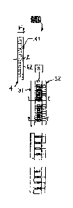
Fig. 1 Is a general sequential representation of an overmoulding cycle of a
main embodiment of the method according to the invention.
Fig. 2 shows step 1 of the method, wherein the mould is closed and the
grab arm is in a standby position.
Fig. 3 is a cross section along the line DID of the device represented in the
previous Fig. 2.
Fig. 4 is an analogous representation to the previous Fig. 3, consisting in a
cross-sectional view through the line A-A, though in this case with regard
to the inner preform as the finished product.
Fig. 5 represents the following phase or step 2, wherein the mould is
opened.
Fig. 6 represents a section along the line E-E in the previous Fig. 5, on
which the topmost 32 products constitute the composite preforms, with
inner preforms.
Fig. 7 is an analogous representation to the previous Fig. 6, though of a
section along the line B-B, with representation of the bottommost 32
products, which only represent the 32 inner preforms.
Fig. 8 is a schematic representation of the thus formed finished product,
consisting of the aforementioned composite preforms, in which the inner
preform is accommodated.
In addition, Fig. 9 shows the third phase of the method according to the
invention, wherein the grab arm with the vacuum plate, which was in the
standby position, now receives all products from the cores.
Fig. 10 is a sectional representation along the line C-C in the previous Fig.
9, showing a cross section, wherein the bottommost 32 products, being the
inner preforms, are transferred into the vacuum plate.
Fig. 11 schematically represents the fourth step of the method according to
the invention, wherein the grab arm moves upwards with the vacuum plate
with the injection moulded products.
In addition, Fig. 12 shows a cross section along the line G-G in the
previous Fig. 11, wherein the injection moulded inner preforms are on the
topmost cores.
CA 02893193 2015-05-29
WO 2014/082140
1 4 PCT/BE2013/000062
Fig, 13 represents a 3D perspective view of a detail of the mould
components.
Fig. 14 represents a front view of a detail of the mould components
according to the previous Fig. 13.
Fig. 16 represents a detail in enlarged view from Figs. 1 & 2 respectively.
Figs. 16-23 each represent a view of the robot components.
Figs. 24 and 26 are a mixed representation of a composite preform
according to the invention as a semi-finished product, especially obtained
by applying the method as represented in Fig. 1,
Figs, 26 and 27 show a combined application of overmoulding and coating
on a preform, resp. the wall section thereof.
Fig. 28 et seq, show a combined application of overmoulding and coating
on a preform, thereby including zebra states.
Description
Fig. 1 shows in partial views a to d a general sequential representation of
overmoulding with, in (1)1, an injection mould 3 which is closed; in 1)2, the
mould which is opened into its 2 mould halves, 31 as the core side and 32 as
the cavity side; in 0)3, a grab arm 4, which arrives therebetween and receives
products 11, 12, and finally, in (1:14, the grab arm 4, which places
bottommost
products 12 onto topmost cores 31'.
Fig. 2 shows said one grab arm 4, which is provided with a vacuum plate 40
for the reception of injection moulded products 11, 12. Opposite thereto, the
relevant mould plate 31, constituting the movable side, is depicted, having
for example 32 cores intended for the composite preforms 10 and 32 cores
for the inner preforms 12, which each occupy virtually half of the plate
surface, in this case on the top half. The mould plate 32, constituting the
fixed side, correspondingly has 32.cavities for the composite preform and a
further set of 32 cavities intended for the inner preform, which occupy the
other half of the plate surface, in this case the bottom half.
Fig. 3 shows the mould 3, closed in step 1 of the method, in the closed state,
.. and the grab arm 4 in a standby position.
CA 02893193 2015-05-29
WO 2014/082140 15 PCT/BE2013/000062
In Fig. 4, the mould plate is represented as the movable side 31 opposite the
mould plate represented as the fixed side 32, in which the cavities for the
composite preform 10 are also depicted, in which the core is incorporated
therefor, with therebetween the finished composite preform 10 with injected
inner preform 12.
Fig. 5 is an analogous representation to the previous Fig. 4, consisting in a
cross-sectional view through the line A-A, though in this case with regard to
the inner preform 12 as the finish ed product.
Fig. 6 represents the following phase 2, wherein the mould 3 is opened, in
particular with a section along the line E-E in the previous Fig. 5, on
which the topmost 32 products constitute the composite preforms 10,
with inner preforms.
Fig. 7 is an analogous representation to the previous Fig. 6, though of
a section along the line B-B, with representation of the bottommost
32 products, which represent only the 32 inner preforms.
.. Fig. 8 is a schematic reproducti on of the so formed finished product
consisting of the aforementioned composite preform, in which the inner
preform is accommodated.
In addition, Fig. 9 shows the third phase of the method, wherein the grab arm
4 with the vacuum plate 40, which was in the standby position, now receives
all products from the cores 33.
Hg. 10 is a sectional representation along the line C-C in the previous Fig.
9 showing a cross section, wherein the bottommost 32 products, being
the inner preforms, have been transferred into the vacuum plate 40.
Fig. 11 schematically represents the fourth step of the method according to
the invention, wherein the grab arm moves upwards with the vacuum plate
with t he injection moulded products. Here, the 32 bottommost products, being
.. the inner preforms, are transferred onto the cores 33 of the 32 topmost
Date Recue/Date Received 2022-03-15
CA 02893193 2015-05-29
WO 2014/082140 16 PCT/BE2013/000062
composite preforms 10. Next, the topmost finished products are deposited
onto a discharge conveyor 100.
In addition, Fig. 12 shows a cross section along the line G-G in the previous
Fig., wherein the injection moulded inner preforms 12 are seated on the
topmost cores 33.
The robot arm then moves further vertically, with the 32 topmost products,
being the composite preforms, therein, wherein these are further expelled
from the vacuum plate 40 and are thus ready for packing.
Once the robot arm 41 has disappeared from between the mould 3, the mould
can reclose, just as in step 1. This is then ready to injection mould the
following products, being 32 integrated preforms 10 at the top and 32 inner
preforms 12 at the bottom.
The overmoulding method can be used to produce bicolour preforms. For
this, the inner and outer preform 11 are sprayed a different colour, or only
the inner or outer preform is coloured. As a result of selective recesses in
the inner preform 12, certain specific designs and variations in colours can
be obtained.
For example, an opaquely coloured inner preform, wherein in the longitudinal
axis of the preform a complete recess is provided, and a transparent outer
preform 11. This gives rise to a transparent window over the full length of
the
preform and bottle, whereby the fill level of the bottle can be observed.
As far as the addition of two different materials is concerned, the described
method for the production of overmoulding preforms likewise allows the inner
and the outer preform 11 to be injection moulded in another material. This
can have special advantages for, for example, gas barrier, moisture barrier
or hot-fill applications. The outer preform 11 can be produced from standard
PET here, and the inner preform 12 can be produced from a high barrier or
hot-fill material. If so desired, this allows the use of a higher share of
secondary material for barrier applications compared with known multilayer
preforms.
CA 02893193 2015-05-29
WO 2014/082140 17 PCT/BE2013/000062
For hot-fill applications, wherein the complete bottle must standardly be
made of expensive hot-fill material, the inner preform alone may consist of
secondary material. For further applications, the inner preform could consist,
for example, of a poiyolefin, and the outer preform of PET. This bottle
combines the mechanical and gas barrier properties of PET with the chemical
barrier, moisture barrier and thermal properties of polyolefins.
Even though this can call for a longer vertical movement between the primary
and secondary injection step, it does however ensure two completely
separate hot runners for the primary and secondary material a, b. In addition
to an extreme simplification of the hot runner systems, this ensures greater
flexibility for the material, since the two hot runners can be set at mutually
independent processing temperatures.
Examples of insert-overmoulding with unitized machine:
Insert-overmoulding preforms were produced on a dual-cavity 2K PET
injection machine. The hot runner was mounted such that the A material can
be injected individually into the topmost cavity and the B material can be
injected individually into the bottommost cavity.
The cavities were mounted such that in the bottommost cavity an inner
preform has been produced without screw thread, and in the topmost cavity
an outer preform has been produced with PCO screw thread. In the topmost
cavity a core having a diameter of 0,6 mm less than the core in the
bottommost cavity has been placed.
The take-off robot was programmed such that, after one cycle, the preform
has been taken off the bottommost core and placed on the topmost core,
whilst the finished preform has been removed from the topmost core and
subsequently cooled.
Materials
Test 1: In a first test, an overmoulding preform was produced, the inner layer
was coloured blue in order to be able to visually evaluate both layers.
Weight of inner preform 6,2 g; total weight 25,8 g
35- A material (outer preform): PET, colourless.
- B material (inner preform): PET, coloured blue.
CA 02893193 2015-05-29
WO 2014/082140 18 PCT/BE2013/000062
From the produced preforms, bottles were blown and evaluated. Both layers
were present in the expected ratio and there was good adhesion between the
layers.
Test 2: In a second test, a milk preform having a highest possible light
barrier was produced with overmoulding.
Weight of inner preform 6,5 g; total weight 26,3 g
- A material (outer preform): coloured with 5% white dye.
B material (inner preform): coloured with 1% black dye.
From the produced preforms, bottles were blown and evaluated for light
barrier with a spectrophotometer. The results indicated a markedly improved
light barrier compared with only white coloured bottles.