Sélection de la langue

Search

Sommaire du brevet 2893195 

Énoncé de désistement de responsabilité concernant l'information provenant de tiers

Une partie des informations de ce site Web a été fournie par des sources externes. Le gouvernement du Canada n'assume aucune responsabilité concernant la précision, l'actualité ou la fiabilité des informations fournies par les sources externes. Les utilisateurs qui désirent employer cette information devraient consulter directement la source des informations. Le contenu fourni par les sources externes n'est pas assujetti aux exigences sur les langues officielles, la protection des renseignements personnels et l'accessibilité.

Disponibilité de l'Abrégé et des Revendications

L'apparition de différences dans le texte et l'image des Revendications et de l'Abrégé dépend du moment auquel le document est publié. Les textes des Revendications et de l'Abrégé sont affichés :

  • lorsque la demande peut être examinée par le public;
  • lorsque le brevet est émis (délivrance).
(12) Brevet: (11) CA 2893195
(54) Titre français: ENSEMBLE D'ELEMENTS POUR UNE EOLIENNE, PROCEDE DE MONTAGE ET DE FONCTIONNEMENT
(54) Titre anglais: COMPONENT ARRANGEMENT, ASSEMBLY METHOD, AND OPERATING METHOD
Statut: Périmé et au-delà du délai pour l’annulation
Données bibliographiques
(51) Classification internationale des brevets (CIB):
  • F16C 19/52 (2006.01)
  • F3D 80/70 (2016.01)
  • F16C 19/54 (2006.01)
(72) Inventeurs :
  • HAMBRECHT, RALF (Allemagne)
(73) Titulaires :
  • SENVION SE
(71) Demandeurs :
  • SENVION SE (Allemagne)
(74) Agent: GOWLING WLG (CANADA) LLP
(74) Co-agent:
(45) Délivré: 2018-07-17
(86) Date de dépôt PCT: 2013-12-11
(87) Mise à la disponibilité du public: 2014-07-03
Requête d'examen: 2015-05-29
Licence disponible: S.O.
Cédé au domaine public: S.O.
(25) Langue des documents déposés: Anglais

Traité de coopération en matière de brevets (PCT): Oui
(86) Numéro de la demande PCT: PCT/EP2013/003742
(87) Numéro de publication internationale PCT: EP2013003742
(85) Entrée nationale: 2015-05-29

(30) Données de priorité de la demande:
Numéro de la demande Pays / territoire Date
10 2012 224 423.9 (Allemagne) 2012-12-27

Abrégés

Abrégé français

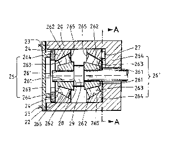
L'invention concerne un ensemble d'éléments pour une éolienne, comprenant un élément externe (20), un élément interne (28) disposé dans l'élément externe (20) et une paire de paliers à roulement (26, 26') qui comprend un premier palier à roulement (26) et un deuxième palier à roulement (26'), en contact l'un avec l'autre, et qui est précontrainte par une force de tension, l'élément interne (28) et l'élément externe (20) étant logés pivotant l'un par rapport à l'autre autour d'un axe de rotation au moyen de la paire de paliers à roulement (26, 26'). L'ensemble d'éléments comporte en outre un capteur de pression (27) disposé dans un flux de la force de tension et destiné à la détermination d'une précontrainte de la paire de paliers à roulement (26, 26'). L'invention concerne en outre un procédé de montage de l'ensemble d'éléments, une éolienne équipée de l'ensemble d'éléments et un procédé de fonctionnement de l'éolienne.


Abrégé anglais


The invention relates to a component arrangement for a
wind turbine comprising an outer component (20, 310,
330, 360), an inner component (28, 320, 338, 350, 368,
380, 390) arranged within the outer component (20, 310,
330, 360), and a rolling bearing pair (26, 26'; 322,
322'; 332, 332'; 352, 352'; 362, 362'; 382, 382'; 392,
392'), which has a first rolling bearing (26, 26'; 322,
322'; 332, 332'; 352, 352'; 362, 362'; 382, 382'; 392,
392') and a second rolling bearing (26, 26'; 322, 322';
332, 332'; 352, 352'; 362, 362'; 382, 382'; 392, 392')
arranged in a manner adjusted relative to one another
and which is preloaded by means of a clamping force,
wherein the inner component (28, 320, 338, 350, 368,
380, 390) and the outer component (20, 310, 330, 360)
are mounted so as to be rotatable relative to one
another about an axis of rotation by means of the
rolling bearing pair (26, 26'; 322, 322'; 332, 332';
352, 352'; 362, 362'; 382, 382'; 392, 392').
The component arrangement according to the invention is
further developed in that the component arrangement
also comprises a pressure sensor (27, 324, 334, 354,
364, 384, 394) for determining a preload of the rolling
bearing pair (26, 26'; 322, 322'; 332, 332'; 352, 352';
362, 362'; 382, 382'; 392, 392'), said pressure sensor
being arranged in a flow of the clamping force.
The invention also provides a method for assembling a
component arrangement according to the invention, a
wind turbine having a component arrangement according
to the invention, and a method for operating a wind
turbine according to the invention.

Revendications

Note : Les revendications sont présentées dans la langue officielle dans laquelle elles ont été soumises.


-32-
Claims
1. A component arrangement for a wind turbine
comprising an outer component (20, 310, 330, 360),
an inner component (28, 320, 338, 350, 368, 380,
390) arranged within the outer component (20, 310,
330, 360), and a rolling bearing pair (26, 26'; 322,
322'; 332, 332'; 352, 352'; 362, 362'; 382, 382';
392, 392'), which has a first rolling bearing (26,
26'; 322, 322'; 332, 332'; 352, 352'; 362, 362';
382, 382'; 392, 392') and a second rolling bearing
(26, 26'; 322, 322'; 332, 332'; 352, 352'; 362,
362'; 382, 382'; 392, 392') arranged in a manner
adjusted relative to one another and which is
preloaded by means of a clamping force, wherein the
inner component (28, 320, 338, 350, 368, 380, 390)
and the outer component (20, 310, 330, 360) are
mounted so as to he rotatable relative to one
another about an axis of rotation by means of the
rolling bearing pair (26, 26'; 322, 322'; 332, 332';
352, 352'; 362, 362'; 382, 382'; 392, 392'),
characterized in that the component arrangement also
comprises a pressure sensor (27, 324, 334, 354, 364,
384, 394) for determining a preload of the rolling
bearing pair (26, 26'; 322, 322'; 332, 332'; 352,
352'; 362, 362'; 382, 382'; 392, 392'), said
pressure sensor is formed as a thin-film sensor and
being arranged in a flow of the clamping force,
wherein the component arrangement has at least a
first pressure sensor (27, 324, 334, 354, 364, 384,
394) arranged at the first rolling bearing (26, 26';
322, 322'; 332, 332'; 352, 352'; 362, 362'; 382,
382'; 392, 392')and a second sensor (27, 324, 334,
354, 364, 384, 394)arranged at the second rolling
bearing (26, 26'; 322, 322'; 332, 332'; 352,
352';362, 362'; 382, 382'; 392, 392').

-33-
2. The component arrangement as claimed in claim 1,
characterized in that the component arrangement
comprises, for preloading the rolling bearing pair
(26, 26'; 322, 322'; 332, 332'; 352, 352'; 362,
362'; 382, 382'; 392, 392') by means of a
predefinable clamping force, a first clamping device
(22, 232, 24; 328; 358; 388; 398) acting on the
first rolling bearing (26, 26'; 322, 322'; 332,
332'; 352, 352'; 362, 362'; 382, 382'; 392, 392')
and/or a second clamping device (22, 232, 24; 328;
358; 388; 398) acting on the second rolling bearing
(26, 26'; 322, 322'; 332, 332'; 352, 352'; 362,
362'; 382, 382'; 392, 392').
3. The component arrangement as claimed in claim 2,
characterized in that the pressure sensor (27, 324,
334, 354, 364, 384, 394) is arranged on a
side of
a rolling bearing (26, 26'; 322, 322'; 332, 332';
352, 352'; 362, 362'; 382, 382'; 392, 392') facing
away from a clamping device (22, 232, 24; 328; 358;
388; 398).
4. The component arrangement as claimed in one of
claims 1 to 3, characterized in that the pressure
sensor (27, 324, 334, 354, 364, 384, 394) formed as
a thin-film sensor (27, 324, 334, 354, 364, 384,
394) has a piezo-electric or piezo-resistive sensor
layer.
5. The component arrangement as claimed in claim 4,
characterized in that the thin-film sensor (27, 324,
334, 354, 364, 384, 394) is formed as an independent
component.
6. The component arrangement as claimed in claim 5,
characterized in that the thin-film sensor is formed
with a layer carrier for the sensor layer

-34-
independent of the other constituent parts of the
component arrangement.
7. The component arrangement as claimed in one of
claims 1 to 6, characterized in that the component
arrangement has an evaluation device for evaluating
measurement signals of the pressure sensor (27, 324,
334, 354, 364, 384, 394).
8. The component arrangement as claimed in one of
claims 1 to 7, characterized in that the component
arrangement comprises at least three pressure
sensors (27, 324, 334, 354, 364, 384, 394).
9. The component arrangement as claimed in claim 8,
wherein the at least three pressure sensors are
arranged in a plane oriented transversely to the
axis of rotation.
10. The component arrangement as claimed in one of
claims 1 to 9, characterized in that the component
arrangement is formed as a constituent part for a
power train (10) of the wind turbine.
11. The component arrangement as claimed in claim 10,
characterized in that the component arrangement is
formed as a rotor bearing, as a transmission (14),
as a generator (16), or as part of a rotor bearing,
part of a transmission (14), or part of a generator
(16).
12. A method for assembling a component arrangement as
claimed in one of claims 1 to 11, said method having
the following method steps:
calibrating at least one pressure sensor (27, 324,
334, 354, 364, 384, 394) of the component
arrangement,

-35-
- preloading the rolling bearing pair (26, 26'; 322,
322'; 332, 332'; 352, 352'; 362, 362'; 382, 382';
392, 392') of the component arrangement with a
predefinable clamping force,
- determining an actual value for a preload of the
rolling bearing pair (26, 26'; 322, 322'; 332, 332';
352, 352'; 362, 362'; 382, 382'; 392, 392') by means
of the at least one pressure sensor (27, 324, 334,
354, 364, 384, 394),
- comparing the actual value with a predefined
tolerance range around a target value for the
preload, and
- where appropriate, adapting the clamping force when
the actual value lies outside the tolerance range.
13. The method as claimed in claim 12, characterized in
that the at least one pressure sensor (27, 324, 334,
354, 364, 384, 394) is calibrated in an assembly
position of the component arrangement with
vertically arranged axis of rotation without
application of a clamping force with utilization of
a known mass of one or more of the inner component
(28, 320, 338, 350, 368, 380, 390), the outer
component (20, 310, 330, 360), one of the two
rolling bearings (26, 26'; 322, 322'; 332, 332';
352, 352'; 362, 362'; 382, 382'; 392, 392'), and
both rolling bearings (26, 26'; 322, 322'; 332,
332'; 352, 352'; 362, 362'; 382, 382'; 392, 392').
14. A wind turbine having a component arrangement,
wherein the component arrangement has an outer
component (20, 310, 330, 360), an inner component
(28, 320, 338, 350, 368, 380, 390) arranged within
the outer component (20, 310, 330, 360), and a

-36-
rolling bearing pair (26, 26'; 322, 322'; 332, 332';
352, 352'; 362, 362'; 382, 382'; 392, 392'), which
has a first rolling bearing (26, 26'; 322, 322';
332, 332'; 352, 352'; 362, 362'; 382, 382'; 392,
392') and a second rolling bearing (26, 26'; 322,
322'; 332, 332'; 352, 352'; 362, 362'; 382, 382';
392, 392') arranged in a manner adjusted relative
to one another and which is preloaded by means of a
clamping force, wherein the inner component (28,
320, 338, 350, 368, 380, 390) and the outer
component (20, 310, 330, 360) are mounted so as to
be rotatable relative to one another about an axis
of rotation by means of the rolling bearing pair
(26, 26'; 322, 322'; 332, 332'; 352, 352'; 362,
362'; 382, 382'; 392, 392'), characterized in that
the component arrangement also comprises a pressure
sensor (27, 324, 334, 354, 364, 384, 394) for
determining a preload of the rolling bearing pair
(26, 26'; 322, 322'; 332, 332'; 352, 352'; 362,
362'; 382, 382'; 392, 392'), said pressure sensor
being arranged in a flow of the clamping force,
wherein the component arrangement has at least a
first pressure sensor (27, 324, 334, 354, 364, 384,
394) arranged at the first rolling bearing (26, 26';
322, 322'; 332, 332'; 352, 352'; 362, 362'; 382,
382'; 392, 392')and a second sensor (27, 324, 334,
354, 364, 384, 394)arranged at the second rolling
bearing (26, 26'; 322, 322'; 332, 332'; 352,
352';362, 362'; 382, 382'; 392, 392').
15. A wind turbine as claimed in claim 14 having a
component arrangement as claimed in one of claims 1
to 11.
16. The wind turbine as claimed in claims 14 or 15,
characterized in that the wind turbine comprises an
operation monitoring system for identifying
operational disruptions.

-37-
17. The wind turbine as claimed in claim 16, wherein the
operating monitoring system comprises an evaluation
device for evaluating measurement signals of at
least one pressure sensor (27, 324, 334, 354, 364,
384, 394) of the component arrangement or is
connected or can be connected to an evaluation
device for evaluating measurement signals of at
least one pressure sensor (27, 324, 334, 354, 364,
384, 394) of the component arrangement.
18. A method for operating a wind turbine, having a
component arrangement comprising an outer component
(20, 310, 330, 360), an inner component (28, 320,
338, 350, 368, 380, 390) arranged within the outer
component (20, 310, 330, 360), and a rolling bearing
pair (26, 26'; 322, 322'; 332, 332'; 352, 352'; 362,
362'; 382, 382'; 392, 392'), which has a first
rolling bearing (26, 26'; 322, 322'; 332, 332'; 352,
352'; 362, 362'; 382, 382'; 392, 392') and a second
rolling bearing (26, 26'; 322, 322'; 332, 332'; 352,
352'; 362, 362'; 382, 382'; 392, 392') arranged in
a manner adjusted relative to one another and which
is preloaded by means of an axially acting clamping
force, wherein the inner component (28, 320, 338,
350, 368, 380, 390) and the outer component (20,
310, 330, 360) are mounted so as to be rotatable
relative to one another about an axis of rotation
by means of the rolling bearing pair (26, 26'; 322,
322'; 332, 332'; 352, 352'; 362, 362'; 382, 382';
392, 392'), wherein the component arrangement has
at least a first pressure sensor (27, 324, 334, 354,
364, 384, 394) arranged at the first rolling bearing
(26, 26'; 322, 322'; 332, 332'; 352, 352'; 362,
362'; 382, 382'; 392, 392')and a second sensor (27,
324, 334, 354, 364, 384, 394)arranged at the second
rolling bearing (26, 26'; 322, 322'; 332, 332'; 352,

-38-
352';362, 362'; 382, 382'; 392, 392'),wherein the
method comprises the following method steps:
- determining an actual value for the preload of the
rolling bearing pair (26, 26'; 322, 322'; 332, 332';
352, 352'; 362, 362'; 382, 382'; 392, 392'), by
means of a pressure sensor (27, 324, 334, 354, 364,
384, 394) arranged in a flow of the clamping force;
- comparing the actual value with a predefined first
reference range around a target value for the
preload; and
- interrupting the operation of the wind turbine when
the actual value lies outside the first reference
range.
19. The method as claimed in claim 18, wherein the wind
turbine is as claimed in anyone of claims 14 to 17.
20. The method as claimed in claims 18 or 19,
characterized in that the determined actual value
for the preload is compared with a predefined second
reference range around the target value for the
preload, wherein the clamping force is adapted
during a subsequent operation interruption of the
wind turbine, when the actual value lies outside the
second reference range.
21. The method as claimed in claim 20, characterized in
that the determined actual value for the preload is
characterized with the predefined second reference
range around the target value for the preload which
is a sub-range of the first reference range.

-39-
22. The method as claimed in claims 20 or 21, wherein
the clamp force is adapted during a subsequent
routinely occurring, operation interruption of the
wind turbine.

Description

Note : Les descriptions sont présentées dans la langue officielle dans laquelle elles ont été soumises.


CA 02893195 2015-05-29
- 1 -
Component arrangement, assembly method, and operating
method
Description
The invention relates to a component arrangement for a
wind turbine comprising an outer component, an inner
component arranged within the outer component, and a
rolling bearing pair, which has a first rolling bearing
and a second rolling bearing arranged in a manner
adjusted relative to one another and which is preloaded
by means of a clamping force, wherein the inner
component and the outer component are mounted so as to
be rotatable relative to one another about an axis of
rotation by means of the rolling bearing pair. The
invention also relates to a method for assembling a
bearing arrangement of this type. The invention
additionally relates to a wind turbine and a method for
operating a wind turbine.
In modern wind turbines adjusted bearings are used at
various locations, for example as rotor bearing, as
shaft bearing or as bearing for movable components
within a transmission or a generator of the wind
turbine.
An adjusted bearing generally comprises two rolling
bearings, which support two components rotatable
relative to one another radially, i.e. transversely to
the axis of rotation, against one another. Axially,
i.e. parallel to the axis of rotation, the two rolling
bearings are preloaded against one another. Adjusted
bearings have the advantage that they can take up
radial forces, axial forces and tilting moments, and in
so doing are free of play axially.
The correct preload of the bearing is of particular
importance for the functional capability and service
life of an adjusted bearing. If the preload is too

CA 02893195 2015-05-29
- 2 -
weak, there is the risk that the rolling bearings or
the rolling bearing set will slip and that slip damage
could be sustained, and that the bearing is no longer
free of play under load and as a result in particular
the rolling bearings will be loaded in a non-uniform
manner, which leads to excessively strong peak loads.
If the preload is too strong, the rolling bearings will
also be excessively loaded. In both cases the
functionality of the bearing will be impaired and the
mechanical efficacy of the wind turbine will be
reduced, for example as a result of increased bearing
friction. At the same time, the service life of the
bearing will be significantly reduced, in particular as
a result of increased wear.
In order to avoid consequential damage caused by
damaged bearings, modern wind turbines often have
monitoring systems that can identify bearing damage,
for example on the basis of increased vibrations.
Abnormal bearings are generally replaced in good time,
however this is regularly associated with considerable
cost and involves downtimes of the wind turbine with
corresponding loss of profit. It has been found in
practice that the calculated service life of a bearing
often is not reached in this case.
Proceeding from this prior art, the object of the
invention is to improve the service life of an adjusted
bearing of a wind turbine and to avoid the losses of
income of the wind turbine on account of limited
functionality of the adjusted bearing.
This object is achieved in accordance with the
invention by a component arrangement for a wind turbine
comprising an outer component, an inner component
arranged within the outer component, and a rolling
bearing pair, which has a first rolling bearing and a
second rolling bearing arranged in a manner adjusted

CA 02893195 2015-05-29
- 3 -
relative to one another and which is preloaded by means
of a clamping force, wherein the inner component and
the outer component are mounted so as to be rotatable
relative to one another about an axis of rotation by
means of the rolling bearing pair, wherein the
component arrangement according to the invention also
comprises a pressure sensor for determining a preload
of the rolling bearing pair, said pressure sensor being
arranged in a flow of the clamping force.
It is in particular an advantage of the invention that
one of the primary causes of bearing damage,
specifically an incorrect preload, in particular an
excessively high or excessively low preload, can be
identified already before the occurrence of bearing
damage with noticeable effects, for example reduced
smoothness, increased vibration and noise emission, or
increased heat development in the bearing. A correction
or adaptation of the preload, in particular by
appropriate modification of the clamping force, is thus
made possible before damage occurs at the bearing, in
particular at the rolling bearings. The optimal
functionality of the bearing formed by means of the
rolling bearings is thus ensured, the service life of
the rolling bearings is improved, and a reduction in
profits of a wind turbine as a result of limited
functionality of the bearing as a whole or of the
rolling bearings individually is thus avoided.
A component in the sense of the invention can be formed
in one piece or can comprise a number of sub-components
connected to one another detachably or non-detachably.
A rolling bearing in the sense of the invention in
particular has two concentric bearing surfaces facing
one another, between which rolling bearings are
arranged. The rolling bearings for example are
spherical, conical, cylindrical, needle-shaped or

CA 02893195 2015-05-29
- 4 -
barrel-shaped and roll over the bearing surfaces as the
bearing surfaces are rotated relative to one another.
The bearing surfaces can be formed in portions in a
manner complementary to the shape of the rolling
bearings in order to achieve a greater contact area
between rolling bearings and bearing surface and
therefore a higher load-bearing capability of the
rolling bearing.
A rolling bearing also comprises, by way of example, an
inner ring, on the outer periphery of which the inner
of the two bearing surfaces is formed and which is
connected or can be connected to the inner component.
Alternatively the inner bearing surface is formed on a
surface of the inner component, in particular facing
radially outwardly.
A rolling bearing additionally comprises, by way of
example, an outer ring, on the inner periphery of which
the outer of the two bearing surfaces is formed and
which is connected or can be connected to the outer
component. Alternatively the outer bearing surface is
formed on a surface of the outer component, in
particular facing radially inwardly.
A rolling bearing of the component arrangement
according to the invention is in particular designed to
take up or to support radial loads and axial loads in
at least one direction. Rolling bearings of this type
are, for example, angular-contact ball bearings,
tapered-roller bearings, 4-point bearings, spherical
roller bearings, barrel roller bearings, ball roller
bearings, angular-contact cylinder roller bearings, or
cylinder roller bearings or deep-groove ball bearings
with primary pressure angle in the radial or also in
the axial direction, known in the prior art.

CA 02893195 2015-05-29
- 5 -
Within the scope of the invention the specifications
axial and radial each relate to the axis of rotation of
the components mounted or to be mounted rotatably
relative to one another, wherein in particular a
direction along the axis of rotation is referred to as
axial and a direction transversely to the axis of
rotation is referred to as radial.
In accordance with the invention the rolling bearings
are arranged in a manner adjusted relative to one
another. This is understood to mean in particular that
the two rolling bearings of the component arrangement
can each take up or support forces or moments in
opposite axial direction, such that the components of
the component arrangement can be mounted or are mounted
free of play axially by the rolling bearing pair.
The rolling bearing pair is preloaded in accordance
with the invention by means of a clamping force,
wherein a clamping force in the sense of the invention
in particular is a compressive force, which can be
applied to or is applied to the rolling bearing pair or
the rolling bearings individually, in particular in the
axial direction.
A flow of the pumping force is understood within the
scope of the invention to mean in particular the
distribution, support or diversion of the clamping
force within the component arrangement. Radial
components of the flow of force here mostly compensate
for one another, for example by axially symmetrical
construction of the rolling bearings. Axial components
of the flow of force are diverted or supported by at
least one tensile loaded component of the component
arrangement, which in particular is the inner component
or the outer component.

CA 02893195 2015-05-29
- 6 -
The clamping force in particular causes a preload of
the rolling bearing pair. This is understood within the
scope of the invention in particular to mean that the
rolling bearings of the rolling bearing pair are
pressed together by means of the clamping force in such
a way that each of the rolling bearings has an
undersize or an overall height reduction or overall
height compression.
A preload of the rolling bearing pair caused by the
clamping force is determined in accordance with the
invention by means of a pressure sensor, which is
arranged within the flow of the clamping force, for
example at the transition between a rolling bearing and
a component or within a rolling bearing.
The clamping force is predefined for example during the
assembly of a component arrangement according to the
invention and is adjusted repeatedly to an optimal
value with determination of the preload by means of the
pressure sensor.
The component arrangement preferably comprises, for
preloading the rolling bearing pair by means of a
predefinable clamping force, a first clamping device
acting on the first rolling bearing and/or a second
clamping device acting on the second rolling bearing.
A clamping device in particular has a stop for a
rolling bearing, which stop is displaceable in the
axial direction and is fastened or can be fastened in
particular detachably to the first component or the
second component.
A stop displaceable axially or in the axial direction
is provided for example with use of suitable screw
connections, inserted gauge plates of adapted
thickness, hydraulically or pneumatically spreadable

CA 02893195 2015-05-29
- 7 -
spacer rings, hydraulically preloadable shaft nuts, or
bolts fixed in predetermined position by transverse
press-fit connection. In particular, a simple
modification or adaptation of the clamping force is
enabled hereby.
If merely one clamping device is provided, the rolling
bearing pair is preloaded from one side. This generally
results, with a modification of the clamping force, in
an axial displacement of the inner component and of the
outer component relative to one another, which may be
undesirable in the individual case.
If, by contrast, two clamping devices are provided, the
rolling bearing pair is preloaded in particular from
both sides. An axial adjustment or orientation of the
inner component and of the outer component relative to
one another with simultaneous adaptation of the
clamping force is thus made possible advantageously.
It is also preferable when the pressure sensor is
arranged on a side of a rolling bearing facing away
from a clamping device. As a result, when establishing
or determining the clamping force, any preload loss
occurring between the clamping device and the pressure
sensor, for example on account of friction or plastic
deformation within the flow of clamping force, is
advantageously taken into consideration. A greater
accuracy when establishing the preload is thus
achieved.
When merely one clamping device is provided on one of
the two rolling bearings, the pressure sensor is
preferably arranged on the other of the two rolling
bearings, in particular on the side facing away from
the rolling bearing having the clamping device. Optimal
accuracy when determining a mean preload of both
rolling bearings is achieved in this way.

,
CA 02893195 2015-05-29
- 8 -
A particularly preferred pressure sensor is formed as a
thin-film sensor, in particular having a piezo-electric
or piezo-resistive sensor layer. Known thin-film
sensors generally have thicknesses of less than one
millimeter up to a few micrometers, wherein the
thickness is independent of a pressure to be determined
by means of the sensor or is only dependent thereon to
a very small extent.
This results in particular in the advantage that the
pressure sensor arranged in the flow of clamping force
does not significantly influence the axial extension of
the bearing arrangement and thus the clamping force. In
addition, the axial orientation of the mounted
components relative to one another is not influenced by
the pressure sensor.
A further advantage of a thin-film sensor lies in the
fact that sensors of this type can be used in a very
versatile manner. By way of example it is possible to
apply the sensor layer directly to a component, for
example to a functional surface, in particular a
bearing surface or contact surface, of a bearing ring
within a rolling bearing. Integrated thin-film sensors
of this type then allow the direct measurement of a
clamping force present within a rolling bearing.
Alternatively, the thin-film sensor is formed as an
independent component, in particular with a layer
carrier for the sensor layer independent of the other
constituent parts of the component arrangement.
Suitable layer carriers are, for example, films or thin
plates made of plastic, metal or ceramic.
Thin-film sensors formed as independent components are
in particular much more economical than integrated

CA 02893195 2015-05-29
- 9 -
thin-film sensors and can be replaced easily and
economically in the case of defects.
In a preferred development of the invention the
component arrangement has an evaluation device for
evaluating measurement signals of the pressure sensor.
In particular, an automatic and/or regular
determination of the clamping force is thus made
possible, in particular also during running operation
of the wind turbine.
Additionally or alternatively the component arrangement
for example has a connector for connection of the
pressure sensor to an external evaluation device for
evaluation of measurement signals of the pressure
sensor. A single evaluation device is thus available
for a number of component arrangements or pressure
sensors thereof.
The accuracy when determining the preload of the two
rolling bearings is further increased in that the
component arrangement according to the invention has at
least a first pressure sensor arranged at the first
rolling bearing and a second pressure sensor arranged
at the second rolling bearing. A separate determination
of the preload of the first rolling bearing and the
preload of the second rolling bearing is thus made
possible.
In addition, a two-way function check is ensured with a
first pressure sensor and a second pressure sensor, and
an increased safeguarding against failure is provided
because, even in the event of a defect of one of the
two pressure sensors, a preload can still be
established or determined for both rolling bearings by
means of the other pressure sensor.

CA 02893195 2015-05-29
- 10 -
The invention also includes embodiments with further
pressure sensors, wherein for example a pressure sensor
is arranged on both sides of each of the two rolling
bearings.
The component arrangement preferably comprises at least
three pressure sensors, which in particular are
arranged in a plane oriented transversely to the axis
of rotation. By way of example, the at least three
pressure sensors are arranged along a circle about the
axis of rotation at equal distance from one another.
Besides the preload, a radial asymmetry of the preload
can thus also be determined and therefore compensated
for suitably.
An asymmetry of the preload, which for example can be
caused by non-uniform tightening of the fastening
screws of a bearing cover, leads to a non-uniform
loading of the rolling bearings, whereby the rolling
bearings may each have areas along their periphery with
excessively high preload and/or areas with excessively
low preload, even when the preload averaged over the
periphery corresponds to the corresponding setting. As
with a preload that as a whole is incorrect, the
likelihood of damage at the rolling bearings
potentially leading to premature failure rises also
with an asymmetry of the preload.
An asymmetrical preload is produced for example on
account of a radial loading of the component
arrangement when the rolling bearings are not oriented
exactly parallel to one another and/or are not oriented
exactly concentrically about the axis of rotation, or
when the clamping force has a radial asymmetry.
Conversely, it is possible to compensate for a radial
asymmetry of the preload by means of a suitably
selected asymmetry of the clamping force.

,
CA 02893195 2015-05-29
- 11 -
The component arrangement is preferably formed as a
constituent part for a power train of the wind turbine,
in particular as a rotor bearing, as a transmission, as
a generator, or as part of a rotor bearing, part of a
transmission, or part of a generator.
By way of example, the inner component is a rotor shaft
and the outer component is a mount for a rotor of the
wind turbine driving the rotor shaft.
The inner component and/or the outer component of the
component arrangement may also each be a constituent
part of a transmission or of a generator of the wind
turbine.
The object forming the basis of the invention is also
achieved by a method for assembling a component
arrangement according to the invention, said method
having the following method steps:
- calibrating at least one pressure sensor of the
component arrangement,
- preloading the rolling bearing pair of the
component arrangement with a predefinable clamping
force,
- determining an actual value for a preload of the
rolling bearing pair by means of the at least one
pressure sensor,
- comparing the actual value with a predefined
tolerance range around a predefined target value
for the preload, and

CA 02893195 2015-05-29
- 12 -
- where
appropriate, adapting the clamping force
when the actual value lies outside the tolerance
range.
The target value for the preload is in particular
predefined on the basis of an optimal preload under
consideration of an anticipated loading of the rolling
bearing pair during operation.
The tolerance range is predefined in particular on the
basis of the acceptable assembly tolerances and
specifies the admissible symmetric or asymmetric
deviation of the actual value from the target value in
the peripheral direction.
If the established actual value for the preload lies
outside the tolerance range, the clamping force is
adapted in accordance with the invention. This means in
particular that the clamping force with which the
rolling bearing pair is preloaded is increased if the
actual value is below the target value, in particular
below a lower limit of the tolerance range, and that
the clamping force is reduced if the actual value is
greater than the target value, in particular greater
than an upper limit of the tolerance range.
The at least one pressure sensor is calibrated in
accordance with the invention in order to determine the
actual value in a sufficiently accurate manner.
The pressure sensor is preferably calibrated in an
assembly position of the component arrangement with
vertically arranged axis of rotation without
application of a clamping force with utilization of a
known mass of the inner component and/or the outer
component and/or of one of the two rolling bearings
and/or both rolling bearings.

CA 02893195 2015-05-29
- 13 -
In the assembly position with vertically arranged or
oriented axis of rotation, the pressure sensor is
loaded in particular by the weight force of the inner
component and/or the outer component and/or of the
rolling bearings, provided these are arranged in the
assembly position above the pressure sensor and rest
directly or indirectly on the pressure sensor. The
force acting on the pressure sensor is given here
directly from the known masses of the components
resting on the pressure sensor, such that a very
accurately known a calibration point is provided.
If a number of components rest above one another on the
pressure sensor, a number of calibration points are
given accordingly by adding the individual components
incrementally, such that even non-linear pressure
sensors can be calibrated accordingly. In addition, a
zero-point calibration of the pressure sensor is
provided before adding the first or, based on the
assembly position, lowermost component, i.e. provided
the pressure sensor is still unloaded.
The object forming the basis of the invention is also
achieved by a wind turbine having a component
arrangement, wherein the component arrangement has an
outer component, an inner component arranged within the
outer component, and a rolling bearing pair, which has
a first rolling bearing and a second rolling bearing
arranged in a manner adjusted relative to one another
and which is preloaded by means of a clamping force,
wherein the inner component and the outer component are
mounted so as to be rotatable relative to one another
about an axis of rotation by means of the rolling
bearing pair, wherein the component arrangement
according to the invention is further developed in that
the component arrangement also comprises a pressure
sensor for determining a preload of the rolling bearing
pair, said pressure sensor being arranged in a flow of

CA 02893195 2015-05-29
- 14 -
the clamping force. The component arrangement is in
particular a previously described component arrangement
according to the invention.
A particularly preferred wind turbine comprises a
plurality of component arrangements according to the
invention. In particular, each adjusted bearing of the
wind turbine can be formed as a constituent part of a
component arrangement according to the invention having
a pressure sensor for determining a preload of the
bearing.
The wind turbine preferably comprises an operation
monitoring system for identifying operational
disruptions, wherein in particular the operating
monitoring system comprises an evaluation device for
evaluating measurement signals of at least one pressure
sensor of the component arrangement or is connected or
can be connected to an evaluation device for evaluating
measurement signals of the at least one pressure sensor
of the component arrangement.
The object forming the basis of the invention is
additionally achieved by a method for operating a wind
turbine, in particular a previously described wind
turbine according to the invention, having a component
arrangement comprising an outer component, an inner
component arranged within the outer component, and a
rolling bearing pair, which has a first rolling bearing
and a second rolling bearing arranged in a manner
adjusted relative to one another and is preloaded by
means of a clamping force, wherein the inner component
and the outer component are mounted so as to be
rotatable relative to one another by means of the
rolling bearing pair, wherein the method comprises the
following method steps:

CA 02893195 2015-05-29
- 15 -
- determining an actual value for the preload of the
rolling bearing pair, in particular by means of a
pressure sensor arranged in a flow of the clamping
force;
- comparing the actual value with a predefined first
reference range around a target value for the
preload; and
- interrupting the
operation of the wind turbine
when the actual value lies outside the reference
range.
The method can be carried out in any operating modes of
the wind turbine, in particular in full-load operation,
in partial-load operation and in load-free operation
and during downtime of the wind turbine. When it is
determined here are that the preload of the rolling
bearing pair lies outside the reference range, the
operation of the wind turbine is interrupted in
accordance with the invention and/or an alarm signal is
sent to a remote monitoring center. This is understood
to mean in particular that the wind turbine is
transferred automatically or manually into a secured
downtime mode. This can be caused for example by
extremely low or extremely high external temperatures.
The wind turbine is then released again for normal
operation, in particular when a newly determined actual
value for the preload of the rolling bearing pair, for
example following adaptation of the clamping force,
lies within the reference range.
A particularly preferred method according to the
invention is characterized in that the actual value for
the preload is compared with a second reference range
around the target value for the preload, which in
particular is a sub-range of the first reference range,
wherein the clamping force is adapted during a

CA 02893195 2015-05-29
- 16 -
subsequent, in particular routinely occurring,
operation interruption of the wind turbine, when the
actual value lies outside the second reference range.
It is thus made possible, even with small deviations of
the actual value for the preload from the target value,
to schedule in the adaptation of the clamping force,
which can then be performed during routine maintenance
of the wind turbine. An operation interruption
specifically for the adaptation of the clamping force
is thus avoided. The second reference range is
therefore in particular to be measured so narrowly
around the target value that the rolling bearing pair
can continue to be operated without damage.
In accordance with an advantageous development of the
invention the reference range is determined in
accordance with a temperature. It is thus made possible
advantageously to compensate for the considerable
temperature-induced longitudinal extension in the case
of large components and therefore to observe narrower
tolerances of the reference range. The temperature here
is preferably the temperature measured in the machine
nacelle or in the transmission.
The method according to the invention for operating a
wind turbine is preferably further developed such that
the operating loads of the bearing are recorded. By
means of an evaluation, known in the prior art, of the
recorded operating loads, in particular in the form of
load collectives, a prognosis of the anticipated
remaining service life of the bearings is thus
possible.
Further features of the invention will become clear
from the description of embodiments according to the
invention together with the claims and the accompanying
drawings. Embodiments according to the invention may

CA 02893195 2015-05-29
- 17 -
satisfy individual features or a combination of a
number of features.
The invention will be described hereinafter without
limitation of the general inventive concept on the
basis of exemplary embodiments with reference to the
drawings, wherein reference is made expressly to the
drawings with regard to all details according to the
invention not explained in greater detail in the text.
In the drawings:
figure 1 schematically shows a typical power train of
a wind turbine,
figure 2 schematically shows a bearing arrangement
according to the invention in longitudinal
axial sectional illustration,
figure 3 schematically shows the bearing arrangement
according to the invention from figure 2 in a
transverse axial sectional illustration, and
figure 4 schematically shows a sectional illustration
of a transmission according to the invention
of a wind turbine according to the invention.
In the drawings, like or equivalent elements and/or
parts are provided in each case with the same reference
numerals, such that there is no need for a renewed
presentation in each case.
Figure 1 schematically shows a typical power train 10
of a wind turbine. The power train 10 comprises a rotor
12 having a rotor hub and at least one rotor blade,
which is rotated by wind power. The rotation of the
rotor 12 is transmitted via a rotor shaft 13 to a
transmission 14. The transmission 14 is connected on
the output side via a transmission shaft 15 to a

CA 02893195 2015-05-29
- 18 -
generator 16, which converts the mechanical energy
removed from the wind by means of the rotor 12 into
electrical energy. In contrast from the embodiment
illustrated in figure 1, the invention can also be used
in rolling bearings of wind turbines without
transmission.
The transmission 14 is usually formed in such a way
that the speed of rotation of the transmission shaft 15
is greater than the speed of rotation of the rotor
shaft 13. Accordingly, the rotor shaft 13 is often also
referred to as the slow shaft, and the generator shaft
is often also referred to as the quick shaft.
15 Further constituent parts of a typical power train 10,
in particular clutches and brakes, are not illustrated
in figure 1.
The rotating or rotatable elements of the power train,
in particular the rotor shaft 13, the generator shaft
15 and also rotating or rotatable components within the
transmission 14 and within the generator 16, are
suitably mounted. Adjusted bearings having two rolling
bearings preloaded against one another are generally
used for this purpose, wherein at least one of these
bearings in a wind turbine according to the invention
is provided as a constituent part of a component
arrangement according to the invention.
An example of a component arrangement according to the
invention is shown schematically in figure 2 and figure
3. Here, figure 2 shows a longitudinal axial sectional
illustration and figure 3 shows a transverse axial
sectional illustration in the plane of section A-A
indicated in figure 2.
The component arrangement comprises a shaft 28, which
is mounted concentrically and rotatably within a

CA 02893195 2015-05-29
- 19 -
housing 20. The corresponding axis of rotation is
illustrated in figure 2 as a dashed line. The component
arrangement also comprises a rolling bearing pair
formed of two rolling bearings 26, 26' formed as
tapered-roller bearings, which each have an inner ring
261 resting against the shaft 28 and an outer ring 264
resting against the housing 20. The rolling bearings
26, 26' each comprise conical rolling elements 263,
which each roll over an outer bearing surface 265 of an
outer ring 264 and over an inner bearing surface 262 of
an inner ring 261.
In the axial direction the outer ring 264 of one
rolling bearing 26' rests on a total of three pressure
sensors 27, which in this example are arranged in
recesses 21 on a transverse axial rear wall of the
housing 20. In the case of thin sensors, these are
arranged directly on the housing rear wall. The inner
ring 261 of the same rolling bearing 26' rests against
a stop 29 on the shaft 28 in the opposite direction.
The inner ring 261 of the other rolling bearing 26,
which is arranged mirror-symmetrically with respect to
the rolling bearing 26', likewise rests against the
stop 29 in the axial direction.
On the side opposite the housing rear wall, the housing
20 is closed by means of a housing cover 22 fastened
via screw connections 23 to the housing 20. A spacer
ring 24, which is adapted in terms of the thickness
thereof, i.e. in the longitudinal axial extension
thereof, in such a way that the two rolling bearings
26, 26' and the shaft 28 are preloaded or clamped in
the axial direction by means of a predefined clamping
force between the rear wall of the housing 20 and the
housing cover 22, is located between the housing cover
22 and the outer ring 264 of the rolling bearing 26.

CA 02893195 2015-05-29
- 20 -
A flow of clamping force is thus created running from
the housing cover 22 via the spacer ring 24, the outer
ring 264, the rolling elements 263 and also the inner
ring 261 of the rolling bearing 26, the stop 29 of the
shaft 28, the inner ring 261, the rolling elements 263
and also the outer ring 264 of the left rolling
bearing, and the pressure sensors 27 as far as the rear
wall of the housing 20 and is supported there, whereby
in particular the housing 20 and the screw connections
23 of the housing cover 22 are tensile loaded in the
axial direction.
The inner rings 261, rolling elements 263 and outer
rings 264 of the rolling bearings 26, 26' are pressed
against one another by means of the clamping force to
give an overall height reduction, whereby the rolling
bearings 26, 26' are preloaded. This preload can be
measured or can be determined here by means of the
pressure sensors 27, which are arranged in accordance
with the invention likewise in the flow of the clamping
force.
Ideally, radial components of the preload occurring by
deflection of the clamping force within the rolling
bearings 26, 26' are symmetrical and cancel one another
out accordingly. The rolling bearings 26, 26' under
preload, in particular with application of the clamping
force, are thus oriented parallel to one another and
concentrically with the axis of rotation.
However, in reality, asymmetric radial components of
the preload also occur, in particular on account of
gravitational or weight forces. This is regularly the
case for example with a rotor shaft 13 on account of
the high weight of the rotor 12.
So as to be able to identify or determine an asymmetric
radial component of the preload, three pressure sensors

CA 02893195 2015-05-29
- 21 -
27 are provided, which are arranged along a circle
about the axis of rotation at equal distance from one
another, as illustrated in figure 3.
Figure 4 shows a transmission 14 designed in accordance
with the invention for a power train 10 of a wind
turbine. The figure shows a sectional illustration,
wherein components that visibly cut the plane of
section of the illustration a number of times are
provided in part with just one reference sign for
reasons of clarity.
The transmission 14 shown by way of example has, on the
input side, a shaft mount 312 for a rotor shaft 13 and
has, on the output side, an output shaft 390, which is
connected or can be connected to a generator 16.
The transmission 14 is formed in three stages with a
first planetary gear stage, a second planetary gear
stage and a spur gear stage. The three stages of the
transmission 14 are formed in such a way that the speed
of rotation is increased incrementally, such that the
speed of rotation of the output shaft 390, which is
also referred to as the quick shaft, is much higher
than the speed of rotation of the rotor shaft 13, which
is also referred to as the slow shaft.
The first planetary gear stage comprises a planet
carrier 320 with the shaft mount 312 and at least one
planet gear 330 arranged rotatably on the planet
carrier 320, a stationary ring gear 340 integrated in a
housing 310 of the transmission 14, and also a sun gear
342. The planet gear 330 runs around between the ring
gear 340 and the sun gear 342, wherein the planet gear
330, the ring gear 340, and the sun gear 342 each have
toothings meshing with one another.

CA 02893195 2015-05-29
- 22 -
The planet gear 330 is fastened by means of an axle pin
338 in a corresponding mount of the planet carrier 320
and is mounted rotatably about the axle pin 338 by
means of two rolling bearings 332, 332' formed as
angular-contact ball bearings. The rolling bearings
332, 332' form an adjusted bearing in what is known as
an 0-arrangement.
The planet gear 330 is formed as an internally mounted
gearwheel, against which the outer rings of the rolling
bearings 332, 332' rest, wherein a spacer ring 337 is
arranged between the outer rings. Alternatively, the
outer rings of the rolling bearings 332, 332' can be
radially pressed into the planet gear 330 and thus
connected to the planet gear 330 for conjoint rotation
therewith and in a manner secured against slip. The
inner rings of the rolling bearings 332, 332' are
arranged on the axle pin 338. Alternatively, the inner
or outer ring can be omitted in the case of integrated
bearing races.
The axle pin 338 has a pin head, on which the inner
ring of the rolling bearing 332' is supported axially.
On the opposite side, the axle pin 338 is pressed into
an opening in the planet carrier 320 in such a way that
the rolling bearings 332, 332' are preloaded between
the pin head of the axle pin 338 and the planet carrier
320. The pin head is arranged in a bore of the planet
carrier 320 and is accordingly supported radially. A
tilting of the planet gear 330 relative to the planet
carrier 320 is thus prevented.
Pressure sensors 334 formed as thin-film sensors for
determining the preload of the rolling bearings 332,
332' are arranged between the planet carrier 320 and
the inner ring of the rolling bearing 332. For
operation and readout of the pressure sensors 334, a

CA 02893195 2015-05-29
- 23 -
sensor cabling 336 is provided. This is guided through
the planet carrier 320 to the shaft mount 312.
By way of example, for assembly of the planet gear 330,
the pressure sensors 334 are first arranged on the
planet carrier, the sensor cabling 336 is installed as
far as the shaft mount 312, and an evaluation device
for the pressure sensors 334 is temporarily connected
to the sensor cabling 336. The pressure sensors 334 are
preferably already calibrated and are therefore ready
for use during the ongoing assembly.
The planet gear 330 is then arranged with the two
rolling bearings 332, 332' on the planet carrier 320,
and the axle pin 338 is pressed into the corresponding
mount. The preload of the rolling bearings 332, 332' is
determined or established by means of the pressure
sensors 334 and the evaluation device, and the axle pin
338 is pressed into the mount on the planet carrier 320
until the desired preload is reached. The determination
of the preload and the pressing in of the axle pin 338
can be performed here simultaneously or in turn.
By way of example the evaluation device is then
separated from the sensor cabling 336, and suitable
means are installed in order to ensure, via the sensor
cabling 336 at the shaft mount 312, which rotates in
the transmission used as intended, the operation and
the readout of the pressure sensors 334, also during
operation of the transmission 14. Means suitable for
this purpose are, for example, slip rings or induction
loops.
The planet carrier 320 with the planet gear 330 mounted
thereon is mounted rotatably within the housing 310 by
means of two rolling bearings 322, 322' formed as
angular-contact ball bearings. The rolling bearings
322, 322' each have an inner ring arranged on the

CA 02893195 2015-05-29
- 24 -
planet carrier 320 and an outer ring arranged on the
housing 310, wherein the rolling bearings form an
adjusted bearing in what is known as an X-arrangement.
The bearing of the planet carrier 320 or the two
rolling bearings 322, 322' is also preloaded. For this
purpose, the outer ring of the rolling bearing 322 is
acted on by a clamping force by means of a housing
covered 328 screwed to the housing 310. In order to
adapt the clamping force, gauge plates of suitable
thickness for example can be provided between the
housing cover 328 and the outer ring of one rolling
bearing 322.
Pressure sensors 324 formed as thin-film sensors are
provided between the other rolling bearing 322' and the
housing 310, by means of which pressure sensors the
preload of the rolling bearings 322, 322' can be
determined. The pressure sensors 324 are arranged
uniformly along the periphery of the outer ring of the
rolling bearing 322'. In order to operate and read out
the pressure sensors 324, a sensor cabling 326 is
provided, which is guided through the housing 310. The
sensor cabling 326 is freely accessible on the housing
outer side and for example can be connected to an
evaluation device (not illustrated).
The second planetary gear stage also has a planet
carrier 350 with at least one planet gear 360, a
stationary ring gear 370 and also a sun gear 372. The
planet carrier 350 of the second planetary gear stage
is connected here to the sun gear 342 of the first
planetary gear stage for conjoint rotation therewith.
The second planetary gear stage is dimensioned slightly
smaller than the first planetary gear stage on account
of the higher speed of rotation and accordingly lower
torques occurring, but otherwise is constructed

CA 02893195 2015-05-29
- 25 -
similarly to the first planetary gear stage. With
regard to the bearing of the individual components,
reference is made expediently to the description in
relation to the first planetary gear stage. The planet
gear 360 is also assembled on the planet carrier 350 in
a manner corresponding to the assembly of the planet
gear 330 on the planet carrier 320.
The planetary gear stages are assembled in a preferred
embodiment in particular in succession, starting with
the second planetary gear stage. For this purpose, the
housing 310 of the transmission 14 is first brought
into a first assembly position, in which the axis of
rotation of the planet carrier 350 of the second stage,
illustrated in figure 4 as a dot-and-dash line, is
oriented vertically, wherein the housing part for the
planetary gear stage is arranged above, and the housing
part for the spur gear stage is arranged below.
The pressure sensors 354 and the corresponding sensor
cabling 356 are first installed, and an evaluation
device is connected to the sensor cabling, such that
the pressure sensors 354 are ready for operation during
the running assembly.
The rolling bearing 352, the pre-assembled planet
carrier 350 with at least one planet gear 360, and also
the rolling bearing 352 are now placed in the housing
310 one after the other.
Here, for example, the pressure sensors 354 are read
out with each step, such that a calibration table for
the pressure sensors 354 is created on the basis of the
known masses of the respective components and of the
accordingly known pressure exerted onto the pressure
sensors 354 by the components resting on the pressure
sensors 354.

CA 02893195 2015-05-29
- 26 -
With good linearity, i.e. with linear response
behavior, and good homogeneity, i.e. high similarity in
the response behavior compared with identical thin-film
sensors, of the pressure sensors 354, an offset
calibration may be sufficient, for example by means of
a readout and evaluation of the installed, unloaded
pressure sensors 354. With good linearity, but poor
homogeneity, a two-point calibration is generally
sufficient, for example by means of a readout of the
unloaded pressure sensors 354 and a readout following
placement of all previously described components.
Alternatively or additionally hereto, the pressure
sensors 354 may also have been suitably calibrated
beforehand, for example in a suitable test machine.
The bearing cover 358 is then screwed to the housing
310, and a clamping force is thus applied to the
rolling bearings 352, 352'. The resulting preload of
the rolling bearings is determined on the basis of the
pressure sensors 354. Where appropriate, the clamping
force is adapted, for example by means of gauge sheets
or spacer rings between the bearing cover 358 and the
outer ring of the rolling bearing 352, until the
desired preload of the rolling bearings 352, 352' is
reached. Here, dynamic clamping means, for example
hydraulically spreadable spacer rings, can also be
used, such that the screw connection of the housing
cover does not have to be opened and closed a number of
times.
A further check for correct preload of the rolling
bearings can be implemented for example by rotating the
transmission 14 into the operating position, in which
in particular the axis of rotation of the planet
carrier 350 is oriented horizontally or substantially
horizontally, and by determining the preload of the
rolling bearings 352, 352' with stationary and/or

CA 02893195 2015-05-29
- 27 -
rotating planet carrier 350, again by means of the
pressure sensors 354.
The first planetary gear stage is then assembled in the
same way.
The spur gear stage comprises a spur gear 381 and a
gearwheel 391, which each have a toothing meshing with
one another. The spur gear 381 is connected via an
intermediate shaft 380 to the sun gear 372 of the
second planetary gear stage, whereas the gearwheel 391
is connected to the output shaft 390 of the
transmission 14 for conjoint rotation therewith.
The intermediate shaft 380 is mounted rotatably within
the housing 310 by means of an adjusted bearing having
two rolling bearings 382, 382' formed as angular-
contact ball bearings. The rolling bearings 382, 382'
each have an inner ring arranged on the intermediate
shaft 380 and an outer ring arranged on the housing 310
and form an adjusted bearing in what is known as an X-
arrangement.
The rolling bearings 382, 382' are preloaded by means
of a housing cover 388 screwed to the housing 310,
wherein the housing cover 388 acts on the outer ring of
the rolling bearing 382 with a clamping force. Where
appropriate, an insert plate of suitable thickness is
provided between the housing cover 388 and the outer
ring of the rolling bearing 382 in order to selectively
predefine the clamping force.
One or more pressure sensors 384 formed as thin-film
sensors for determining the preload of the rolling
bearing pair 382, 382' is/are located between the outer
ring of the other rolling bearing 382' and the housing
310. The pressure sensor or the pressure sensors 384
is/are operated and read out via a sensor cabling 386.

CA 02893195 2015-05-29
- 28 -
The sensor cabling 386 is guided here through the
housing 310 to the housing outer side. The sensor
cabling 386 is freely accessible on the housing outer
side and by way of example can be connected to an
evaluation device (not illustrated).
The output shaft 390 is mounted rotatably within the
housing 310, likewise by means of an adjusted bearing
having two rolling bearings 392, 392' formed as
angular-contact ball bearings. The rolling bearings
392, 392' each have an inner ring arranged on the
output shaft 390 and an outer ring arranged on the
housing 310.
A preload of the rolling bearings 392, 392' is achieved
by a housing cover 398 screwed to the housing 310,
which housing cover acts on the outer ring of the
rolling bearing 392 with a clamping force. One or more
pressure sensors 394 formed as thin-film sensors for
determining the preload of the rolling bearing pair
392, 392' and/or the bearing of the output shaft 390
is/are located between the outer ring of the other
rolling bearing 392' and the housing 310.
The pressure sensor or the pressure sensors 394 is/are
operated and read out via a sensor cabling 396. The
sensor cabling 396 for the pressure sensor or the
pressure sensors 398 is guided here through the housing
310. The sensor cabling 396 is freely accessible on the
housing outer side and by way of example can be
connected to an evaluation device (not illustrated).
The spur gear stage is preferably assembled in a second
assembly position of the housing, in which the axes of
rotation of the intermediate shaft 380 and the output
shaft 390 are arranged vertically, wherein the housing
part for the spur gear stage is arranged above, and the
housing part for the planetary gear stage is arranged

CA 02893195 2015-05-29
- 29 -
below. Here, the spur gear stage can be assembled both
before and after the assembly of the planetary gear
stages.
The assembly of the intermediate shaft 380, the rolling
bearings 382, 382', the pressure sensors 384, the
sensor cabling 386 and the housing cover 388 and also
the assembly of the output shaft 390, the rolling
bearings 392, 392', the pressure sensors 394, the
sensor cabling 396 and the housing cover 398 is
performed in each case in accordance with the described
assembly of the planet carrier 350, the rolling
bearings 352, 352', the pressure sensors 354, the
sensor cabling 356 and the housing cover 358.
All specified features, including those to be inferred
from the drawings alone and also individual features
that are disclosed in combination with other features,
are considered to be essential to the invention alone
and in combination. Embodiments according to the
invention can be satisfied by individual features or a
combination of a number of features.

CA 02893195 2015-05-29
- 30 -
List of reference signs
power train
12 rotor
5 13 rotor shaft
14 transmission
quick shaft
16 generator
housing
10 21 recess
22 housing cover
23 screw connection
24 spacer ring
26, 26' tapered roller bearing
15 261 inner ring
262 inner bearing surface
263 conical rolling element
264 outer ring
265 outer bearing surface
20 27 pressure sensor
28 shaft
29 stop
310 housing
312 shaft mount
320 planet carrier
322, 322' rolling bearing
324 thin-film sensor
326 sensor cabling
328 housing cover
330 planet gear
332, 332' rolling bearing
334 thin-film sensor
336 sensor cabling
337 spacer ring
338 axle pin
340 ring gear
342 sun gear
350 planet carrier

CA 02893195 2015-05-29
- 31 -
352, 352' rolling bearing
354 thin-film sensor
356 sensor cabling
358 housing cover
360 planet gear
362, 362' rolling bearing
364 thin-film sensor
366 sensor cabling
367 spacer ring
368 axle pin
370 ring gear
372 sun gear
380 intermediate shaft
381 spur gear
382, 382' rolling bearing
384 thin-film sensor
386 sensor cabling
388 housing cover
390 output shaft
391 gearwheel
392, 392' rolling bearing
394 thin-film sensor
396 sensor cabling
398 housing cover

Dessin représentatif
Une figure unique qui représente un dessin illustrant l'invention.
États administratifs

2024-08-01 : Dans le cadre de la transition vers les Brevets de nouvelle génération (BNG), la base de données sur les brevets canadiens (BDBC) contient désormais un Historique d'événement plus détaillé, qui reproduit le Journal des événements de notre nouvelle solution interne.

Veuillez noter que les événements débutant par « Inactive : » se réfèrent à des événements qui ne sont plus utilisés dans notre nouvelle solution interne.

Pour une meilleure compréhension de l'état de la demande ou brevet qui figure sur cette page, la rubrique Mise en garde , et les descriptions de Brevet , Historique d'événement , Taxes périodiques et Historique des paiements devraient être consultées.

Historique d'événement

Description Date
Le délai pour l'annulation est expiré 2023-06-13
Lettre envoyée 2022-12-12
Lettre envoyée 2022-06-13
Lettre envoyée 2021-12-13
Représentant commun nommé 2019-10-30
Accordé par délivrance 2018-07-17
Inactive : Page couverture publiée 2018-07-16
Préoctroi 2018-06-07
Inactive : Taxe finale reçue 2018-06-07
Un avis d'acceptation est envoyé 2018-04-30
Lettre envoyée 2018-04-30
month 2018-04-30
Un avis d'acceptation est envoyé 2018-04-30
Inactive : Approuvée aux fins d'acceptation (AFA) 2018-04-24
Inactive : Q2 réussi 2018-04-24
Requête pour le changement d'adresse ou de mode de correspondance reçue 2018-01-10
Modification reçue - modification volontaire 2018-01-03
Inactive : CIB désactivée 2017-09-16
Inactive : Dem. de l'examinateur par.30(2) Règles 2017-07-11
Inactive : Rapport - Aucun CQ 2017-07-10
Modification reçue - modification volontaire 2017-04-21
Modification reçue - modification volontaire 2017-02-08
Inactive : Dem. de l'examinateur par.30(2) Règles 2017-01-12
Inactive : Rapport - CQ réussi 2017-01-11
Modification reçue - modification volontaire 2016-09-12
Inactive : CIB attribuée 2016-06-16
Inactive : Dem. de l'examinateur par.30(2) Règles 2016-03-10
Inactive : Rapport - Aucun CQ 2016-03-09
Inactive : CIB expirée 2016-01-01
Inactive : Page couverture publiée 2015-07-02
Inactive : CIB en 1re position 2015-06-09
Lettre envoyée 2015-06-09
Inactive : Acc. récept. de l'entrée phase nat. - RE 2015-06-09
Inactive : CIB attribuée 2015-06-09
Demande reçue - PCT 2015-06-09
Exigences pour l'entrée dans la phase nationale - jugée conforme 2015-05-29
Exigences pour une requête d'examen - jugée conforme 2015-05-29
Toutes les exigences pour l'examen - jugée conforme 2015-05-29
Demande publiée (accessible au public) 2014-07-03

Historique d'abandonnement

Il n'y a pas d'historique d'abandonnement

Taxes périodiques

Le dernier paiement a été reçu le 2017-11-30

Avis : Si le paiement en totalité n'a pas été reçu au plus tard à la date indiquée, une taxe supplémentaire peut être imposée, soit une des taxes suivantes :

  • taxe de rétablissement ;
  • taxe pour paiement en souffrance ; ou
  • taxe additionnelle pour le renversement d'une péremption réputée.

Les taxes sur les brevets sont ajustées au 1er janvier de chaque année. Les montants ci-dessus sont les montants actuels s'ils sont reçus au plus tard le 31 décembre de l'année en cours.
Veuillez vous référer à la page web des taxes sur les brevets de l'OPIC pour voir tous les montants actuels des taxes.

Historique des taxes

Type de taxes Anniversaire Échéance Date payée
Taxe nationale de base - générale 2015-05-29
Requête d'examen - générale 2015-05-29
TM (demande, 2e anniv.) - générale 02 2015-12-11 2015-12-04
TM (demande, 3e anniv.) - générale 03 2016-12-12 2016-11-25
TM (demande, 4e anniv.) - générale 04 2017-12-11 2017-11-30
Taxe finale - générale 2018-06-07
TM (brevet, 5e anniv.) - générale 2018-12-11 2018-11-29
TM (brevet, 6e anniv.) - générale 2019-12-11 2019-11-29
TM (brevet, 7e anniv.) - générale 2020-12-11 2020-12-07
Titulaires au dossier

Les titulaires actuels et antérieures au dossier sont affichés en ordre alphabétique.

Titulaires actuels au dossier
SENVION SE
Titulaires antérieures au dossier
RALF HAMBRECHT
Les propriétaires antérieurs qui ne figurent pas dans la liste des « Propriétaires au dossier » apparaîtront dans d'autres documents au dossier.
Documents

Pour visionner les fichiers sélectionnés, entrer le code reCAPTCHA :


Pour visualiser une image, cliquer sur un lien dans la colonne description du document (Temporairement non-disponible). Pour télécharger l'image (les images), cliquer l'une ou plusieurs cases à cocher dans la première colonne et ensuite cliquer sur le bouton "Télécharger sélection en format PDF (archive Zip)" ou le bouton "Télécharger sélection (en un fichier PDF fusionné)".

Liste des documents de brevet publiés et non publiés sur la BDBC .

Si vous avez des difficultés à accéder au contenu, veuillez communiquer avec le Centre de services à la clientèle au 1-866-997-1936, ou envoyer un courriel au Centre de service à la clientèle de l'OPIC.

({010=Tous les documents, 020=Au moment du dépôt, 030=Au moment de la mise à la disponibilité du public, 040=À la délivrance, 050=Examen, 060=Correspondance reçue, 070=Divers, 080=Correspondance envoyée, 090=Paiement})


Description du
Document 
Date
(aaaa-mm-jj) 
Nombre de pages   Taille de l'image (Ko) 
Description 2015-05-28 31 1 114
Revendications 2015-05-28 7 216
Dessins 2015-05-28 2 70
Abrégé 2015-05-28 1 37
Dessin représentatif 2015-06-09 1 20
Revendications 2016-09-11 7 221
Revendications 2017-04-20 7 219
Revendications 2018-01-02 8 234
Abrégé 2018-04-29 1 38
Dessin représentatif 2018-06-19 1 15
Accusé de réception de la requête d'examen 2015-06-08 1 176
Avis d'entree dans la phase nationale 2015-06-08 1 202
Rappel de taxe de maintien due 2015-08-11 1 111
Avis du commissaire - Demande jugée acceptable 2018-04-29 1 162
Avis du commissaire - Non-paiement de la taxe pour le maintien en état des droits conférés par un brevet 2022-01-23 1 542
Courtoisie - Brevet réputé périmé 2022-07-10 1 539
Avis du commissaire - Non-paiement de la taxe pour le maintien en état des droits conférés par un brevet 2023-01-22 1 541
PCT 2015-05-28 8 298
Demande de l'examinateur 2016-03-09 3 222
Demande de l'examinateur 2017-01-11 3 175
Modification / réponse à un rapport 2017-02-07 2 44
Modification / réponse à un rapport 2017-04-20 9 299
Demande de l'examinateur 2017-07-10 3 206
Modification / réponse à un rapport 2018-01-02 11 376
Taxe finale 2018-06-06 2 46