Note : Les descriptions sont présentées dans la langue officielle dans laquelle elles ont été soumises.
CA 02893644 2015-06-01
BLOWOUT PREVENTER STORAGE, TRANSPORT AND LIFT SKID ASSEMBLY
BACKGROUND OF THE INVENTION
This application claims priority to U.S. Provisional Patent Application No.
62/017,976,
filed June 27, 2014, which is herein incorporated by reference.
1. Field of the Invention.
The present invention relates to a storage, transport and lift skid assembly
for a blowout
preventer.
2. Prior Art.
Blowout preventers are known devices which are used with downhole exploration
and
production for oil and gas. Blowout preventers are typically installed at the
surface of a well and
are a series of valves and controls which are automatically implemented under
certain conditions.
In the case of drilling exploration, a blowout preventer is transported to a
desired drilling
site and installed during assembly of the drilling rig. The blowout preventer
may be transported
to the drilling site on a flatbed trailer. After the drilling operation has
been completed, the entire
rig is disassembled and all of the equipment is transported to another
location.
Blowout preventers may be located and placed in various locations over a well
center line.
In some operations, the blowout preventer is located over the well center
line, above a sub base
structure of the well rig and below a spaced drill or rig floor.
In at least one configuration, the blowout preventer is installed at the
surface of the
wellhead beneath the drilling platform which is spaced above and parallel to
the ground surface.
Accordingly, the blowout preventer is transported to the site, moved from a
horizontal position to a
vertical position and then connected to the well. Thereafter, it may be
necessary to disassemble
CA 02893644 2015-06-01
the entire rig and move all of the components. The blowout preventer may be
moved and
transported in and out of position over the well head as seen in Applicant's
co-pending U.S. Patent
Application Serial No. 14/023,943 (Pat. Publ. No. 2015/0068726) entitled
Blowout Preventer
Transport and Handling System, which is incorporated herein by reference.
Different blowout preventers have different configurations such that the
height will vary
depending on the chosen blowout preventer. Additionally, the width or
circumferential
dimensions will vary depending on the selected blowout preventer.
Accordingly, it would be desirable to provide a combination storage, transport
and lift skid
assembly for a blowout preventer which would facilitate storage and
transportation to and from a
well site.
It would also be desirable to provide a storage, transport and lift skid
assembly for a
blowout preventer that would translate the blowout preventer between a
horizontal storage and
transport position and a vertical installation position.
It would also be desirable to provide a storage, transport and lift skid
assembly for a
blowout preventer that would accommodate various sizes and various dimensions
of blowout
preventers.
It would also be desirable to provide a storage, transport and lift skid
assembly for a
blowout preventer that would provide an adjustable cradle attachable to the
blowout preventer
wherein the cradle would be used to lift the blowout preventer from the
assembly.
2
CA 02893644 2015-06-01
SUMMARY OF THE INVENTION
The present invention is directed to a storage, transport and lift skid
assembly for a blowout
preventer. The assembly includes a base frame in the form of a skid. A
mounting frame receives
the blowout preventer thereon. The mounting frame includes a base portion and
a back portion
substantially perpendicular thereto.
A pair of pivot pins pass through the base portion of the mounting frame and
through a pair
of upstanding legs extending from the base frame to form an axis of rotation
for the mounting
frame as it moves between a horizontal storage and transportation position and
a vertical
installation position.
An actuator mechanism moves the mounting frame between the storage and
transport
position and the installation position. A pair of hydraulic cylinders are each
pivotally connected
at one end to the base frame and pivotally connected at the opposed end to the
back portion of the
mounting frame.
A plurality of flange locks are attached to the base portion of the mounting
frame and
engage an annular base of the blowout preventer in order to secure the blowout
preventer in
position.
Once the mounting frame is raised to the vertical installation position, a
pair of connecting
links pivotally connected to the base portion of the mounting frame will be
rotated into position
and then pinned to the base frame in order to lock the mounting frame into the
vertical position.
The assembly also includes an adjustable blowout preventer cradle which is
adjustably
connected to the back portion of the mounting frame. The cradle may be secured
to the back
= portion by a pair of adjustable brackets, which are adjustably and
removably connected to the back
portion of the mounting frame.
3
CA 02893644 2015-06-01
The adjustable cradle surrounds the circumference of the blowout preventer.
The cradle
includes a pair of opposed projecting ears with each of the ears having an
opening therethrough.
A connecting mechanism will connect with each ear in order to lift the cradle
with the blowout
preventer therein.
The adjustable cradle also includes a gate which may be unpinned from the
cradle and
removed to permit insertion and removal from the blowout preventer.
4
CA 02893644 2015-06-01
BRIEF DESCRIPTION OF THE DRAWINGS
Figure 1 illustrates a side view of a storage, transport and lift skid
assembly constructed in
accordance with the present invention with a blowout preventer (shown in
dashed lines) installed
thereon;
Figure 2 illustrates a top view of a storage, transport and lift skid assembly
shown in
Figure 1 with a blowout preventer (shown in dashed lines) installed thereon;
Figure 3 illustrates a side view of the storage, transport and lift skid
assembly partway
between a horizontal storage and transportation position and a vertical
installation position;
Figure 4 illustrates a side view of a storage, transport and lift skid
assembly shown in the
vertical installation position;
Figure 5 illustrates a side view of the storage, transport and lift skid
assembly shown in
Figure 4 beneath a drill or rig floor (partially cut away);
Figure 6 illustrates a blowout preventer cradle of the assembly installed on a
blowout
preventer (shown in dashed lines);
Figures 7, 8 and 9 illustrate alternate views of the blowout preventer cradle
shown in
Figure 6;
Figure 10 is an enlarged view of a portion of Figure 4 showing a bracket
connecting the
cradle to a mounting frame;
Figures 11 and 12 are exploded views of the bracket shown in Figure 10;
Figure 13 is an enlarged view of a portion of Figure 4 showing flange locks
that retain the
blowout preventer; and
Figures 14 and 15 illustrate alternate flange fingers for the flange locks.
5
CA 02893644 2015-06-01
DETAILED DESCRIPTION OF THE PREFERRED EMBODIMENTS
The embodiments discussed herein are merely illustrative of specific manners
in which to
make and use the invention and are not to be interpreted as limiting the scope
of the instant
invention.
While the invention has been described with a certain degree of particularity,
it is to be
noted that many modifications may be made in the details of the invention's
construction and the
arrangement of its components without departing from the spirit and scope of
this disclosure. It is
understood that the invention is not limited to the embodiments set forth
herein for purposes of
exemplification.
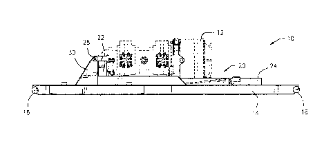
Referring to the drawings in detail, Figure 1 illustrates a side view and
Figure 2 illustrates a
top view of a storage, transport and lift skid assembly 10 with a blowout
preventer 12 (shown in
dashed lines) installed thereon. The present invention will work with a
variety of types and sizes
of blowout preventers, although the blowout preventer does not form a part of
the invention.
The blowout preventer 12 is retained in and secured to the assembly 10 and is
shown in a
horizontal storage and transport position in Figures 1 and 2. The assembly 10
includes a base
frame 14. The base frame 14 may be in the form of a skid with a pair of
opposed tail pipes 16 so
that it may be receivable on a tractor trailer (not shown). The base frame 14
may be lifted or
dragged and off a tractor trailer.
A mounting frame 20 receives the blowout preventer 12 therein. The mounting
frame 20
is movable between a storage and transport position shown in Figures 1 and 2
substantially parallel
to the base frame 14 and an installation position substantially perpendicular
to the base frame 14.
The mounting frame 20 includes a base portion 22 and a back portion 24
substantially
perpendicular thereto. The back portion 24 may include a pair of I-beams
parallel to each other.
6
CA 02893644 2015-06-01
At least one pivot pin permits rotation of the mounting frame 20 with respect
to the base
frame 14. In the present preferred embodiment, a pair of pivot pins 28 pass
through the base
portion 22 of the mounting frame 20 and through a pair of upstanding legs 30
extending upwardly
from the base frame 14. The pivot pins 28 are aligned and, thus, form an axis
of rotation for the
mounting frame 20 as it moves between the horizontal storage and
transportation position shown
in Figures 1 and 2 and the vertical installation position.
Figure 3 illustrates a side view of the assembly 10 partway between the
horizontal storage
and transportation position shown in Figures 1 and 2 and the vertical
installation position.
An actuator mechanism moves the mounting frame 20 between the storage and
transport
position and the installation position. In the present preferred embodiment, a
pair of hydraulic
cylinders 32, each including an extending and retracting ram, are each
pivotally connected at one
end to the base frame 14 and pivotally connected at the opposed end to the
back portion 24 of the
mounting frame 20. As the rams extend, the mounting frame 20 is moved toward
the vertical
installation position. Conversely, as the rams retract, the mounting frame 20
is moved toward the
horizontal storage and installation position.
A plurality of flange locks 34 are attached to the base portion 22 of the
mounting frame 20.
The flange locks 34 are spaced in an annular pattern around the base portion
22. Figure 13
illustrates an enlarged portion of Figure 4 showing a pair of the flange locks
34. Each flange lock
34 includes a pair of opposed plates spaced from each other and a flange
finger therebetween.
The flange fingers are pinned in place to retain the blowout preventer 12 to
the base portion 22 of
the mounting frame. The flange fingers are capable of engaging an annular base
of the blowout
preventer 12 to secure it into position.
7
CA 02893644 2015-06-01
Figures 14 and 15 illustrate two alternate flange fingers 36 and 38 apart from
the flange
locks 34. Depending on the particular blowout preventer 12 to be stored,
transported and
delivered, different sized flange fingers may be utilized. Accordingly, the
assembly of the present
invention may be adapted to various sizes and types of blowout preventers.
Figure 4 illustrates a side view of the assembly 10 shown in the vertical
installation
position. The pair of hydraulic cylinders 32 are actuated to move the blowout
preventer from the
horizontal position. Although hydraulic cylinders are utilized in the present
embodiment, it will
= be appreciated that pneumatic cylinders or another mechanism may be
employed within the spirit
and scope of the invention.
io Once the hydraulic cylinders 32 have moved the mounting frame 20 to
the vertical
installation position, a pair of connecting links 40 pivotally connected to
the base portion 22 of the
mounting frame 20 will be rotated into position and then pinned to the base
frame 14 to lock the
mounting frame 20 into a vertical position. The connecting links 40 are shown
locked in place in
Figure 4.
is The assembly 10 also includes an adjustable blowout preventer cradle
50 which is
adjustably connected to the back portion 24 of the mounting frame 20. The
adjustable cradle 50
may be secured to the back portion by a pair of adjustable brackets 48.
Depending on the height
of the blowout preventer 12, the attachment of the brackets 48 to the back
portion of the mounting
frame 20 may be varied.
20 Figure 6 illustrates the adjustable cradle 50 shown surrounding a
blowout preventer 12
(shown in dashed lines) apart from the assembly 10. The cradle 50 surrounds
the circumference
of the blowout preventer 12.
8
CA 02893644 2015-06-01
Figures 7, 8 and 9 show alternate views of the adjustable cradle 50. Figures 7
and 8 show
the cradle 50 apart from the blowout preventer.
Figure 10 is an enlarged view of a portion taken from Figure 4 showing the
adjustable
brackets 48 which secure the cradle 50 to the back portion of the mounting
frame 20.
Figures 11 and 12 show alternate, exploded views of the adjustable bracket 48
apart from
the cradle 50. The bracket 48 includes a pair of parallel ears having aligned
holes therethrough to
receive a pin 44 to retain the bracket 48 to the cradle 50.
Returning to a consideration of Figures 7, 8 and 9, the cradle 50 also
includes a pair of
opposed projecting ears 52. Each of the ears 52 includes an opening
therethrough.
Figure 5 illustrates a side view of the assembly 10 in the vertical position
adjacent a drilling
or rig floor 54 (a portion of which is shown) having a trolley 56 and a pair
of cables 58. A shackle
with a pin or other connecting mechanism will connect to each ear 52 on the
cradle. The shackle,
in turn, may be connected to cables or wire lines.
Once the blowout preventer is in a vertical position, it may be moved off the
assembly.
The flange locks 34 are detached from the base of the blowout preventer 12.
The cradle 50 can be
detached from the back portion of the mounting frame 20. A lift mechanism may
be utilized to
lift the blowout preventer 12 from the assembly 10 and move it in place over a
well center line (not
shown).
The cradle 50 includes a gate 60 which may be unpinned from the adjustable
cradle 50 and
removed for insertion and removal of the blowout preventer 12. In the event
that a blowout
preventer with a smaller diameter is utilized, an optional filler (not shown)
may be inserted.
Figure 9 illustrates the gate 60 pinned to the cradle 50 with the gate 60 also
shown in
dashed lines exploded therefrom.
9
CA 02893644 2015-06-01
In certain applications, the cradle 50 may remain installed on the blowout
preventer 12
during operation with the well. In other applications, the cradle will be
removed during operation
with the well.
The present invention provides an efficient mechanism to store and transport a
blowout
s preventer as well as move the blowout preventer for installation at the well
site. A single
assembly will accommodate multiple types and sizes of blowout preventers.
Whereas, the present invention has been described in relation to the drawings
attached
hereto, it should be understood that other and further modifications, apart
from those shown or
suggested herein, may be made within the spirit and scope of this invention.